, Gila Perk2, Natesa G. Pandian3, Hans-Joachim Nesser4 and Itzhak Kronzon2
(1)
Department of Cardiology, Cardiocentro Ticino, Lugano, Switzerland
(2)
Non-Invasive Cardiology, Lenox Hill Hospital, New York, NY, USA
(3)
Tufts University School of Medicine, Boston, MA, USA
(4)
Department of Medicine Elisabethinen, Teaching Hospital, Linz, Austria
Abstract
Real-time three-dimensional transesophageal echocardiography (RT 3D TEE) appeared in the clinical arena a few years ago and was welcomed by cardiologists involved in echocardiography as one of the major advances in the twenty-first century. RT 3D TEE is now a well-established technique, able to provide anatomic details of the internal structure of the heart in a living patient. The purpose of this chapter is to describe some basic technical aspects and, more importantly, tell how to acquire 3D images.
Real-time three-dimensional transesophageal echocardiography (RT 3D TEE) appeared in the clinical arena a few years ago and was welcomed by cardiologists involved in echocardiography as one of the major advances in the twenty-first century. RT 3D TEE is now a well-established technique, able to provide anatomic details of the internal structure of the heart in a living patient. The purpose of this chapter is to describe some basic technical aspects and, more importantly, explain how to acquire 3D images. Currently, only two companies provide clinically available RT 3D TEE instrumentation with matrix array transducers. Nonetheless, basic principles described below may be considered general and potentially applicable to other 3D TEE matrix array transducers that will be available from other vendors. However, readers must be aware that some steps regarding data acquisition and processing may be unique to our system (i.e., Philips Medical Systems; Andover, Massachusetts, USA) and not applicable to others.
1.1 Brief Overview of the Technology
1.1.1 A New Generation of Piezoelectric Crystals
“Piezoelectric effect” (the Greek word πιέζειν means pressure) describes the relation between mechanical deformation and electrical voltage. A piezoelectric crystal increases and decreases its thickness when appropriately placed in an alternating electrical field. The mechanical deformation depends on the disposition of highly polarized molecules (dipole) in the crystal. In a monocrystal, the polar axis of all the dipoles (i.e., the imaginary line that passes through the center of the dipole) lies in one direction. This crystal is said to be symmetric. In a polycrystalline compound, different regions within the material have different polar axes. This material is said to be asymmetric. Under a strong electrical field, the molecules of these compounds tend to be oriented in a more homogenous pattern (i.e., the long axis of the molecules becomes oriented towards the surface of the crystal). This phenomenon is called “polarization.” By aligning dipoles more perpendicular to the surface of the crystal, polarization causes the material to expand. A rapid on-off electrical field produces rapid changes in thickness. These mechanical vibrations generate compressions and rarefactions of the same frequency in the surrounding medium; in other words, they generate sound waves.
If the entire electrical energy is converted into mechanical energy, the so-called electromechanical coupling efficiency would be 100 %. The electromechanical coupling efficiency is of paramount relevance for image quality.
Important groups of polycrystalline compounds used for many years in ultrasound machines are ceramics called PZT/polymer (lead-zirconate-titanate composites). Natural impurities within the polycrystalline structure and boundaries between different regions of the PZT/polymer material prevent a perfect alignment of dipoles. Thus only a fraction of dipoles can be aligned by an electrical field and contribute to the acoustic response of the material, making the electromechanical coupling efficiency of these composites less than optimal.
Conversely, a new generation of piezoelectric crystals (PureWave crystals) has a much more uniform atomic arrangement and exhibits fewer defects, with fewer impurities and boundaries. When the crystals are under an electrical field, a near-perfect alignment of dipoles can be obtained, resulting in a dramatic enhancement of electromechanical properties. The ability of these crystals to change thickness under an electrical field (strain) is ten times greater than that exhibited by traditional crystals (Fig. 1.1). In other words, compared with the traditional PZT/polymer composites, these new crystals can convert electrical energy into mechanical energy and vice versa with greater efficiency.
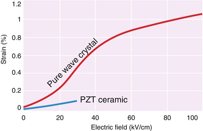
Fig. 1.1
Strain behavior of PureWave crystals versus traditional PZT-type material (Courtesy of Philips Medical Systems; Andover, Massachusetts, USA)
Moreover, the crystals have a larger bandwidth: when vibrating, they generate a spectrum of frequencies with a range twice that of the traditional PZT/polymer composites. The result is better flexibility between resolution (higher frequencies) and penetration (lower frequencies). The wider range of frequencies also allows greater sensitivity in transmitting and receiving multiple second harmonic frequencies, thus improving penetration and border delineation (Fig. 1.2).
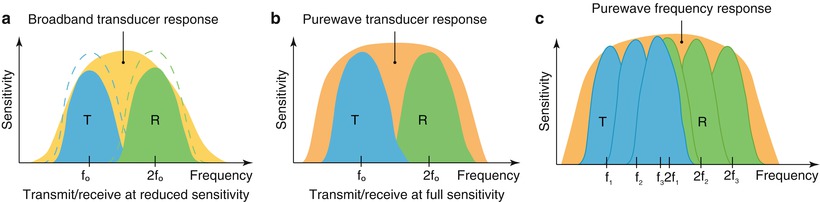
Fig. 1.2
Comparison of conventional harmonic imaging (a), PureWave transducer sensitivity/bandwidth (b), and multiple-pair, second harmonics (c) for different types of applications (Courtesy of Philips Medical Systems)
In conclusion, Purewave crystal perfect arrangement of atoms and superior strain capabilities, in conjunction with higher bandwidth, offer significant performance advantages, particularly in penetration and imaging resolution.
1.1.2 The Matrix Array Transducer
Instead of having a single column of 128 linear elements, as in traditional transducers, the revolutionary idea forming the basis of 3D TEE was to use a matrix array comprising at least 2,500 square crystals in more than 50 rows and 50 columns (the “matrix array transducer”).
In the conventional 2D transducer, the 128 linear elements are activated by applying time delays between each element; i.e., they are activated slightly “out of phase.” The wave fronts from each element sum up, creating a single ultrasound wave, which propagates into the medium at an angle to the surface of the transducer determined by the delay in time between successive elements. A rapid change in delays causes a change in the beam direction. A to-and-fro sweeping action of a scan line enables the production of a sector up to 90° in the lateral direction, up to approximately 16 cm in the axial direction, and negligible thickness in the elevation axis.
In the matrix array transducer, the beams are simultaneously steering in two orthogonal directions (azimuthal and elevation), acquiring a series of 2D sectors along the elevation axis to create a 3D pyramidal dataset. One result of this arrangement is simultaneous imaging of two orthogonal planes of the same structure in real-time, without resolution degradation. The strength of this system is the direct acquisition of a pyramidal volume of echo data, creating a new imaging modality: real-time 3D imaging.
1.1.3 “Live” Imaging
Three-dimensional TEE enables the generation of real-time, “live” 3D echocardiographic moving images as they occur. Notably, the emerging field of 3D interventional echocardiography (to which this Atlas is dedicated) depends exclusively on the instantaneous generation of 3D imaging.
To produce real-time four-dimensional images (i.e., three spatial dimensions plus motion), volume datasets must be acquired and displayed faster than the capacity of the human eye to retain a visual impression, which is estimated as one tenth to one thirtieth of a second. In other words, a 3D volume dataset is obtained (by acquiring a series of 2D planes) and is displayed with a negligible delay, so that the 3D images are updated as quickly as the observer’s visual perception. To overcome the technical bottleneck of fixed ultrasound wave speed, a new microelectronic pulse transmitting-receiving technique was developed, which is based on parallelism or multiline acquisition: in an effort to speed imaging, the system transmits one wide beam and receives multiple narrow beams in parallel. In this way the frame rate can be increased by a factor equal to the number of receiving beams. Unfortunately, increasing the number of receiving beams requires a corresponding increase in the width of the transmitted beam, which leads to a worse signal/noise ratio and worse resolution. A good compromise between speed and image quality in multiline acquisition seems to be a ratio of 16:1 (i.e., 16 lines analyzed per each transmitted beam).
1.1.4 The Advantages of a Transesophageal Approach
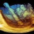
The miniaturization of integrated circuits allows 2,500 crystals to fit into the tip of the transesophageal transducer, resulting in an unprecedented 3D perspective of the heart valves with TEE because the transesophageal approach is not limited by the chest wall and lungs. The thoracic wall is formed by different tissue layers with varying degrees of adipose, connective, and muscular tissues. Because of their different acoustic impedance, in transthoracic echocardiography (TTE) these tissues may distort the traveling ultrasound beam from its path, and returning echoes may contain annoying signals (aberrations or multipath reflections) that may degrade the image. Conversely, because the wall of the esophagus is mainly a thin layer of muscular tissue covered by squamous epithelium, the distortion of ultrasound waves is minimized, and these aberrations are reduced in TEE. Moreover, the esophagus is very close to the heart (Fig. 1.3


Related posts:


Stay updated, free articles. Join our Telegram channel
Full access? Get Clinical Tree
