
The Mechanical Arm System
Orientation is one of the most important factors in successful intracranial surgery. Surgical plans are based mainly upon images generated by computed tomography (CT) or magnetic resonance imaging (MRI). They are sometimes based on functional images such as functional MRI (fMRI), magnetoencephalographs (MEGs), and near infrared spectroscopic topography (NIRS) that are obtained as part of preoperative examinations, especially when patients have lesions in the vicinity of eloquent areas. In such cases, the surgery is planned intimately upon those images in determining the resection line to protect eloquent areas such as the motor strip, language area, or visual cortex.
However, transferring the surgical plan to the real operating field presents a dilemma—one that the surgical navigation system was developed to resolve. The first navigation system was reported by Roberts in 1985.1 He used an ultrasonic three-dimensional (3-D) localizing system to detect the visual field of a microscope.2 In 1986, a navigating system using a mechanical arm and dubbed “neuronavigator” was reported by Watanabe et al.3 Figure 5–1 shows a recent model of our neuronavigator linked to a laptop computer.
Prior to the appearance of navigation systems, the stereotactic surgical frame was used to guide the needle into the brain. In 1947 Spiegel and Wycis4 developed the first stereotactic frame. The needle control was based upon a pneumogram that delineated only the shape of the ventricles. Everything was located in relation to the anterior commissure and posterior commissure that were identified by the pneumoventriculograph. After the development of CT and MRI, stereotaxy had been guided by digital images. By means of these tomographic images, the targeting method has become more direct and more accurate. However, the frame itself became a hindrance for surgical procedures in opencranium surgery. Consequently, the need arose for a frameless navigation system.
 Method
As already mentioned, in 1987 Watanabe et al described their “neuronavigator,” an arm-based, frameless guiding system (so named for its similarity to a car-navigating system designed at that time).3 Several mechanical arm systems based on similar concepts were subsequently developed.5–7
The system works in general as follows. A mechanical arm system samples 3-D coordinates of the operating point and transfers them to a personal computer. The arm has six joints that allow the tip to be introduced into the surgical field. Each joint has a potentiometer that conveys the angle of the joint to the computer. The computer, running on Windows 98, calculates the 3-D location of the arm tip using these angles and arm length with trigonometry.
Preoperative CT or MRI images were acquired with three markers placed on the nasion and bilateral ear tragi. Capsules (about 4 mm in diameter) containing oily materials such as vitamin D are used as markers for MRI, and metallic balls (3 mm in diameter) are used for CT. These images are transferred to the computer via Ethernet. After the patient’s head is fixed to the skull clamp, the arm tip points to the three fiducial points to register the 3-D location of these points on the computer. The computer then creates a conversion matrix with which points in the surgical field are transferred onto the CT/MRI coordinates.
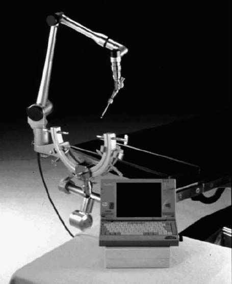
FIGURE 5–1. Basic construction of the neuronavigator, using a laptop PC running Microsoft Windows.
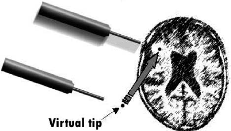
FIGURE 5–2. Designing of a craniotomy by the neuronavigator using a virtual tip. The craniotomy is easily designed in terms of proper size and placement using this method.
We usually use series of two-dimensional (2-D) slice images in three coordinates (axial, coronal, and sagittal). These triplanar images may be displayed in paging mode or fixed mode. Crosshair cursors are displayed on the corresponding images indicating the position of the arm tip.
 Applications in Neurosurgery
The navigator is most often used to detect the localization of tumors. It is especially helpful when the tumor is located deep in the brain. To guide the surgeon to the target, the navigator tip is introduced from time to time into the operating field to check the orientation during the approach.
Virtual tip
Sometimes, it may be helpful when the system indicates the location of the point some distance ahead to the actual tip. For example, when we are dissecting the white matter toward the tumor, it is more informative when the navigator indicates the location of the point before we reach it, which allows us to know the existence of the cistern of large vessels before we encounter them. To achieve this function the navigator system is equipped with a virtual tip that indicates a point located at a desired distance ahead of the actual tip (Fig. 5–2). This is realized by simply retracting the arm tip by the desired length or by telling the computer to elongate the last segment in the software.8–10
The virtual tip is helpful in several situations. As just described, the virtual tip allows the surgeon to know the location of important structures such as large vessels before the surgeon actually encounters these structures. For this purpose the virtual tip is usually located 5 to 10 mm ahead of the actual tip. In cases where the tumor is located on the surface of the brain, as in convexity meningioma, the virtual tip helps to locate the tumor from the scalp surface before the skin incision is made. In this way, the craniotomy is easily designed in terms of desirable size and location. For this purpose, the virtual tip is usually placed at 20 to 30 mm ahead of the actual tip.
Combination with magnetoencephalographs
Related posts:

Stay updated, free articles. Join our Telegram channel

Full access? Get Clinical Tree


