The Optical Digitizer
Image-guided neurosurgery stemmed from the need to maintain the advantages while overcoming the limitations of frame-based stereotaxy neurosurgery. Accuracy, the main benefit of a stereotactic system, is obtained by employing a rigid coordinate frame that provides a stable frame of reference and an aiming arc assembly that is mechanically stable as it holds the probe in position along a trajectory. Unfortunately, these components also produce the greatest limitations in the surgical space. Thus, several investigators have pursued novel technologies of interactive image-guided neurosurgery to provide accurate intraoperative cranial navigation without being constrained by the design limitations inherent to stereotactic frame systems.
Interactive image-guided neurosurgical systems include four fundamental components: a method for registration of image space to physical space, an interactive localization device, a computer and interface, and methods of real-time intraoperative feedback. Interactive localization devices include: mechanical arms, digitizers (sonic, optical, magnetic), machine-video devices, real-time ultrasonography, and intraoperative magnetic resonance and computed tomography (MR-CT).
Bucholz and colleagues first introduced the use of the optical digitizer for intracranial navigation in 1993.1,2 Since its introduction, this interactive localization device has proved very helpful in image-guided neurosurgery. Consequently, it became an integral component of several currently marketed image-guided systems.3–9 The senior author has been using the optical digitizer in her clinical practice since August 1993.3,4 This chapter provides a brief technical overview of the optical digitizer and other components needed for neurosurgical navigation, and reviews the basic steps of the optical digitizer’s clinical use for intracranial procedures.
 Technical Overview
Navigation systems utilizing the optical digitizer include the following components: (1) the digitizer; (2) a light detector array or “cameras;” (3) a reference frame hosting “fixed” light-emitting diodes (LEDs), (4) surgical instruments with LEDs that can be tracked by the digitizer, and (5) a computer workstation and software to reformat and display preoperative images and to render intraoperative localization of the surgical instrument(s) overlapped to the preoperative images (Fig. 4–1). Additionally, some systems have a real-time intraoperative updating of the images using ultrasound or magnetic resonance imaging (MRI).10
Optical digitizer
The critical component of an image-guided system is the three-dimensional (3-D) digitizer, which determines position. The accuracy of the intraoperative localization will be limited by that of the digitizer used. Digitizers are computerized systems that provide coordinate addresses for any accessible point within their working volumes. They can be classified into two broad groups: linked and nonlinked. Linked digitizers require a mechanical link between the digitizer and the pointer used intraoperatively to confirm localization.11 This type of digitizer is typically a mechanical arm and relies upon angle detectors located in joints within the arm to determine the position. By determining the angle of each joint, the position of the tip of the device can be determined with reference to its base. The base is connected with the patient’s head, and the tip is registered to the preoperative images. Thus, by moving the tip of the arm one can determine its location relative to the preoperative images. The nonlinked digitizers, rather than relying on the link just described, rely upon the detection of signals generated by emitters or receptor arrays. A variety of digitizing technologies are currently available, including optical, sonic, and magnetic digitizers.1,11–13 Most optical digitizers are based on multiple cameras fitted with linear-charged coupled devices and cylindrical lenses that detect LEDs or reflective devices within the surgical field.
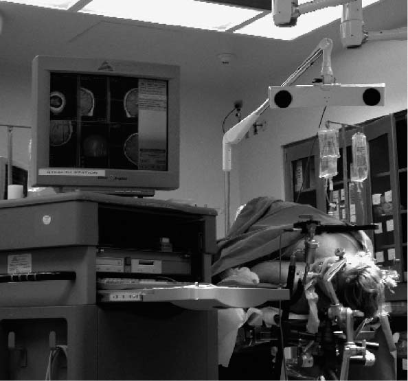
FIGURE 4–1. The computer workstation, optical digitizer, camera array, and reference arc demonstrating the intraoperative setup (StealthStation, Louisville, CO).
Light detector array
The optical digitizer uses a camera array to detect the position of infrared light emitted by LEDs. These camera arrays are mounted on the reference frame and on the surgical instruments (see the section, Surgical instruments). Usually the detector array is placed 3 to 4 feet over the patient’s lower extremities. There is a “sweet” location spot for the detection array, and this is displayed on the computer screen while the array is being positioned (see the section, Positioning and Registration).
Reference frame
The reference frame hosts a fixed set of LEDs, typically four or five, and is usually mounted to maintain a fixed relationship to the skull or spine throughout the surgery. This can be accomplished by mounting the reference frame to the head holder for cranial procedures, directly to the skull for skull base procedures, or to the spinous process for spinal cases.
Surgical instruments
Almost any instrument can be equipped with LEDs. Because the coagulation forceps are the most frequently used in microsurgery, the authors usually prefer to use this instrument for cranial navigation. For most instruments, a linear array of LEDs, typically three, is sufficient to obtain accurate localization of the instrument in space. For other instruments with a more complex 3-D shape, the LEDs, typically four, are mounted on a butterfly-shaped structure to provide for redundancy and allow for calibration of the instrument tip.
Computer workstation and software
Computer workstations use commercially available hardware. Examples include the StealthStation using a UNIX-based work station (Indigo graphics workstation, Silicon Graphics, Mountain View, CA) and the Cbyon suite (Cbyon, Palo Alto, CA) utilizing a dual processor PC running Windows 2000 software and its proprietary graphic engine.
Images can be displayed using a variety of reconstructed images. The three standard views, axial, sagittal, and coronal, with a 3-D reconstruction are often used for preliminary planning. Orthogonal views obtained in the trajectory of the probe are particularly helpful in planning a biopsy (Fig. 4–2).14 The “probe view” is an interactive view that allows visualization of the planned path of microsurgical dissection. Additionally, neurophysiological atlases can be overlapped to standard views to facilitate surgical planning for movement disorders (Fig. 4–3).15 Finally, image fusion using different modalities, such as functional MRI (fMRI), CT, positron emission tomography (PET), and others can be used to improve planning for functional cases. The position of the surgical instrument is represented by a crosshair on the above described images. The monitor displaying the images is usually kept to the surgeon’s side. Some surgeons, however, prefer not to move the head from the operating field or microscope. Therefore, these views can be incorporated to a head-mounted display or to the optics of the operating microscope.16,17
 Neuronavigation Procedure
Neuronavigation allows real-time feedback whereby the position of surgical instruments is projected over the preoperatively acquired images. Additionally, intraoperative update of the images can reflect the amount of resection performed. The option to have intraoperative, real-time feedback on the location of the surgical instruments adds the following steps to the neurosurgical procedure: preoperative imaging and data transfer according to established protocols, planning and virtual surgery, and registration (i.e., the process that allows “overlap” between the imaging and physical spaces). Although a learning curve is required to optimize the smoothness of such operations, they eventually become routine and do not interfere significantly with the overall surgical procedure.
Preoperative imaging and data transfer
As just described, image-guided neurosurgery allows the surgeon to obtain intraoperative real-time visualization of the surgical instruments overlapped on the patient’s preoperative images. To accomplish this, preoperative images need to be registered to the patient’s anatomy and must be acquired using a specific protocol.3,4 Two aspects must be taken into account prior to obtaining preoperative images for neuronavigation: protocol for image acquisition and use of fiducials.
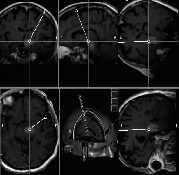
FIGURE 4–2. Intraoperative photo of the computer screen displaying magnetic resonance reformatted images used for surgical planning and intraoperative guidance. Clockwise from the upper left: coronal, sagittal, “trajectory” 1, axial, 3-D, and “trajectory” two. Trajectory views are images reformatted in planes orthogonal to the surgical instrument. These are particularly helpful when planning for a biopsy (StealthStation, Louisville, CO).
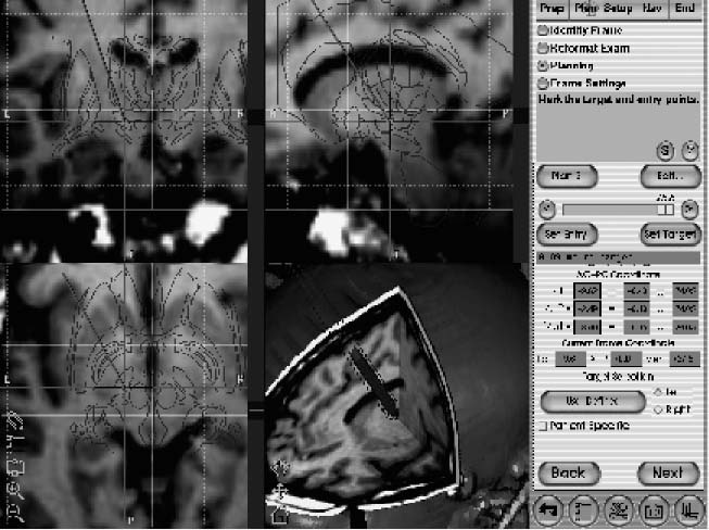
FIGURE 4–3. Intraoperative photo of the computer screen displaying magnetic resonance images. Clockwise from upper left: coronal, sagittal, axial, and 3-D. A patient-fitted Schaltenbrand neurophysiological atlas is displayed overlapped to the triplanar images to further assist the planning and intraoperative guidance of placement of a deep brain electrode in the subthalamic nucleus (StealthStation, Louisville, CO).
Image acquisition
The protocol for image acquisition has a significant impact on the accuracy of the frameless system used. In particular the thickness and field of view of the preoperative images dictate the ultimate accuracy of the neuronavigation. In fact, the accuracy of the information obtained from the navigation system is equal to the thickness of the images plus the error inherent to each system used. Therefore, for a system that claims “one millimeter” accuracy, in the best circumstances this should be added to the 2, 3, or 4 mm thickness of the images used. Thus, when reading or hearing about the publicized “submillimetric accuracy” of frame-based or frameless systems the user should be aware that the claimed accuracy must be added to the thickness of the preoperative images. For this reason, it is advisable to use thin sections for preoperative images. Additionally, when planning the image acquisition scout, the surgeon should make sure that the region of interest is included. Thus, when planning for an entry point on the convexity, this must be part of the scanned field to allow accurate localization of the entry point intraoperatively.
Images are then transferred to the workstation over a local network using a conventional DICOM protocol or employing the archive media present on the scanners used, typically a digital archive tape (DAT) or CD-ROM.
Fiducials or markers
A variety of registration techniques offer alternative methods for mapping images to each other or to the physical space. Point-based registration methods define corresponding points in different images or physical space, determine their spatial coordinates, and calculate a geometric transformation between the volumes. These points, known as fiducials, may be extrinsic and must be applied to the patient prior to obtaining the preoperative images, or intrinsic and based on patient-specific anatomical landmarks. Registration using the patient’s own anatomical landmarks is an appealing concept because it obviates the need to have trained personnel applying the fiducials. This method is currently used mostly for spine surgery. For cranial surgery, however, studies and clinical experience have shown that this process may be less accurate18
Stay updated, free articles. Join our Telegram channel

Full access? Get Clinical Tree


