The Pelvis and Hips
Introduction
This chapter will address clinical and imaging aspects of orthopaedic procedures in the pelvis and hips. Pelvic fractures, fracture/dislocations of the hip, intertrochanteric and subtrochanteric fractures, and treatment approaches will be reviewed in the first section. Joint replacement procedures will be discussed in the second section. This will include clinical indications, preoperative decisions and imaging, and imaging of joint replacement complications. The final section will review osteotomies of the pelvis and hips and hip arthrodeses.
Trauma
Imaging plays an important role in detection, classification, and evaluation of complications related to fractures of the pelvis and hips and their treatment.
Pelvic Fractures
Pelvic fractures account for only 2% to 3% of all skeletal injuries. Minor fractures occur more commonly in elderly patients. Most significant injuries (double breaks in the pelvic ring) more commonly occur with high-velocity trauma in younger individuals (50% younger than 50 years). Morbidity and mortality rates can be significant with more severe pelvic fractures.
Fracture Classification
Multiple classification systems have been used over the years. Most based the classification on location, mechanism of injury, and stability.
TILE CLASSIFICATION | ||||||||||||||||||||||||
|---|---|---|---|---|---|---|---|---|---|---|---|---|---|---|---|---|---|---|---|---|---|---|---|---|
|
KEY AND CONWELL CLASSIFICATION | |||||||||||||||
|---|---|---|---|---|---|---|---|---|---|---|---|---|---|---|---|
|
YOUNG AND BURGESS CLASSIFICATION—BASED ON RADIOGRAPHIC PATTERNS | ||||||||||||||||||||||||||||||||||||
|---|---|---|---|---|---|---|---|---|---|---|---|---|---|---|---|---|---|---|---|---|---|---|---|---|---|---|---|---|---|---|---|---|---|---|---|---|
| ||||||||||||||||||||||||||||||||||||
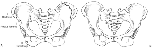 Fig. 4-1 Illustrations of stable pelvic fractures (Tile type A1, Key and Conwell class I). A: Avulsion fractures of the anterior superior iliac spine (1), anterior inferior iliac spine (2), ischial tuberosity (3), and isolated iliac wing (Duverney fracture) fracture. B: Illustration of isolated transverse sacral fracture (5) and isolated pubic rami fractures (6 and 7). |
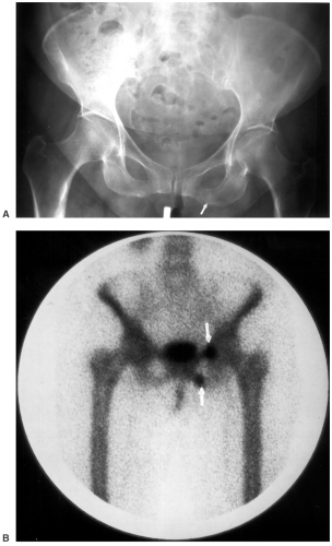 Fig. 4-2 Stable isolated pelvic ring fracture (Tile type A2, Key and Conwell class II). A: Anteroposterior (AP) radiograph demonstrates a subtle fracture (arrow) of the left inferior pubic ramus. B: Technetium 99m methylene diphosphonate (MDP) scan demonstrates undisplaced fractures (arrows) of both pubic rami. |
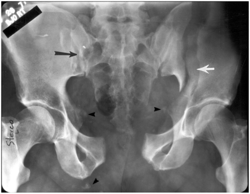 Fig. 4-3 Open book fracture (Tile type B1, Key and Conwell class III, Young and Burgess anteroposterior [AP] compression type III). AP radiograph demonstrating wide diastasis of the pubic symphysis with widening of the right sacroiliac joint (black arrow) and a displaced left ilium fracture (white arrow). There are multiple avulsion fractures (black arrowheads). |
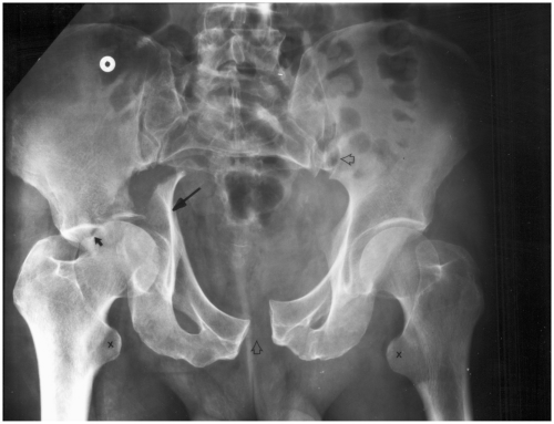 Fig. 4-4 Double break in the pelvic ring with associated acetabular fracture (Tile type C3, Key and Conwell class IV, Young and Burgess combination injury). Anteroposterior (AP) radiograph of the pelvis demonstrates diastasis of the pubic symphysis and left sacroiliac joint (open arrows) with a step off indicating vertical shearing in addition to a displaced acetabular fracture (arrows) due to associated lateral compression. |
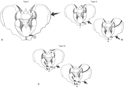 Fig. 4-5 Young and Burgess lateral compression injuries (41% to 72% of pelvic fractures). A: Type I—force applied to the posterior ilium resulting in a crush injury to the ilium, sacrum or sacroiliac joint (1), and oblique or horizontal pubic rami fracture (2). B: Type II—force is applied more anteriorly resulting in fracture or sacroiliac joint diastasis (1), horizontal pubic rami fracture (2), and posterior ligament injury (3) in type IIA or iliac wing fracture with the other associated injuries in type IIB. C: Type III—anterolateral force is applied resulting in diastasis of the contralateral sacroiliac joint (1), oblique or horizontal pubic rami fracture (2), disruption of both sacroiliac and associated posterior ligaments (1, 3, and 4) in type IIIA or with associated iliac wing fracture in type IIIB. |
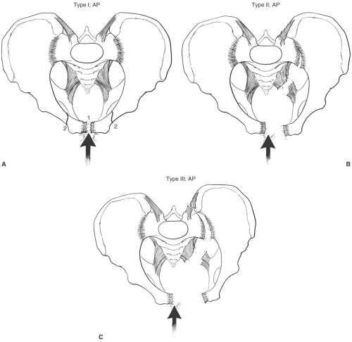 Fig. 4-6 Young and Burgess anteroposterior (AP) compression injuries (15% to 25% of pelvic fractures). A: Type I—force directed anteriorly (large arrow) with minimal diastasis of the pubic symphysis (1) or vertical pubic rami fractures (2). B: Type II—force directed anteriorly (large arrow) with wider diastasis of the pubic symphysis or more displaced vertical pubic rami fractures. C: Type III—force directed anteriorly (large arrow) resulting in wide diastasis of the pubic symphysis or displaced vertically oriented pubic rami fracture and disruption of the sacroiliac ligaments (see Fig. 4-3). |
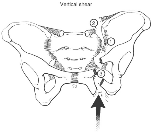 Fig. 4-7 Vertical shearing injuries (6% of pelvic fractures). Force directed vertically resulting in unilateral or contralateral disruption of the sacroiliac joint (1) and ligaments (2) and vertical displaced pubic rami fracture (3). |
Suggested Reading
Key JA, Conwell HE. Management of fractures, dislocations and sprains. St. Louis: Mosby; 1951.
Tile M. Pelvic ring fractures. J Bone Joint Surg. 1988;70B:1–12.
Young JWR, Burgess AR. Radiologic management of pelvic ring fractures. Baltimore: Urban & Schwarzenberg; 1987.
Imaging of Pelvic Fractures
In high-risk trauma patients, an anteroposterior (AP) radiograph of the pelvis is obtained usually followed by computed tomography (CT). However, additional radiographic views and procedures may be required depending on clinical findings and hemodynamic status of the patient.
Radiographs
AP view of the pelvis and hips—detect most anterior fractures, may miss up to 50% of posterior fractures (Fig. 4-3)
Inlet and outlet views—tube is angled 40 degrees to the feet (inlet view) and 40 degrees to the head for females and 25 degrees for males (outlet view); improves detection and position of fracture fragments anteriorly and posteriorly
Additional radiographs, especially of the lower extremity, may be required as 65% of patients have associated fractures beyond the pelvis
Computed tomography: Thin sections with reformatting and three-dimensional (3-D) reconstructions as necessary; intravenous contrast may be useful but can obscure hemorrhage if angiography is required to detect and treat bleeding vessels (see Fig. 4-8).
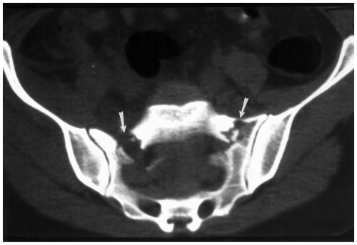
Fig. 4-8 Axial computed tomographic (CT) image demonstrating bilateral sacral fractures (arrows) not clearly demonstrated on radiographs.
Urethrograms: Performed by placing a catheter carefully under fluoroscopic guidance while gently injecting contrast medium in patients with suspected urethral or bladder rupture
Angiography: Identify bleeding vessels; embolization as required
Suggested Reading
Burgess AR, Eastridge BJ, Young JW, et al. Pelvic ring disruptions: Effective classification protocols. J Trauma. 1990;30:848–856.
Resnick CS, Stackhouse DJ, Shanmuganathan K, et al. Diagnosis of pelvic fracture trauma: Efficacy of plain radiographs. AJR Am J Roentgenol. 1992;158:109–112.
Young JW. Pelvic injuries. Semin Musculoskelet Radiol. 1998;2:83–104.
Treatment Options
Treatment options vary with the severity of the injury, presence of distant injuries, and the hemodynamic status of the patient. Minor fractures (avulsion fractures, fractures not involving the pelvic ring) may be treated conservatively (Fig. 4-1). These injuries are rarely associated with significant complications. More complex injuries are approached more aggressively and vary with the patient status. Significant pelvic hemorrhage (71% of patients have significant blood loss) is a common problem and must be addressed immediately. Blood loss and associated injuries create a high morbidity and significant mortality. The overall mortality rate varies from 6% to 22% with 39% of deaths related to uncontrolled hemorrhage. Hemorrhage may be controlled with pressure garments, angiography and embolization, external fixation, or open surgical procedures. This discussion will focus on orthopaedic options. Stability of the injury is critical in planning management. A stable lesion is one that will not undergo further deformity under normal physiologic forces. Examples would include Tile type A and Key and Conwell class I and II fractures. Tile type B fractures are vertically stable, but rotationally unstable. Tile type C fractures are vertically, posteriorly, and rotationally unstable.
External Fixation
External fixation should be considered early in patients with unstable fractures, especially if the patient is hypotensive. Anterior fixation and stabilization can be achieved with external fixation (see Fig. 4-9). However, it is not unusual to require additional posterior internal fixation at a later date to stabilize the posterior complex and sacroiliac joints. When possible, fixation frames should not be placed so as to reduce access for emergency surgical laparotomy.
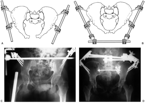 Fig. 4-9 External fixation. Illustrations of Hex-Fix external fixation with Steinman pins and rods attached anteriorly (A) and compression rod linkage (B) for anterior stability. (Courtesy of Smith and Nephew Richards, Memphis, TN.) C: Radiograph demonstrating a vertical shear injury with step off of the pubic symphysis and anterior external fixator in place. D: Radiograph demonstrating anterior external fixation with internal fixation of both sacroiliac joints. Posterior stabilization could not be accomplished with anterior external fixation alone. |
Indications for external fixation
Decrease pelvic volume for hemorrhage control
Fracture reduction and stabilization
Other injuries that prevent internal fixation
Internal Fixation
Conservative treatment with slings and external fixation may be suitable in the acute setting while patients are being stabilized. However, these methods may not be sufficient for treatment of unstable injuries.
Indications for internal fixation
Posterior sacroiliac disruptions (Fig. 4-9D)
Failed closed reduction
Residual deformity after external fixation
Acetabular fractures
Certain open wounds
Vertically unstable fractures
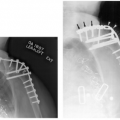
Surgical intervention can be performed in the first several days in patients with stable injuries. Patients with instability and hypotension may require more immediate intervention. Posterior stabilization can be accomplished with threaded rods and bolts with washers (Fig. 4-9D). Plate and screw fixation may also be employed. Anterior stabilization can be achieved with external or internal fixation. Diastasis of the symphysis >2 cm can be stabilized with plate and screw fixation (see Fig. 4-10). When vertical shearing injury has occurred, multiple plates are required to achieve stable fixation (Fig. 4-10C). Acetabular fractures will be discussed in the next section.
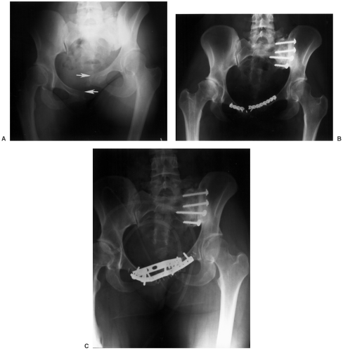 Fig. 4-10 A: Unstable vertical shearing injury with step off of the pubic symphysis (arrows) and left sacroiliac joint. B: Internal fixation of the left sacroiliac joint was accomplished with cancellous screws and washers and there is reconstruction plate and screw fixation of the symphysis. The anterior plate fractured. Therefore, reoperation with two plates (C) was performed to achieve stability. |
Suggested Reading
Failinger S, McGanity PL. Unstable fractures of the pelvic ring. J Bone Joint Surg. 1992;74A:781–791.
Hill RM, Robinson CM, Keating JF. Fractures of the pelvic rami. Epidemiology and five-year survival. J Bone Joint Surg. 2001;83B:1141–1144.
Matta JM, Saucedo T. Internal fixation of pelvic ring fractures. Clin Orthop. 1989;242:83–97.
Tile M. Pelvic fractures: Operative versus non-operative treatment. Orthop Clin North Am. 1980;11:423–464.
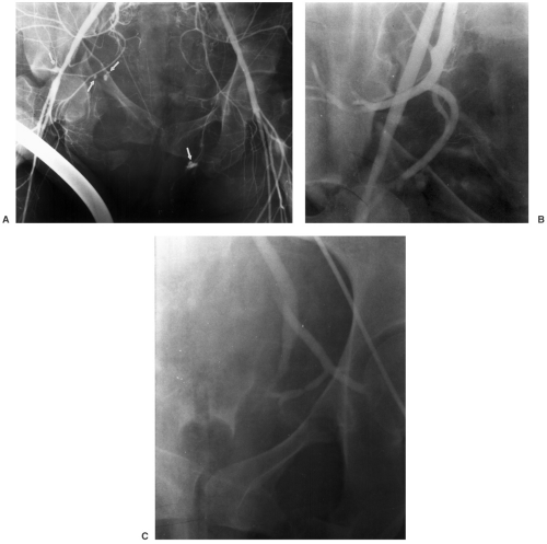 Fig. 4-11 Anteroposterior (AP) compression injury with displaced pubic rami fractures and hemodynamic instability. Angiogram (A) demonstrates bleeding sites bilaterally (arrows). Following embolization the bleeding sites have been occluded (B and C). |
Complications
Complications may be related to the pelvic trauma, associated injuries, or the surgical procedure. The most common and significant complication associated with pelvic fractures is hemorrhage. In the Mayo clinic series, transfusion of up to 10 units of blood was required in 71% of patients with double breaks in the pelvic ring. Mortality rates in this group were 22%. Hemorrhage can be controlled with pressure garments, external fixation systems, angiography with embolization of bleeding vessels, or rarely open surgical intervention (see Fig. 4-11). In recent years, the mortality rate has improved (6% compared to 22% in years past) with 39% of these deaths related to pelvic
hemorrhage. The remaining deaths were related to associated head trauma (31%) or multiorgan failure (30%).
hemorrhage. The remaining deaths were related to associated head trauma (31%) or multiorgan failure (30%).
Genitourinary injuries occur in 19% to 30% of fractures and are most often seen following AP trauma with pubic rami fractures or vertical shearing injuries. Urethral injuries (see Fig. 4-12) are most common (males > females), followed by the bladder (see Figs. 4-13 and 4-14), vagina, and kidney. A carefully performed urethrogram and cystogram is still a useful approach for diagnosis and management (Figs. 4-13 and 4-14). Local neurologic injuries, primarily to the sacral plexus, occur in up to 21% of patients with sacral or sacroiliac joint involvement. Vaginal and rectal injuries occur less frequently. However, the latter may result in an infected hematoma, which results in significant morbidity and increased mortality (∼50%).
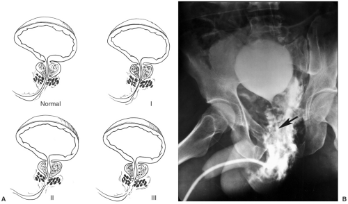 Fig. 4-12 A: Illustration of the normal male urethral anatomy and tears in the urethra. Type I—stretching of the urethra due to pelvic hematoma, type II—urethral tear above the urogenital diaphragm, type III—urethral tear below the urogenital diaphragm. B: Large urethral tear above and below the urogenital diaphragm. Note the catheter position (arrow) which was slowly advanced using fluoroscopic guidance in order to prevent further injury. |
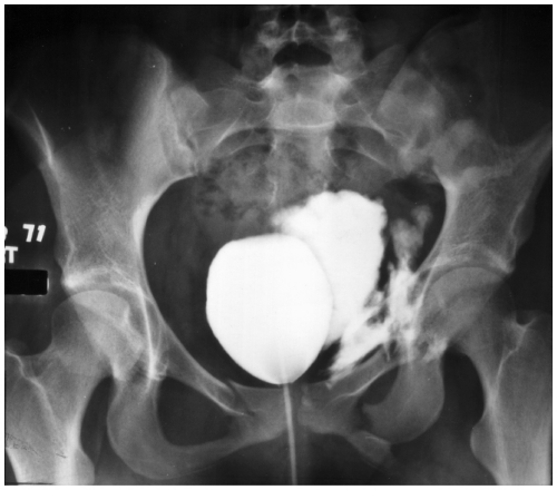 Fig. 4-13 Cystogram demonstrating extravasation of contrast from the bladder due to extraperitoneal rupture following an anteroposterior (AP) compression injury with pubic rami fractures. |
Injuries to the gastrointestinal tract (7%), liver (7%), spleen (10%), and mesentery (4%) also occur. In our series, 11% of patients had associated head, chest, or abdominal injuries. Associated fractures occur in 48% to 65% of patients. Table 4-1 summarizes complications and imaging approaches for complex pelvic fractures.
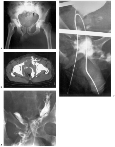 Fig. 4-14 Anteroposterior (AP) compression injury with bladder and urethral injuries. A: AP radiograph demonstrates vertical pubic rami fractures with a subtle posterior sacral fracture (arrow). B: Computed tomography with intravenous contrast demonstrates extravasation of contrast from the bladder and into the pelvis and anterior soft tissues. C: A Foley catheter was placed without fluoroscopic guidance and was improperly placed in the pelvis with contrast extravasation that is obviously not in the bladder. D: Using a guide wire and suprapubic approach the catheter was successfully placed. |
Table 4-1 COMPLICATIONS RELATED TO COMPLEX PELVIC FRACTURES | ||||||||||||||||||||||||||||||||||||||||
|---|---|---|---|---|---|---|---|---|---|---|---|---|---|---|---|---|---|---|---|---|---|---|---|---|---|---|---|---|---|---|---|---|---|---|---|---|---|---|---|---|
| ||||||||||||||||||||||||||||||||||||||||
Suggested Reading
Berquist TH, Lewallen DG, McComb BL. The pelvis and hips. In: Berquist TH, ed. Imaging atlas of orthopaedic appliances and prostheses. New York: Raven Press; 1995:217–352.
Hill RM, Robinson CM, Keating JF. Fractures of the pelvic rami. Epidemiology and five-year survival. J Bone Joint Surg. 2001;83B:1141–1144.
Perez JV, Hughes PMD, Bowers SK. Angiographic embolization in pelvic fracture. Injury 1998;29:191–197.
Acetabular Fractures
Acetabular fractures account for 24% of pelvic injuries. Fractures of the acetabulum may be simple or complex. The latter have complications similar to complex pelvic fractures. The acetabulum is anatomically similar to an inverted “Y” with anterior and posterior columns. The type of fracture is related to the position of the femur or femoral head when the force is applied to these structures and extends into the acetabulum. The position of the femur at the time of injury dictates the type and extent of fracture (see Figs. 4-15 and 4-16).
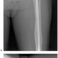
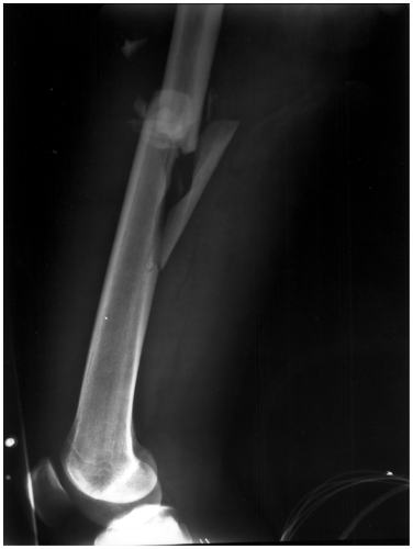 Fig. 4-15 Radiograph of the femur demonstrating a comminuted midshaft fracture in a patient with a complex pelvic fracture. |
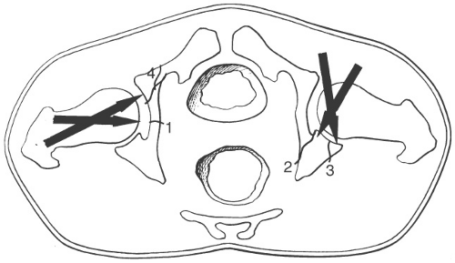 Fig. 4-16 Illustration of force direction of the femur (large arrows) in relation to type and extent of acetabular fractures. 1—central fracture; 2—posterior wall or column; 3—posterior rim; 4—anterior wall. |
Fracture Classification
There are multiple classification systems for acetabular fractures. These include the Tile, Judet and Letournel, AO
(Arbeitsgemeinschaft fur Osteosynthesefragen), ATO (Orthopaedic Trauma Association), and more recently a CT classification system proposed by Harris et al. Classification systems are based on the extent of injury and provide guidance for fracture management. The anatomy of the acetabulum can be accurately depicted on radiographs and CT (see Fig. 4-17). As noted earlier, the acetabulum comprises three osseous structures that form an anterior and posterior column. The anterior column is larger extending inferiorly from the iliac wing to the superior pubic ramus. The posterior column begins at the sciatic notch and extends inferiorly to the ischium. Different fracture patterns are summarized in the classification systems discussed in the subsequent text.
(Arbeitsgemeinschaft fur Osteosynthesefragen), ATO (Orthopaedic Trauma Association), and more recently a CT classification system proposed by Harris et al. Classification systems are based on the extent of injury and provide guidance for fracture management. The anatomy of the acetabulum can be accurately depicted on radiographs and CT (see Fig. 4-17). As noted earlier, the acetabulum comprises three osseous structures that form an anterior and posterior column. The anterior column is larger extending inferiorly from the iliac wing to the superior pubic ramus. The posterior column begins at the sciatic notch and extends inferiorly to the ischium. Different fracture patterns are summarized in the classification systems discussed in the subsequent text.
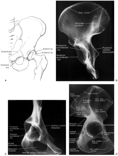 Fig. 4-17 A: Illustration of the anterior and posterior acetabular margins and iliopectineal line (anterior column) and ilioischial line (posterior column). Specimen radiographs in the posterior oblique (posterior Judet view) (B), anterior oblique (anterior Judet view) (C), and sagittal plane (D) demonstrating the acetabular margins and anterior and posterior columns. |
LETOURNEL AND JUDET CLASSIFICATION—TEN BASIC PATTERNS DIVIDED INTO ELEMENTARY AND ASSOCIATED PATTERNS | ||||||||||||
|---|---|---|---|---|---|---|---|---|---|---|---|---|
|
ARBEITSGEMEINSCHAFT FUR OSTEOSYNTHESEFRAGEN CLASSIFICATION SYSTEM | ||||||||||||||||||||||||||||||
|---|---|---|---|---|---|---|---|---|---|---|---|---|---|---|---|---|---|---|---|---|---|---|---|---|---|---|---|---|---|---|
| ||||||||||||||||||||||||||||||
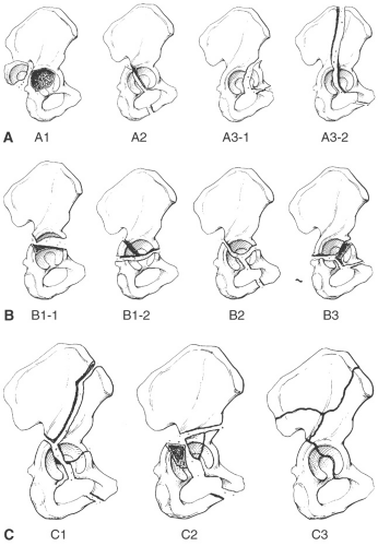 Fig. 4-18 AO (Arbeitsgemeinschaft fur Osteosynthesefragen) fracture pattern classification. A: Type A—A1-posterior wall; A2-posterior column; A3-1-anterior wall; A3-2-anterior column. B: Type B—B1-1-transverse; B1-2-transverse with posterior wall fragment; B2-“T” fracture; B3-anterior column with posterior wall fracture. C: Type C—C1-both columns with fracture extending to iliac crest; C2-anterior column extending to anterior inferior iliac spine; C3-both columns with fracture extending to sacroiliac joint. |
COMPUTED TOMOGRAPHIC CLASSIFICATION SYSTEM: HARRIS, COUPE, LEE, AND TROTSCHER | ||||||||||||||||||
|---|---|---|---|---|---|---|---|---|---|---|---|---|---|---|---|---|---|---|
|
Two-column fractures, transverse fractures with posterior wall involvement, and posterior wall fractures account for 66% of acetabular fractures. T and transverse fractures are the next two most common injuries. These five patterns account for 90% of acetabular fractures (see Fig. 4-19).
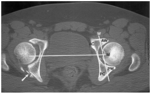 Fig. 4-19 Computed tomographic (CT) classification by Harris, Coupe, Lee, and Trotscher. Axial CT image demonstrating a posterior wall fracture on the left with multiple small fragments (arrow). Vertical line (M) separates the anterior (AC) and posterior (PC) columns. Line (W) through the lunar articulating surface defines and anterior (AW) and posterior (PW) walls. Therefore the fracture on the left would be a posterior wall fracture or type 0. |
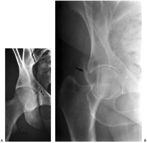 Fig. 4-20 Anterior oblique Judet views demonstrating an undisplaced central acetabular fracture (curved arrow in A) and posterior wall fracture (arrow in B). |
Suggested Reading
Durkee NJ, Jacobson J, Jamadar D, et al. Classification of common acetabular fractures: Radiographic and CT appearances. AJR Am J Roentgenol. 2006;187:915–925.
Harris JH, Coupe KJ, Lee JS, et al. Acetabular fractures revisited: 2. A new CT based classification. AJR Am J Roentgenol. 2004;182:1367–1375.
Letournel E, Judet R. Fractures of the acetabulum, 2nd ed. Hiedelberg, Germany: Springer-Verlag, New York; 1993.
Tile M, Kellam J, Joyce M. Fractures of the acetabulum: Classification, management protocols and results of treatment. J Bone Joint Surg. 1985;67B:324–335.
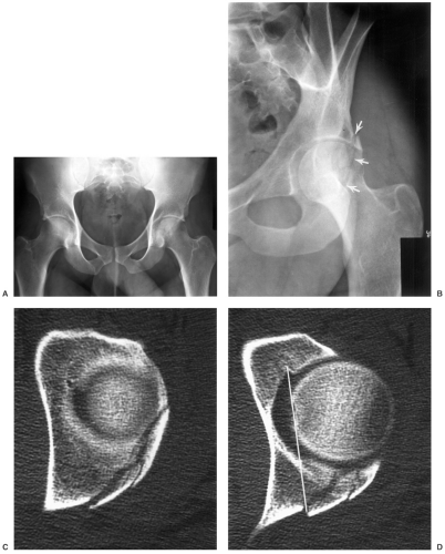 Fig. 4-21 Posterior wall and column fracture. A: Anteroposterior (AP) radiograph of the pelvis does not clearly demonstrate the fracture. B: Anterior Judet view demonstrates a posterior fracture extending along the rim (arrows). Computed tomographic (CT) images (C and D) demonstrate comminution of the posterior wall with extension into the posterior column (line in D). AO type A1-2, Harris type I. E: AP radiograph following internal fixation with reconstruction plate and screws. |
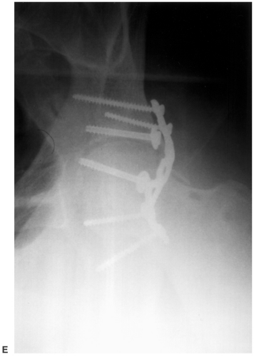 Fig. 4-21 (Continued). |
Imaging of Acetabular Fractures
Imaging of acetabular fractures has traditionally been accomplished with screening radiographs. AP views of the hip along with Judet views (45 degrees anterior and posterior rotation of the involved side) should be obtained (Figs. 4-17 and 4-18). Up to 30% of undisplaced fractures are overlooked without Judet views (see Fig. 4-20). Currently, CT is most commonly obtained following AP radiographs to fully evaluate the extent of involvement (see Fig. 4-21). Coronal and sagittal reformatted images are useful to effectively classify the injury. 3-D reconstructions can also be obtained (see Fig. 4-22).
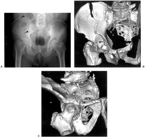 Fig. 4-22 Complex acetabular fracture. A: Anteroposterior (AP) radiograph demonstrates a fracture extending through the right ilium (arrowheads). The femoral head appears medially displaced, but a fracture line is not clearly defined. Oblique three-dimensional (3-D) images (B and C) clearly demonstrate the fracture in the ilium and the involvement of the acetabular dome and anterior column (arrowheads). |
Treatment Options
The goals for treatment of acetabular fractures are to reestablish the articular anatomy and preserve joint function. Treatment is based on fracture pattern, patient status, and associated injuries. Patient age, weight, and activity status must also be considered. Minimally displaced fractures (2 to 5 mm), even if the dome is involved, can be managed conservatively. In some cases, displaced fractures can be treated with external fixation or percutaneous screw placement techniques. These approaches reduce blood loss, infection rates, and neurovascular complications. However, the standard for treatment of displaced fractures is open reduction and internal fixation.
Indications for internal fixation
Unstable posterior fragment (Fig. 4-21)
Displaced acetabular dome fractures (see Fig. 4-23)
High T fractures
Displaced two-column fractures (see Fig. 4-24)
Retained joint fragments
Femoral head or Garden III or IV neck fractures
Results following internal fixation are good to excellent in 80% to 90% of patients. Only approximately 8% of patients require reoperation, usually hip arthroplasty for secondary osteoarthritis.
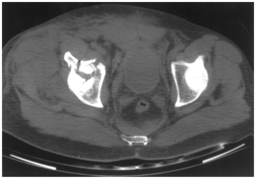 Fig. 4-23 Axial computed tomographic (CT) image demonstrating a displaced acetabular dome fracture. |
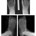
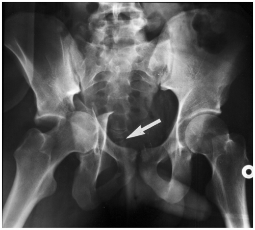 Fig. 4-24 Anteroposterior (AP) radiograph demonstrating a severely displaced two-column fracture (arrow). |
Suggested Reading
Crowl AC, Kahler DM. Closed reduction and percutaneous fixation of anterior column acetabular fractures. Comput Aided Surg. 2002;7:169–178.
Giannoudis PV, Grotz MRW, Papakostidis C, et al. Operative treatment of displaced pelvic fractures of the acetabulum: A META-analysis. J Bone Joint Surg. 2005;87B:2–9.
Judet R, Judet J, Letournel RE. Fractures of the acetabulum: Classification and surgical approaches to open reduction. J Bone Joint Surg. 1964;46A:1615–1647.
Matta J, Merritt PO. Displaced acetabular fractures. Clin Orthop. 1988;230:83–97.
Starr AJ, Reinert CM, Jones AL. Percutaneous fixation of the columns of the acetabulum: A new technique. J Orthop Trauma. 1998;12:51–58.
Table 4-2 ACETABULAR FRACTURE COMPLICATIONS AND IMAGING APPROACHES | ||||||||||||||||||||||||||||||
|---|---|---|---|---|---|---|---|---|---|---|---|---|---|---|---|---|---|---|---|---|---|---|---|---|---|---|---|---|---|---|
| ||||||||||||||||||||||||||||||
Complications
Complications of displaced acetabular fractures are similar in many ways to complex pelvic fractures (unstable, double
breaks in the pelvic ring). These include hemorrhage, local neurovascular and genitourinary injuries, extremity fractures (40%), as well as distant injuries to the abdomen (8%), chest (12%), and head (22%). The author will focus on complications more frequently related to acetabular fractures. Table 4-2 summarizes complications and imaging approaches.
breaks in the pelvic ring). These include hemorrhage, local neurovascular and genitourinary injuries, extremity fractures (40%), as well as distant injuries to the abdomen (8%), chest (12%), and head (22%). The author will focus on complications more frequently related to acetabular fractures. Table 4-2 summarizes complications and imaging approaches.
The most common long-term complication is osteoarthritis of the hip on the involved side, which occurs in 26% to 37% of patients and may require hip arthroplasty. Post-traumatic nerve palsies are common (5% to 16%) and most often involve the sciatic nerve, but the femoral nerve may also be affected. Patients with associated posterior dislocation of the femoral head have sciatic nerve injury in 40% of cases (see Fig. 4-25).
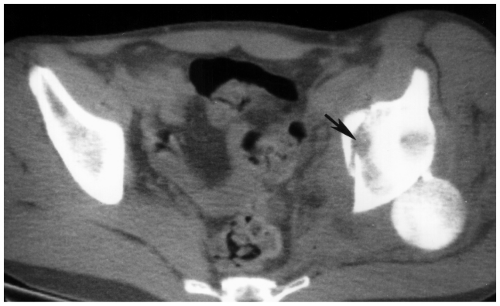 Fig. 4-25 Axial computed tomographic (CT) image in a patient with acetabular fracture (arrow) and posterior dislocation of the femoral head compressing the sciatic nerve. |
The incidence of heterotopic ossifications (HOs) varies from 3% to 69%. In a large series of 23 articles, the average incidence was 26%. Avascular necrosis (AVN) of the femoral head occurs in approximately 6% to 10% of all cases, but the incidence increases when posterior dislocation of the femoral head occurs. Local infection occurs in 4% of cases and deep venous thrombosis or pulmonary embolus in 4% to 8%. Revision surgery is necessary in 8% of patients treated with open reduction and internal fixation.
Suggested Reading
Giannoudis PV, Grotz MRW, Papakostidis C, et al. Operative treatment of displaced pelvic fractures of the acetabulum: A META-analysis. J Bone Joint Surg. 2005;87B:2–9.
Issack PS, Toro JB, Buly RL, et al. Sciatic nerve release following fracture and reconstruction surgery of the acetabulum. J Bone Joint Surg. 2007;89A:1432–1437.
Kaempffe FA, Bone LB, Border JR. Open reduction and internal fixation of acetabular fractures: Heterotopic ossification and other complications of treatment. J Orthop Trauma. 1991;5:439–445.
Matta JM, Merritt PO. Displaced acetabular fractures. Clin Orthop. 1988;230:83–97.
Dislocations and Fracture/Dislocations of the Hip
Dislocations of the hip account for only 5% of all dislocations. High-velocity trauma such as motor vehicle accidents, motorcycle accidents, and fall from significant heights are the major mechanisms of injury. Because of the severity of trauma, multiple injuries are present in 75% of cases. Dislocations may be anterior, central, or posterior. As central dislocations (Fig. 4-24) occur with acetabular fractures described in the preceding text, the author will focus on anterior and posterior dislocations.
Posterior Dislocations
Posterior dislocations of the hip are seven to ten times more common than anterior dislocations. The injury occurs when force is applied to the knee or foot with the hip in the flexed position. Associated posterior acetabular rim or posterior column fractures are common. The degree of involvement of the posterior acetabulum is related to the position of the femur at the time of injury (see Fig. 4-26, also Fig. 4-16). The more abducted the femur, the larger the fragment.
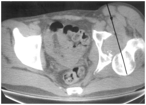 Fig. 4-26 Axial computed tomographic (CT) image following posterior dislocation of the hip demonstrating the direction of the femoral displacement (line with arrow) and the actetabular rim fracture (open arrow) (Thompson and Epstein type IB). |
Classification: Thompson and Epstein with modification
Type IA—dislocation with or without minor rim fracture
Type IB—dislocation with simple posterior wall fracture, which becomes trapped in the joint with reduction (Fig. 4-26)Related posts:

Stay updated, free articles. Join our Telegram channel

Full access? Get Clinical Tree