The Foot and Ankle
This chapter will focus on foot and ankle disorders requiring orthopaedic instrumentation including trauma, common orthopaedic procedures, and joint replacement. Clinical evaluation, treatment options, and complications will be reviewed. Preoperative imaging and imaging of complications will be emphasized.
Trauma
The management of foot and ankle fractures is a common problem for orthopaedic surgeons, emergency physicians, family physicians, and radiologists. Imaging plays an important role in detection and classification of bone and soft tissue injuries so that appropriate treatment plans can be instituted.
Discussion of specific injuries is most easily accomplished by anatomic regions. Therefore, ankle, hind foot, mid foot, and forefoot injuries will be discussed separately.
Ankle Fractures
Approximately 10% of emergency department visits are related to ankle injuries, typically presenting as sprains. The number of ankle injuries in adults (especially those older than 50 years) has been constantly increasing. The highest incidence is in women aged 75 to 84 years. Most fractures involve the lateral malleolus with isolated malleolar fractures accounting for 67% of ankle fractures. Most fractures involve the lateral malleolus with isolated fractures accounting for 67% of ankle fractures. Twenty five percent of ankle fractures are bimalleolar and about 7% trimalleolar. Approximately 2% of adult ankle fractures are open injuries. In children, ankle fractures account for 5% of all skeletal fractures and 15% of physeal injuries. Adult and pediatric ankle fractures are managed somewhat differently and will be reviewed separately.
Adult Ankle Fractures
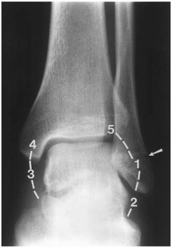 Fig. 8-1 Anteroposterior (AP) radiograph demonstrating the ring concept created by bones and ligaments of the ankle. Common breaks in the ring are (1) the lateral malleolus, (2) lateral ligaments, (3) medial ligaments, (4) medial malleolus, and (5) the distal tibiofibular ligaments and syndesmosis. Note the subtle fracture in the lateral malleolus (arrow). |
When evaluating ankle fractures, an accurate assessment of fracture location, appearance, and displacement is critical. Associated soft tissue or ligament injuries are also important to detect for appropriate management of the injury. When evaluating ankle injuries, it is helpful to consider the bones and ligaments as a ring-like structure. The ring is made of the medial malleolus, tibial plafond, distal tibiofibular ligaments (TFLs) and
syndesmosis, the lateral malleolus, lateral ligament complex, talus, and medial ligaments. Breaks in the ring commonly occur at five sites, either alone or in combination (see Fig. 8-1). Breaks in the ring resulting in asymmetry in the position of the talus in the ankle mortise require fracture or ligament injury involving two of these locations (see Fig. 8-2).
syndesmosis, the lateral malleolus, lateral ligament complex, talus, and medial ligaments. Breaks in the ring commonly occur at five sites, either alone or in combination (see Fig. 8-1). Breaks in the ring resulting in asymmetry in the position of the talus in the ankle mortise require fracture or ligament injury involving two of these locations (see Fig. 8-2).
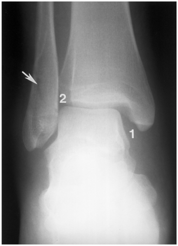 Fig. 8-2 Anteroposterior (AP) radiograph demonstrating widening of the medial ankle mortise (1) due to medial ligament tear, widening of the syndesmosis (2) due to distal tibiofibular ligament and syndesmotic tears, and a subtle (arrow) distal fibular fracture. |
Classifications
Most ankle injuries are the result of inversion (supination) or eversion (pronation) forces. However, the mechanism of injury is rarely pure with rotational, abduction, or adduction forces to the foot and axial loading occurring as well (see Figs. 8-3, 8-4, 8-5, and 8-6). There are multiple classification systems, but the Lauge-Hansen, Danis-Weber, and Orthopaedic Trauma Association systems will be reviewed. Common fracture eponyms will also be listed following the classification section.
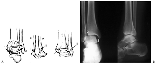 Fig. 8-3 Pronation (eversion)-abduction injury. A: Illustration of the three stages that occur if the force continues. Stage I—transverse fracture of the medial malleolus or deltoid ligament tear. State II: posterior tibial fracture of distal tibiofibular ligament tear. Stage III: Oblique fibular fracture beginning at the joint level and best seen on the anteroposterior (AP) radiograph. Traction forces cause the medial injury and impaction the lateral fracture. B: AP and lateral radiographs demonstrate widening of the ankle mortise medially (1) with no fibular fracture but disruption of the distal tibiofibular ligaments (stage II). |
The Lauge-Hansen classification is based on the position of the foot and direction of the forces at the time of injury. This system is very accurate in predicting associated ligament injuries. Determining the mechanism of injury is based on the appearance of the fibular fracture and position of the talus. Table 8-1 describes the stages of injury and radiographic features of the Lauge-Hansen classification.
The Danis-Weber classification is based on the location of the fibular fracture. Type A fractures are below the level of the ankle joint. Type B fractures are at the level of the ankle with the distal TFLs intact. Type C fractures are above the ankle joint with disruption of the ligaments and syndesmosis (see Fig. 8-7).
The Orthopaedic Trauma Association classification expands upon the Weber, Lauge-Hansen, and AO (Arbeitsgemeinshaft
fur Osteosynthesefragen) classifications with three major groups (A to C) divided into three subgroups with multiple additional subgroups (see Figs. 8-8, 8-9, and 8-10). The features are similar to the classifications mentioned in the preceding text and when appropriate will be included in Table 8-2.
fur Osteosynthesefragen) classifications with three major groups (A to C) divided into three subgroups with multiple additional subgroups (see Figs. 8-8, 8-9, and 8-10). The features are similar to the classifications mentioned in the preceding text and when appropriate will be included in Table 8-2.
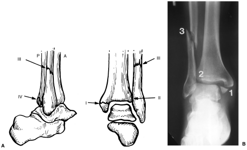 Fig. 8-4 Pronation (eversion)-lateral rotation injury. A: Illustration of the four stages of a pronation-lateral rotation injury. Stage I—deltoid ligament rupture or transverse medial malleolar fracture. Stage II: disruption of the anterior distal tibiofibular ligament and syndesmosis. Stage III: high fibular fracture typically >6 cm above the joint line. Stage IV: posterior tibial fracture or posterior distal tibiofibular ligament tear. B: Anteroposterior (AP) radiograph demonstrating a stage III pronation-lateral rotation injury with a transverse medial malleolar fracture (1), widening of the syndesmosis due to disruption of the anterior distal tibiofibular ligament and syndesmosis (2), and a high fibular fracture (3). |
Chapter 2 contains common fracture eponyms for fractures and ligament injuries involving the ankle.
Tibial Plafond Fractures
Tibial plafond fractures do not fit neatly into the commonly used ankle fracture classifications mentioned earlier. Most (77%) occur in patients younger than 50 years. Fractures are the result of axial loading after falls from significant heights or high-velocity motor vehicle accidents. Fractures usually extend up the tibial shaft in an oblique or spiral manner. Severe comminution with multiple articular fragments (pilon fracture) is common. In addition, 20% of plafond fractures are open.
The Orthopaedic Trauma Association classification of plafond fractures expands the AO classification with subgroups, but Table 8-3 and the illustrations (see Figs. 8-11, 8-12 and 8-13) demonstrate the complexity of these injuries.
Isolated dislocations of the ankle without fractures are rare. Most occur with plantar flexion and inversion resulting in posteromedial dislocations.
Suggested Reading
Arimoto HR, Forrester DM. Classification of ankle fractures: An algorithm. AJR Am J Roentgenol. 1980;135:1057–1063.
Berquist TH. Radiology of the foot and ankle, 2nd ed. Philadelphia: Lippincott Williams & Wilkins; 2000:171–280.
Lauge-Hansen N. Fractures of the ankle. II. Combined experimental-surgical and experimental-radiological investigations. Arch Surg. 1950;60:957–985.
Orthopaedic Trauma Association Committee for Coding and Classification. Fracture and dislocation compendium. J Orthop Trauma. 1996;10:1–155.
Ovadia DN, Beals RK. Fractures of the tibial plafond. J Bone Joint Surg. 1986;68A:543–551.
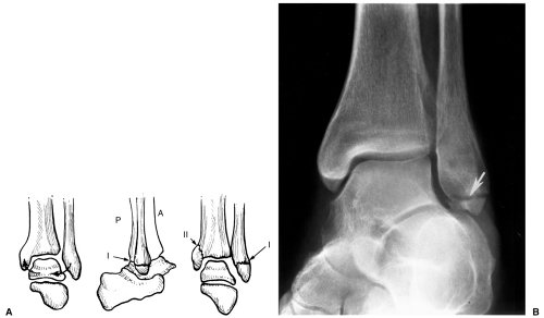 Fig. 8-5 Supination (inversion)-adduction injury. A: Illustration of the two stages of injury. Stage I: lateral ligament tear or transverse fracture of the lateral malleolus below the joint line. Stage II: lateral ligament tear or transverse fracture of the lateral malleolus below the joint line with a steep oblique medial malleolar fracture. B: Mortise view demonstrating a transverse (traction) fracture of the distal lateral malleolus (arrow). |
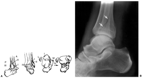 Fig. 8-6 Supination (inversion)-lateral rotation injury. A: Illustration of the four stages of injury. Stage I: disruption of the anterior tibiofibular ligament. Stage II: spiral fracture of the distal fibula best seen on the lateral view. Stage III: above plus disruption of the posterior distal tibiofibular ligament. Stage IV: above plus transverse fracture of the distal medial malleolus. B: Lateral radiograph demonstrating an oblique fibular fracture (arrows) not clearly seen on the anteroposterior (AP) view. |
Table 8-1 LAUGE-HANSEN CLASSIFICATION | ||||||||||||||||||||||||||||||||||||
|---|---|---|---|---|---|---|---|---|---|---|---|---|---|---|---|---|---|---|---|---|---|---|---|---|---|---|---|---|---|---|---|---|---|---|---|---|
|
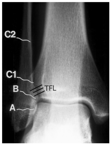 Fig. 8-7 Radiograph demonstrating the Danis-Weber classification for ankle fractures based on the location of the fibular fracture. Type A: below the level of the joint. Type B: at the level of the ankle with tibiofibular ligament (TFL) intact. Type C: above the joint with syndesmotic and distal TFL rupture (C1) and higher fibular fracture (C2). |
Pediatric Ankle Fractures
The appearance of ankle fractures in children depends on the age (growth plate development), relationship of the ligaments, and mechanism of injury. Fractures most commonly occur in boys aged 8 to 15 years. The age cutoff for pediatrics may be arbitrarily set at 18 or when the growth plates are closed. Ligament injuries are unusual in children. The mechanisms of injury are similar to those described in the adult.
Several classification systems are commonly used including the Salter-Harris (see Fig. 8-14 and Table 8-4) and the Dias-Tachdjian (see Fig. 8-15 and Table 8-5) classifications. The latter is similar to the Lauge-Hansen system with integration of the Salter-Harris classification.
Two additional pediatric injuries include the juvenile Tillaux fracture and triplane fractures. The distal tibial growth plate fuses medial to lateral placing the lateral physis at greater risk in adolescents. With external rotation forces, the distal TFL displaces the lateral epiphysis resulting in a Salter-Harris III fracture of the lateral tibia (see Fig. 8-16).
Triplane fractures are more complex physeal fractures resulting in poorer prognosis. These injuries account for 5% to 7% of ankle fractures in children. Triplane fractures have components in the sagittal, coronal, and axial planes which may result in two- (see Fig. 8-17), three-, or four-part fractures. Three-part fractures differ from two-part fractures in that an additional fracture line separates the anterolateral epiphyseal fragment from the posteromedial tibial fragment (see Fig. 8-18).
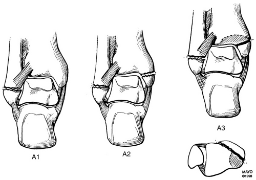 Fig. 8-8 AO (Arbeitsgemeinshaft fur Osteosynthesefragen)/Orthopaedic Trauma classification. Type A: infrasyndesmotic fractures. Type A1: isolated malleolar fracture below the syndesmosis (see also Lauge-Hansen supination-adduction Stage I in Fig. 8-5B). Type A2: medial and lateral malleolar fractures below the syndesmosis. Type A3: medial and lateral malleolar fractures with a posteromedial tibial fragment. |
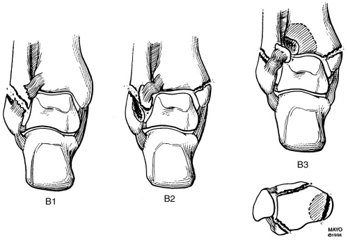 Fig. 8-9 AO (Arbeitsgemeinshaft fur Osteosynthesefragen)/Orthopaedic Trauma classification. Type B: transsyndesmotic fractures. Type B1: isolated lateral malleolar fracture at the syndesmosis. Type B2: with associated medial malleolar fracture. Type B3: bimalleolar with avulsions of the anterior and posterior tibiofibular ligaments. |
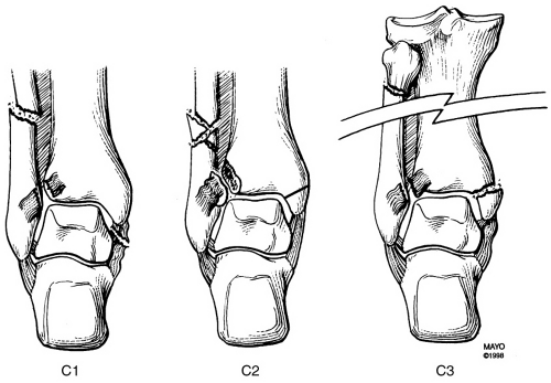 Fig. 8-10 AO (Arbeitsgemeinshaft fur Osteosynthesefragen)/Orthopaedic Trauma Association. Type C: fibular fracture well above the syndesmosis. Type C1: fibular fracture in the distal diaphysis with associated syndesmotic and medial ligament tears (see also Lauge-Hansen pronation-lateral rotation stage III in Fig. 8-4). Type C2: similar to C1, but with complex fibular fracture. Type C3: similar secondary features with proximal fibular fracture and more extensive interosseous membrane disruption. |
Table 8-2 ORTHOPAEDIC TRAUMA ASSOCIATION CLASSIFICATION ANKLE FRACTURES | ||||||||||||||||||||||||||
|---|---|---|---|---|---|---|---|---|---|---|---|---|---|---|---|---|---|---|---|---|---|---|---|---|---|---|
|
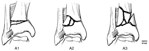 Fig. 8-11 Orthopaedic Trauma Association classification for tibial plafond fractures. Type A: extra-articular. Type A1: simple metaphyseal. Type A2: metaphyseal wedge. Type A3: metaphyseal complex. |
Table 8-3 ORTHOPAEDIC TRAUMA ASSOCIATION CLASSIFICATION TIBIAL PLAFOND FRACTURES | ||||||||||||||||||||||||||
|---|---|---|---|---|---|---|---|---|---|---|---|---|---|---|---|---|---|---|---|---|---|---|---|---|---|---|
|
Suggested Reading
Cooperman DR, Spiegel PG, Laros CG. Tibial fractures involving the ankle in children: The so-called triplane epiphyseal fracture. J Bone Joint Surg. 1978;60A:1040–1046.
Dias LS, Tachdjian MO. Physeal injuries to the ankle in children: Classification. Clin Orthop. 1978;136:230–233.
Kay RM, Matthys GA. Pediatric ankle fractures: Evaluation and treatment. J Am Acad Orthop Surg. 2001;9:268–278.
Imaging Evaluation
Ankle radiographs account for 10% of all radiographs requested in the emergency department. In many cases, an adequate physical examination is not performed before ordering radiographs. Following the Ottowa ankle rules, imaging should be performed if the patient has the following findings: (a) inability to bear weight; (b) point tenderness over the medial malleolus, or posterior edge or inferior tip of the lateral malleolus, or talus or calcaneus; and (c) inability to ambulate for four steps in the emergency department.
At most institutions and according to the American College of Radiology appropriateness criteria, anteroposterior (AP), lateral, and mortise radiographs should be obtained if patients meet the Ottowa ankle rules. Additional views or radiographs of the foot may be obtained as indicated.
Patients with a joint effusion frequently have a subtle, easily overlooked fracture. In fact, fractures that may mimic ankle sprains need to be considered and include the base of the fifth metatarsal, anterior calcaneal process fractures, talar dome fractures, and lateral and posterior talar process fractures. Up to 50% of talar dome and process fractures are overlooked on radiographs. When an effusion is present or there is question about a possible fracture, computed tomography (CT) with thin sections and reformatting for complete evaluation are recommended. CT may also be required to classify complex adult fractures and physeal fractures in children. Magnetic resonance imaging (MRI) is rarely warranted in the acute setting, but is useful for evaluating soft tissue structures and more subtle marrow changes if symptoms persist.
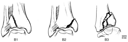 Fig. 8-12 Orthopaedic Trauma Association classification for tibial plafond fractures. Type B: partial articular. Type B1: pure split. Type B2: split with depression. Type B3: complex depression. |
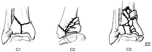 Fig. 8-13 Orthopaedic Trauma Association classification for tibial plafond fractures. Type C: complex articular. Type C1: articular simple. Type C2: articular simple, complex metaphyseal. Type C3: complex articular. |
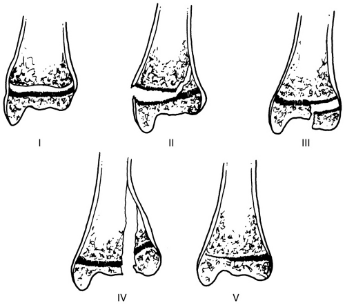 Fig. 8-14 Illustration of the Salter-Harris classification for physeal injuries. Type I: fracture through and isolated to the growth plate. Type II: growth plate fracture extending through the metaphysic. Type III: growth plate fracture extending through the epiphysis. Type IV: fracture extending through the metaphysic, physis, and epiphysis. Type V: growth plate compression. |
Table 8-4 SALTER-HARRIS CLASSIFICATION | ||||||||||||||
|---|---|---|---|---|---|---|---|---|---|---|---|---|---|---|
| ||||||||||||||
Suggested Reading
Dalinka MK, Alazraki NP, Daffner RH, et al ACR appropriateness criteria for suspected ankle fractures. Am Coll Radiol. 2005:1–4.
Magid D, Michelson JD, Ney DR, et al Adult ankle fractures: Comparison of plain films and interactive two- and three-dimensional CT scans. AJR Am J Roentgenol. 1990;154:1017–1023.
Stiell IG, McKnight RD, Greenberg GH, et al Implementation of the Ottowa ankle rules. JAMA. 1993;269:1127–1132.
Treatment Options for Ankle Fractures
Treatment approaches vary with the type of injury, degree of displacement, and whether there is still significant growth potential in children (≤2 years remaining). In adults, the goals of treatment are accurate anatomic reduction, parallel articular surface, and early motion to reduce stiffness or adhesive capsulitis.
Fractures of the medial or lateral malleolus without secondary fracture or ligament injury may be treated conservatively with closed reduction if displacement is <2 mm. Immobilization for 6 weeks is usually adequate. If displacement exceeds 2 mm, internal fixation is indicated. Medial malleolar fractures can be treated with one or two cannulated screws or malleolar screws, K-wire, and tension band or bioabsorbable fixation devices. Placement of malleolar screws is important to avoid abutment with the posterior tibial tendon (see Fig. 8-19). Fibular fractures can be treated with interfragmentary screws or plate and screw fixation (see Fig. 8-20).
When both malleoli are involved a similar approach is used in both structures. A syndesmotic screw may also be required to secure the distal tibiofibular relationship when the ligament is disrupted (Lauge-Hansen pronation–lateral rotation). The screw should not be too tightly placed as complications may result. Also, if the screw is too proximal the tibia may displace laterally. Posterior tibial fragments are usually fixed internally with one or more screws if they involve >25% of the articular surface.
Tibial plafond fractures (Figs. 8-11, 8-12 and 8-13) are particularly difficult to manage (see Fig. 8-21). Significant separation of the fragments and loss of articular cartilage may be present. CT with reformatting in the coronal and sagittal planes or three-dimensional reconstruction may be required to plan the surgical approach. Bone grafting may be required to support the articular surface and to fill in bone voids. It is not unusual (15%) to proceed to arthrodesis in more complex injuries.
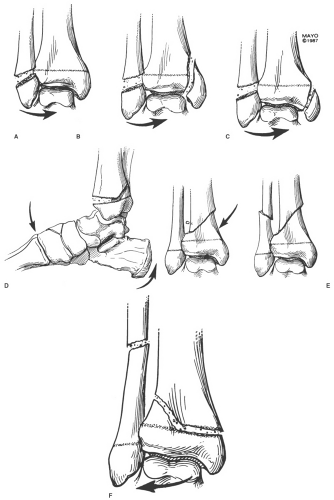 Fig. 8-15 Illustration of the Dias-Tachdjian classification of pediatric ankle fractures combining the Lauge-Hansen and Salter-Harris classifications. A–C: Supination-inversion injures. Stage I: Salter-Harris I or II fibular fracture. Stage II: Salter-Harris I or II fibular fracture with steep oblique medial malleolar fracture (Type IV Salter-Harris in this case). D: Supination-plantar flexion injury: Salter-Harris I or II of the tibia best seen on the lateral view. E: Supination-external rotation injury: Stage I: Salter-Harris II or oblique fracture of the distal tibia; Stage II: Stage I plus fibular fracture well above the growth plate. F: Pronation–eversion-external rotation injury. Salter-Harris II of the tibia plus high fibular fracture. |
Table 8-5 DIAS-TACHDJIAN CLASSIFICATION FOR PEDIATRIC ANKLE FRACTURES | ||||||||||||||||||||||||||
|---|---|---|---|---|---|---|---|---|---|---|---|---|---|---|---|---|---|---|---|---|---|---|---|---|---|---|
| ||||||||||||||||||||||||||
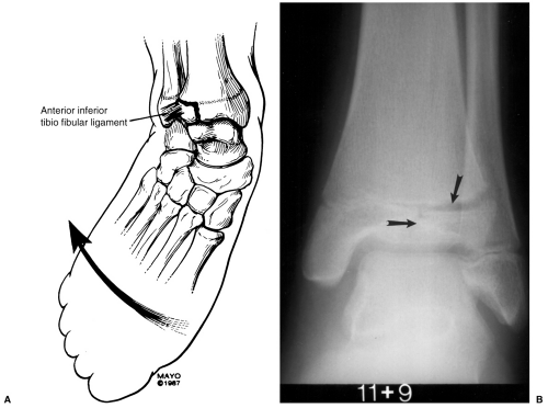 Fig. 8-16 Juvenile Tillaux fracture. A: Illustration of the mechanism of injury with external rotation of the foot causing avulsion of the lateral tibial epiphysis. B: Anteroposterior (AP) radiograph of a juvenile Tillaux fracture (arrows). |
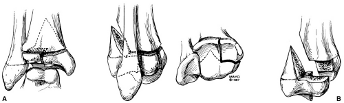 Fig. 8-17 Two-part triplane fracture. A: Coronal and sagittal plane illustrations. B: Axial plane and separated fragments. |
Pediatric ankle fractures are approached differently, especially if there is significant growth potential remaining. Physeal fracture should be reduced with care to avoid further damage to the growth plate. In most cases, closed techniques with a short leg cast or brace yields good results. Isolated fibular fractures heal in approximately 3 weeks. When the tibia is also involved it can be reduced and the fibula realigns.
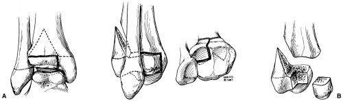 Fig. 8-18 Three-part triplane fracture. A: Coronal and sagittal plane illustrations. B: Axial plane and separated fragments. |
Salter-Harris I and II tibial fractures with <2 mm displacement can be treated with cast immobilization for 4 to 6 weeks. If reduction cannot be maintained or the displacement exceeds 2 mm, cannulated screws or K-wires can be placed parallel to the physis. Similar approaches can be used for displaced (>2 mm) Salter-Harris III, triplane, and juvenile Tillaux fractures (see Fig. 8-22). Physeal compression injuries are uncommon. In this setting, excision of the damage growth plate and bone grafting may be required. Leg length discrepancy may be an issue that can be dealt with later as indicated.
Suggested Reading
Femino JE, Gruber BF, Karunakar MA. Safe zone for placement of medial malleolar screws. J Bone Joint Surg. 2007;89A:133–138.
Kay RM, Matthys GA. Pediatric ankle fractures: Evaluation and treatment. J Am Acad Orthop Surg. 2001;9:268–278.
Ovadia DN, Beals RK. Fractures of the tibial plafond. J Bone Joint Surg. 1986;68A:543–551.
Tejwani NC, McLauring TM, Walsh M, et al Are outcomes of bimalleolar fractures poorer than those of lateral malleolar fractures with medial ligamentous injury? J Bone Joint Surg. 2007;89A:1438–1441.
Imaging of Ankle Fracture Complications
Complications vary in children and adults and may be related to the initial injury or treatment method selected. For example, bimalleolar fractures have a poorer prognosis than isolated malleolar fractures. In adults, the most common complication is
posttraumatic arthrosis, which occurs in 30% to 40% of cases. The incidence is highest in complex plafond fractures, when the syndesmosis is not adequately reduced and in older patients. Serial radiographs are adequate for diagnosis, although in certain cases CT or even MRI may be required before consideration of ankle fusion (see Fig. 8-23).
posttraumatic arthrosis, which occurs in 30% to 40% of cases. The incidence is highest in complex plafond fractures, when the syndesmosis is not adequately reduced and in older patients. Serial radiographs are adequate for diagnosis, although in certain cases CT or even MRI may be required before consideration of ankle fusion (see Fig. 8-23).
 Fig. 8-19 Anteroposterior (AP) (A) and lateral (B) radiographs of a healed medial maleollar fracture with two malleolar fixation screws. Broken lines indicate the malleolar margins with the three zones divided by vertical lines. Zone 1 is the safe zone. Zone 2 is within 2 mm of the posterior tibial tendon increasing the risk of tendon abutment. Screws placed in zone 3 will likely cause abutment. In this case the anterior screws are in zones 2 and 3. |
Ankle pain related to internal fixation hardware occurs in up to 31% of patients. This may be related to superficial or deep soft tissue irritation or bony impingement. Up to 23% of patients with internal fixation request removal of the hardware. However, symptomatic improvement occurs in only 50% of the cases. Hardware failure with plate fracture or screw pullout may also cause pain. Overcorrection or cross-union may also occur with syndesmotic screws. This may be obvious on radiographs, but may require CT or MRI for confirmation and syndesmotic evaluation (see Fig. 8-24).
Malunion, delayed union, and nonunion are uncommon. In a larger series of 260 patients, the incidence of nonunion was <1%. Nonunion is reported to occur more frequently with medial malleolar fractures (10% to 15%) (see Fig. 8-25). The incidence is much higher with closed reduction compared to internal fixation. Evaluation of healing can be accomplished with CT or MRI in subtle cases.
Reflex sympathetic dystrophy is a syndrome of refractory pain, neurovascular changes of swelling, and vasomotor instability affecting the bone and soft tissues. The etiology is unclear. Most consider the syndrome related to posttraumatic reflex spasm leading to loss of vascular tone and aggressive osteoporosis. Osteoporosis may be patch or diffuse involving cortical and medullary bone. Radionuclide bone scans may demonstrate impressive changes early (see Fig. 8-26). Table 8-6 lists complications of adult ankle fractures and imaging approaches.
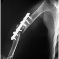
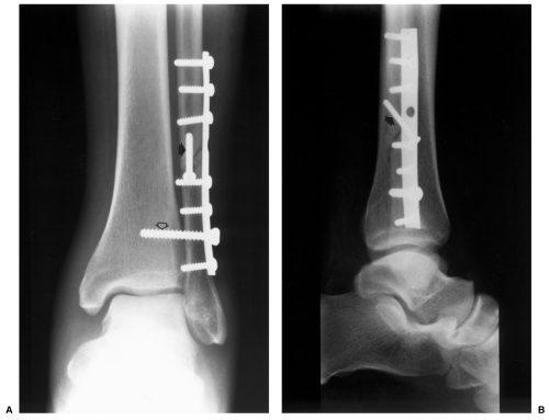 Fig. 8-20 Anteroposterior (AP) (A) and lateral (B) radiographs with one third tubular plate and cortical screw fixation of a high fibular fracture. There is also an interfragmentary screw (arrow) and a syndesmotic screw (open arrow) to reduce the ligament and interosseous membrane disruption. |
Pediatric ankle fracture complications can be similar, but are more often related to the patient age and status of the growth plates. The most common problem is premature or asymmetric closure of the growth plates (see Fig. 8-27). Salter-Harris III and IV fractures of the tibia have the poorest prognosis resulting in leg length discrepancy and joint asymmetry. Leg length discrepancy >1 to 2 cm may require lengthening of the involved extremity or epiphysodesis of the contralateral tibia. In patients with asymmetric physeal closure, the bony bar may be excised if it involves <50% of the growth plate. Angular deformities >10 degrees may be treated with wedge osteotomy.
Spiegel et al. divided physeal fractures into three groups based on complication rates. Low-risk (Salter-Harris I and II fibular fractures and type I tibial fractures) injuries had a 6.7% complication rate. High-risk fractures included type III and IV tibial fractures with >2 mm displacement, juvenile Tillaux fractures, comminuted epiphyseal fractures, and type V fractures (32% complication rate). Type II tibia fractures were considered more unpredictable with a 16.7% complication rate.
Long-term osteoarthritis is also more common with Salter-Harris III and IV fractures (29%) compared to lesser injuries (12%). Serial radiographs are usually adequate to follow these
patients. Ankle stiffness due to bone and soft tissue injury occurs in approximately 6% of patients.
patients. Ankle stiffness due to bone and soft tissue injury occurs in approximately 6% of patients.
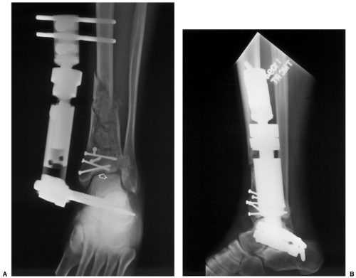 Fig. 8-21 Anteroposterior (AP) (A) and lateral (B) radiographs following reduction of a complex tibial fracture involving the plafond. There is slight articular deformity (open arrow) following screw fixation of the distal tibial fragments and external fixation to maintain tibial length. |
Reflex sympathetic dystrophy also occurs in children and is much more common in females (up to 84% of patients).
Suggested Reading
Brown OL, Dirschl DR, Obremskey WT. Incidence of hardware-related pain and its effect on functional outcomes after open reduction and internal fixation of ankle fractures. J Orthop Trauma. 2001;15:271–274.
Femino JE, Gruber BF, Karunakar MA. Safe zone for placement of medial malleolar screws. J Bone Joint Surg. 2007;89A:133–138.
Kay RM, Matthys GA. Pediatric ankle fractures: Evaluation and treatment. J Am Acad Orthop Surg. 2001;4:268–278.
Spiegel PG, Cooperman DR, Laros GS. Epiphyseal fractures of the distal ends of the tibia and fibula. J Bone Joint Surg. 1978;60A:1046–1050.
Tejwani NC, McLaurin TM, Walsh M, et al Are outcomes of bimalleolar fractures poorer than those of lateral malleolar fractures with medial ligament injury? J Bone Joint Surg. 2007;89A:1438–1441.
Talar Fractures and Dislocations
Talar fractures account for <1% of all skeletal fractures. However, the talus is the second most common tarsal fracture after the calcaneus. Talar fractures are rare in children compared to adults. Less than 1% of all pediatric fractures and 2% of foot fractures involve the talus. In adults, talar neck fractures account for 30% to 50% of talar fractures, followed by talar body fractures (40%) and associated dislocations (15%). Talar head fractures account for 3% to 10% of talar fractures. Subtalar dislocations account for only 1.3% of all dislocations. Fractures of the talar dome, posterior process, and lateral talar process (snowboarder’s fracture) may be subtle. In fact, up to 50% are initially overlooked on radiographs.
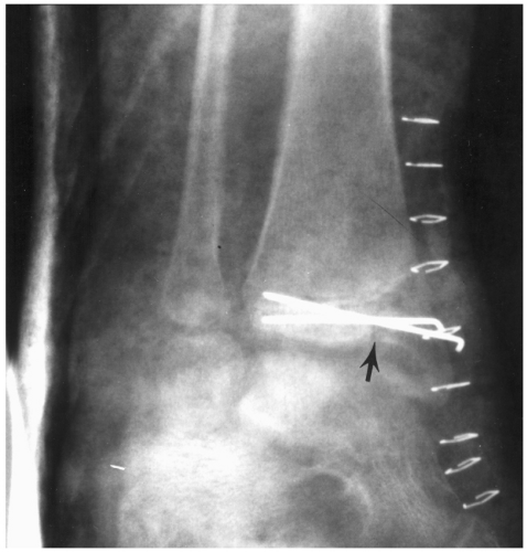 Fig. 8-22 Posttraumatic arthrosis. Anteroposterior (AP) (A) and lateral (B) radiographs demonstrate posttraumatic arthritis on the right. The patient was treated with ankle arthrodesis with screw fixation and fibular osteotomy with buttress graft (C and D). |
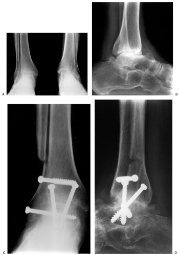 Fig. 8-23 Mortise view of the ankle with K-wire fixation of a Salter-Harris III (arrow) medial malleolar fracture. The wires are placed parallel to, but not through, the growth plate. |
There are certain key features regarding the talus. First, its articulations account for 90% of the motion in the ankle and foot. Also, due to the extensive articular surface area the vascular supply is tenuous. Therefore, avascular necrosis (AVN) is not uncommon, especially following displaced talar neck fractures.
Talar Neck Fractures
Talar neck fractures account for 30% to 50% of talar fractures and 6% of all foot and ankle injuries. Fractures are the
result of abrupt dorsiflexion of the foot impacting the talus against the tibia. Injuries typically occur during motor vehicle accidents or significant falls. Supination-lateral rotation injuries may also result in talar neck fracture. Associated fractures are not uncommon. Up to 26% of patients have associated fractures of the medial malleolus and 15% have talar head fractures with associated fractures of the medial and lateral malleoli.
result of abrupt dorsiflexion of the foot impacting the talus against the tibia. Injuries typically occur during motor vehicle accidents or significant falls. Supination-lateral rotation injuries may also result in talar neck fracture. Associated fractures are not uncommon. Up to 26% of patients have associated fractures of the medial malleolus and 15% have talar head fractures with associated fractures of the medial and lateral malleoli.
The Orthopaedic Trauma Association classification considers talar neck fractures as extra-articular. A common classification is the Hawkins classification (see Fig. 8-28).
Talar Body Fractures
There is a wide range of talar body fractures including osteochondral fractures, talar process fractures, and complex crush or shearing fractures. Table 8-7 summarizes the incidence and mechanism of injury of talar body fractures.
Lateral talar process and talar dome fractures are overlooked on initial radiographs in up to 50% of patients. Talar dome fractures are more common and may involve the lateral or medial talar dome or both simultaneously. Medial lesions are deeper and not always associated with acute trauma (see Fig. 8-29). Lateral lesions are more subtle and flake-like
(see Fig. 8-30). The Berndt and Harty classification is applied to talar dome fractures. Stage I lesions are compressions of the talar dome without associated ligament ruptures and intact overlying cartilage. Stage II lesions are partially elevated fractures. Stage III lesions are complete fractures without displacement and stage IV lesions are displaced. Stage II to IV lesions can be easily overlooked due to the associated ligament injuries.
(see Fig. 8-30). The Berndt and Harty classification is applied to talar dome fractures. Stage I lesions are compressions of the talar dome without associated ligament ruptures and intact overlying cartilage. Stage II lesions are partially elevated fractures. Stage III lesions are complete fractures without displacement and stage IV lesions are displaced. Stage II to IV lesions can be easily overlooked due to the associated ligament injuries.
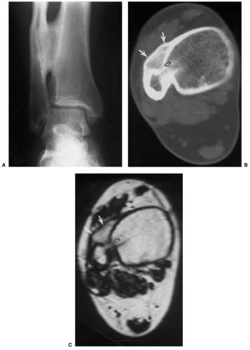 Fig. 8-24 Syndesmotic cross-union. Anteroposterior (AP) (A) radiograph demonstrates an old healed fibular fracture with cross-union of the tibia and fibula. Axial computed tomography (CT) (B) and T1-weighted magnetic resonance (MR) images show the bony union (arrows) and the prior syndesmotic screw tract (open arrow). |
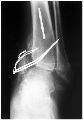 Fig. 8-25 Medial malleolar fracture treated with K-wire and tension band with nonunion and marked asymmetry of the ankle mortise. |
Talar Head Fractures
Talar head fractures are uncommon, although some reports indicate that they account for 3% to 10% of talar fractures. Fractures may be easily overlooked on radiographs. Injuries result from extreme dorsiflexion of the foot or associated with subtalar dislocations when the talar head is impacted against the navicular.
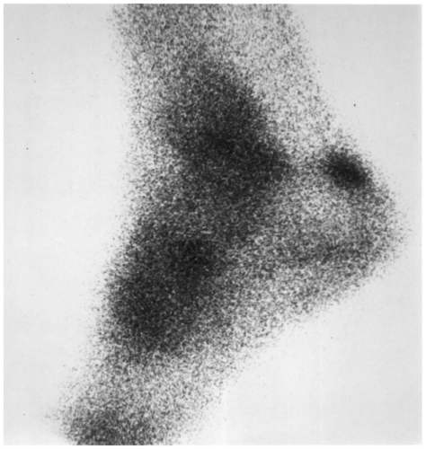 Fig. 8-26 Reflex sympathetic dystrophy. Technetium Tc 99m methylene diphosphonate (MDP) bone scan demonstrate increased tracer in the ankle and mid foot. |
Suggested Reading
Berndt AL, Harty M. Transchondral fractures (osteochondritis dissecans) of the talus. J Bone Joint Surg. 1959;41A:988–1020.
Canale ST, Kelly FB. Fractures of the neck of the talus. J Bone Joint Surg. 1978;60A:143–156.
Fortin PT, Balazsy JE. Talus fractures: Evaluation and treatment. J Am Acad Orthop Surg. 2001;9:114–127.
Hawkins LG. Fractures of the neck of the talus. J Bone Joint Surg. 1970;52A:991–1002.
Kay RM, Tang CW. Pediatric foot fractures: Evaluation and treatment. J Am Acad Orthop Surg. 2001;9:308–319.
Valderrabono V, Perreu T, Ryf C, et al “Snowboarders” talus fracture-treatment outcome of 20 cases after 3.5 years. Am J Sports Med. 2005;33:871–880.
Imaging of Talar Fractures
Imaging of talar fractures begins with routine AP, lateral, and oblique views of the foot and ankle (see Fig. 8-31). Both internal and external oblique views of the ankle may be helpful for subtle fractures (see Fig. 8-32). Special subtalar oblique projections have also been described. However, if radiographs are equivalent or fractures are defined, most institutions obtain CT with coronal and sagittal reformatting or three-dimensional
reconstructions to fully evaluate the fracture and articular involvement (see Fig. 8-33). CT is particularly important in subtle injuries. The presence of a joint effusion (best seen on the lateral view) should suggest further imaging (CT or MRI) to exclude subtle injuries to the talar dome or talar processes. MRI is useful for detection of subtle stress injuries, bone bruises, early AVN, and soft tissue injuries (see Fig. 8-34).
reconstructions to fully evaluate the fracture and articular involvement (see Fig. 8-33). CT is particularly important in subtle injuries. The presence of a joint effusion (best seen on the lateral view) should suggest further imaging (CT or MRI) to exclude subtle injuries to the talar dome or talar processes. MRI is useful for detection of subtle stress injuries, bone bruises, early AVN, and soft tissue injuries (see Fig. 8-34).
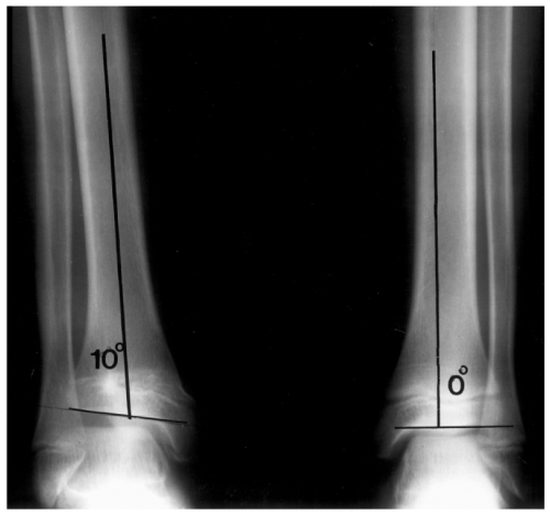 Fig. 8-27 Standing radiographs of the legs with parallel articular surfaces on the left and 10-degree angular deformity on the right due to premature closure laterally. |
Table 8-6 IMAGING OF ADULT FRACTURE COMPLICATIONS | ||||||||||||||||||
|---|---|---|---|---|---|---|---|---|---|---|---|---|---|---|---|---|---|---|
| ||||||||||||||||||
Table 8-7 TALAR BODY FRACTURES | |||||||||||||||
|---|---|---|---|---|---|---|---|---|---|---|---|---|---|---|---|
|
Suggested Reading
Berquist TH. Radiology of the foot and ankle, 2nd ed. Philadelphia: Lippincott Williams & Wilkins; 2000:171–280.
DeSmet AA, Fisher DR, Burnstein MI, et al Value of MR imaging in staging osteochondral lesions of the talus (osteochondritis dissecans): Results in 14 patients. AJR Am J Roentgenol. 1990;154:555–558.
Treatment Options
Treatment options vary with the type of injury, articular involvement, open wounds, patient condition, and surgical preference. Both closed reduction and open reduction with internal fixation may be used in the appropriate settings.
Treatment of talar neck fractures varies with the extent of the lesion. Type I undisplaced fractures or minimally displaced type II injuries can be managed with cast immobilization for 6 weeks. Open reduction and internal fixation is preferred for failed closed reduction of type II and initial treatment of type III and IV lesions (Fig. 8-31). Twenty-five percent of type III fractures are open, thereby increasing the risk of infection. In this setting, internal fixation with delayed wound closer to 3 to 5 days is preferred.
Complex talar body fractures have a high complication rate with closed reduction (see Fig. 8-35). Therefore, open reduction with internal fixation is preferred to restore articular anatomy and preserve as much function as possible.
Talar dome and process fractures are frequently overlooked. Talar process fractures (lateral or posterior) can be managed with cast immobilization if there is <2 mm of displacement. Comminuted fractures may require removal of the small fragments with internal fixation or major fragments. Talar dome fractures that are undisplaced (types I to III) may be treated conservatively. If closed reduction fails, arthroscopic drilling of type II and debridement of type III lesions should be considered. Displaced fragments (type IV) usually result in chronic symptoms and should be removed (see Fig. 8-36).
Talar head fractures with minimal articular deformity or involving only a small portion of the articular surface may be managed with cast immobilization for 6 weeks. If the fragment is displaced or causes incongruency of the talonavicular joint, open reduction and internal fixation with screws or bioabsorbable pins is preferred (see Fig. 8-37).
Isolated dislocations or those associated with other injuries are managed with immobilization that is in concert with treatment of the other injuries. CT images should be obtained following reduction to fully evaluate the joint spaces and any osteochondral fragments that may not have been initially recognized.
 Fig. 8-28 Illustration of the Hawkins classification for talar neck fractures. A: Type I—undisplaced neck fracture. B: Type II—neck fracture with subluxation or dislocation of the subtalar joint. C: Type III—fracture of the neck with displacement of the body from both the ankle and subtalar joints. D: Type IV—fracture of the neck with dislocation with ankle or subtalar subluxation/dislocation and talonavicular subluxation/dislocation. |
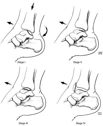 Fig. 8-29 Illustration of the mechanism of injury of medial talar dome fractures. The injury occurs with plantar flexion, axial loading, and inversion-lateral rotation. Stage I—compression, stage II—fracture with partial elevation, stage III—complete fracture with no displacement, and stage IV—displaced fracture. (From Berquist TH. Radiology of the foot and ankle, 2nd ed. Philadelphia: Lippincott Williams & Wilkins; 2000.) |
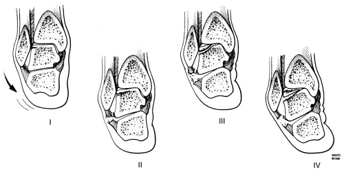 Fig. 8-30 Illustration of the mechanism of injury and classification of lateral talar dome fractures. Inversion causes the lateral talar dome to impact on the fibula. Stage I—compression injury, stage II—partial elevation with lateral ligament tear, stage III—complete fracture without displacement and ligament tear, and stage IV—displaced fracture with ligament tear. (From Berquist TH. Radiology of the foot and ankle, 2nd ed. Philadelphia: Lippincott Williams & Wilkins; 2000.) |
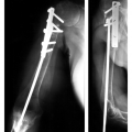
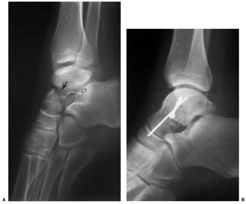 Fig. 8-31 Hawkins type II talar neck fracture. A: Lateral radiograph demonstrates a displaced talar neck fracture (arrow) with subluxation of the subtalar joint (open arrow). The fracture was treated (B) with open reduction using a K-wire and screw for fixation. |
Suggested Reading
Canale ST, Kelly FB. Fractures of the neck of the talus. J Bone Joint Surg. 1978;60A:143–156.
Fortin PT, Balazsy JE. Talus fractures: Evaluation and treatment. J Am Acad Orthop Surg. 2001;9:114–127.
Imaging of Complications
Complications following talar fracture/dislocations include AVN, posttraumatic arthritis, malunion or nonunion, and infection. AVN is common following displaced talar neck fractures and complex talar body fractures. The incidence of AVN is only 0% to 13% with Hawkins type I fractures, but increases to 20% to 58% with type II and 83% to 100% with type IV fractures (see Table 8-8). The incidence of AVN with complex body fractures is 40%. AVN is less common with talar process and talar dome fractures. Radiographs following fractures may demonstrate changes of AVN within 6 to 8 weeks. Normally, there is subchondral osteopenia due to hyperemia. When this is absent or bone sclerosis is evident (Hawkins sign), the area is ischemic (see Fig. 8-38). MRI is more specific and can demonstrate changes earlier (see Fig. 8-39).
Posttraumatic arthrosis involving the tibiotalar and subtalar joints is common following all types of talar fractures. Following complex talar body fractures (Fig. 8-35) the incidence ranges from 48% to 90%. Arthrosis occurs in 54% of patients with talar neck fractures and 50% with talar dome fractures. Serial radiographs are usually adequate for evaluation. However, based on the symptoms and when arthrodesis is considered, CT with coronal and sagittal reformatting is useful for treatment planning purposes.
Fracture healing may be delayed or result in malunion or nonunion. Nonunion occurs in only 4% of patients with
talar neck fractures, although delayed union is common (15%). Delayed union is considered in fractures that have not healed by 6 months. Malunion following talar neck fractures is also common (32%). CT is preferred to evaluate healing in patients with talar fractures.
talar neck fractures, although delayed union is common (15%). Delayed union is considered in fractures that have not healed by 6 months. Malunion following talar neck fractures is also common (32%). CT is preferred to evaluate healing in patients with talar fractures.
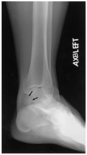 Fig. 8-32 Subtle posteromedial talar fracture (arrows) seen only on the external oblique view. |
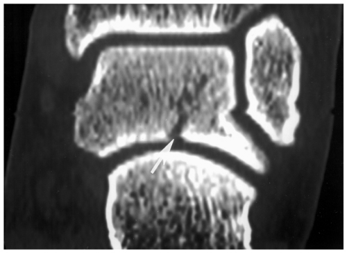 Fig. 8-33 Coronal reformatted computed tomographic (CT) image of a talar body fracture (arrow) with subtalar joint involvement. |
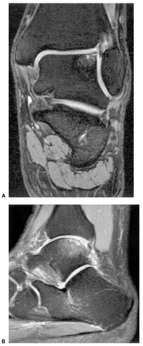 Fig. 8-34 Coronal (A) and sagittal (B) fat-suppressed fast spin-echo T2-weighted sequences demonstrating a talar dome fracture medially. At least two image planes are important to evaluate the size of the lesion and overlying articular cartilage. |
Infection is a relatively common problem due to the incidence of open wounds associated with talar fracture dislocations. More than 50% of Hawkins type III and IV fractures are associated with open wounds. Infection and skin slough are the most difficult complications to manage. Implant removal and placement of antibiotic spacers may be required for treatment. MRI or combined technetium Tc 99m and labeled white blood cells or antigranulocyte antibodies are useful to define infection. Aspirations can also be used to isolate the organisms.
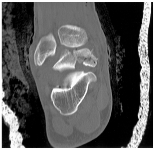 Fig. 8-35 Coronal computed tomographic (CT) image demonstrating a complex talar body fracture with extensive tibiotalar and subtalar articular deformity. |
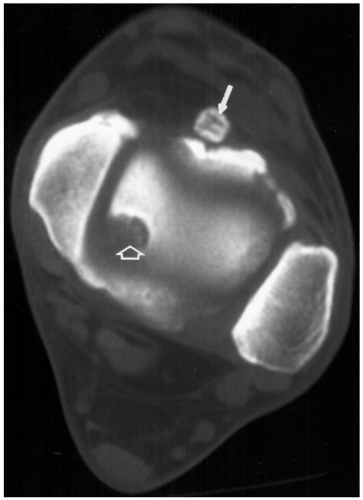 Fig. 8-36 Type IV talar dome lesion. Axial computed tomographic (CT) image demonstrates an osteochondral defect (open arrow) with the displaced fragment anteriorly (arrow). |
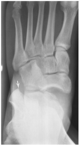 Fig. 8-37 Radiograph of a complex Hawkins IV fracture with talonavicular dislocation and a large displaced talar head fragment (arrow). |
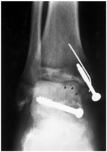 Fig. 8-38 Anteroposterior (AP) radiograph following reduction of a talar neck fracture with a single screw and internal fixation of the associated medial malleolar fracture. Note the subchondral osteopenia (small arrowheads) in the vascularized portion of the talus and the sclerotic appearance laterally due to avascular necrosis (AVN). |
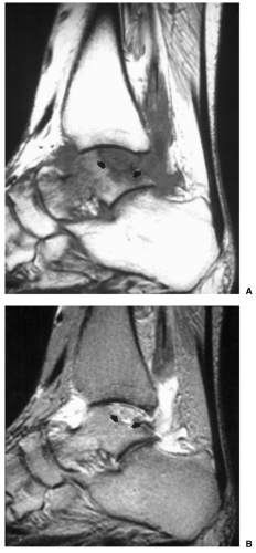 Fig. 8-39 Avascular necrosis (AVN) of the talus. A: Sagittal T1- and T2-weighted (B) images demonstrating a focal area of AVN (arrows). |
Table 8-8 HAWKINS CLASSIFICATION FOR TALAR NECK FRACTURES | |||||||||||||||
|---|---|---|---|---|---|---|---|---|---|---|---|---|---|---|---|
|
Suggested Reading
Berquist TH. Radiology of the foot and ankle, 2nd ed. Philadelphia: Lippincott Williams & Wilkins; 2000:171–280.
Canale ST, Kelly FB. Fractures of the neck of the talus. J Bone Joint Surg. 1978;60A:143–156.
Fortin PT, Balazsy JE. Talus fractures: Evaluation and treatment. J Am Acad Orthop Surg. 2001;9:114–127.
Vallier HA, Nork SE, Benirschke SK, et al Surgical treatment of talar body fractures. J Bone Joint Surg. 2003;86A:1711–1724.
Calcaneal Fractures
The calcaneus is the most commonly fractured tarsal bone, but accounts for only 2% of all skeletal fractures. All age-groups are affected with 5% occurring in children. Extra-articular fractures are more common in children compared to adults. The mechanism of injury may be a fall from a significant height which results in bilateral calcaneal fractures in 5% to 9% and associated thoracic or lumbar compression fractures in 10% of patients. Fractures also occur in motor vehicle accidents. Other associated injuries include ankle fractures (25%), compartment syndrome (10%), peroneal tendon dislocation, and flexor hallucis longus entrapment between bone fragments. Fracture patterns may be intra-articular (70% to 75%) or extra-articular (25% to 30%).
Extra-articular Fractures (25% to 30%)
Extra-articular fractures include all fractures that do not involve the posterior facet. Injuries may be caused by twisting, avulsion, or compression forces. The posterior, anterior, or medial calcaneus may be involved. Patients with anterior calcaneal process fractures often present with symptoms similar to ankle sprain. Therefore, it is not uncommon for these fractures to be overlooked (see Fig. 8-40).
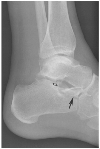 Fig. 8-40 Lateral radiograph demonstrating an anterior calcaneal process fracture (arrow). There is also a subtle talar articular fracture (open arrow). |
Fractures of the calcaneal body spare the facets, but may result in joint incongruency and articular deformity. Although the prognosis is better than articular fractures, there may still be considerable calcaneal deformity. Fractures of the peroneal tubercle or lateral calcaneal process are uncommon. This injury is usually related to inversion plantar flexion forces or direct trauma. Once again, patients typically present with symptoms of ankle sprain.
Calcaneal tuberosity fractures result from Achilles avulsion and are more common in younger patients and elderly osteoporotic or diabetic patients (see Fig. 8-41). Fractures of the medial calcaneal process are more likely the result of vertical shearing forces than avulsion of the plantar fascia, adductor hallucis, or flexor digitorum muscles.
 Fig. 8-41 Lateral radiograph demonstrating a displaced tuberosity fracture. |
Intra-articular Fractures (70% to 75%)
Two fracture patterns occur with intra-articular fractures due to shearing or compression forces. A shear fracture line
occurs in the sagittal plane involving the posterior facet that may extend to the calcaneocuboid articulation. This fracture separates the calcaneus into sustentacular (anteromedial) and tuberosity (posterolateral) fragments. Compression injuries cause displacement of the anterolateral calcaneus into the angle of Gissane. This results in loss of calcaneal height, widening of the calcaneus, and articular deformity in the posterior facet.
occurs in the sagittal plane involving the posterior facet that may extend to the calcaneocuboid articulation. This fracture separates the calcaneus into sustentacular (anteromedial) and tuberosity (posterolateral) fragments. Compression injuries cause displacement of the anterolateral calcaneus into the angle of Gissane. This results in loss of calcaneal height, widening of the calcaneus, and articular deformity in the posterior facet.
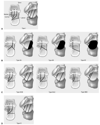 Fig. 8-42 Illustration of the Sanders computed tomography (CT) classification of calcaneal fractures involving the posterior facet. A: The widest undersurface of the posterior facet is divided by two lines (A and B) into three columns—medial, central, and lateral. Line C separates the medial column and sustentaculum. B: Type II—two-part fractures. IIA—fracture lateral or line A; Type IIB—fracture central or line B; Type IIC—fracture medial or line C. C: Type III—three-part posterior facet fractures with central depression. IIIAB—fracture lines lateral and central or A and B; Type IIIAC—fracture lines lateral and medial or A and C; Type IIIBC—fracture lines central and medial or B and C. D: Type IV—four-part or highly comminuted posterior facet fractures or lines A, B, and C. |
Fracture Classifications
Calcaneal fracture classifications have been modified over the years from the Rowe, Essex-Lopresti, Orthopaedic Trauma Association, and in recent years several classifications based upon CT findings, specifically related to the posterior facet. The Sanders classification is useful for correlating image features with prognosis and treatment approaches. With this method the coronal image with the widest undersurface of the posterior talar facet is divided by two lines (A and B) into three columns. The two lines separate the posterior calcaneal facet into three segments—medial, central, and lateral. A third line (C) separates the margin of the posterior facet from the sustentaculum resulting in four potential fragments. The lines are named A, B, and C moving from lateral to medial as the more medial the fracture the more difficult the reduction (see Fig. 8-42).
Almost all calcaneal fractures should be evaluated with CT to exclude articular involvement. Therefore, this classification has more application for imagers than some of the other fracture classifications.
Suggested Reading
Daftary A, Haims AH, Baumgaertner MR. Fractures of the calcaneus: A review with emphasis on CT. Radiographics 2005;25:1215–1226.
Fitzgibbons TC, McMullen ST, Mormino MA. Fractures and dislocation of the calcaneus. In: Bucholtz RW, Hechman JD, eds. Rockwood and Green’s fractures in adults, 5th ed. Philadelphia: Lippincott Williams & Wilkins; 2001:2133–2179.
Kay RM, Tang CW. Pediatric foot fractures: Evaluation and treatment. J Am Acad Orthop Surg. 2001;9:308–319.
Sanders R, Fortin P, DiPasquale T, et al Operative treatment of 120 displaced intra-articular calcaneal fractures: Results using a prognostic computed tomography scan classification. Clin Orthop. 1993;290:87–95.
Imaging of Calcaneal Fractures
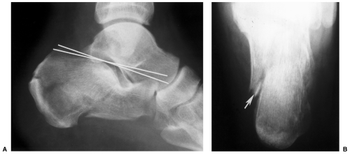 Fig. 8-43 Lateral (A) and axial (B) views of the calcaneus in a patient with a complex fracture and marked reduction in Bohler angle (lines). The axial view (B) demonstrates the fracture (arrow) and calcaneal widening. |
Radiographs should be obtained as the initial screening examination for suspected calcaneal fractures. Lateral and axial projections are obtained. The latter is useful to evaluate calcaneal width although the articulations may not always be identified (see Fig. 8-43). There are two key measurements that should be made routinely on the lateral radiograph. The Bohler angle (normal 25 to 40 degrees) (see Fig. 8-44) is a useful measurement for evaluating calcaneal height. The angle is formed by a line from the posterior superior calcaneal margin to the upper margin of the posterior calcaneal facet. A second line is drawn from the posterior superior margin of the facet
to the upper margin of the anterior calcaneal process. The crucial angle of Gissane (normal ∼100 degrees) (Fig. 8-44) is formed by lines along the posterior facet and anterior calcaneal process.
to the upper margin of the anterior calcaneal process. The crucial angle of Gissane (normal ∼100 degrees) (Fig. 8-44) is formed by lines along the posterior facet and anterior calcaneal process.
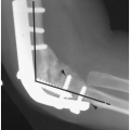
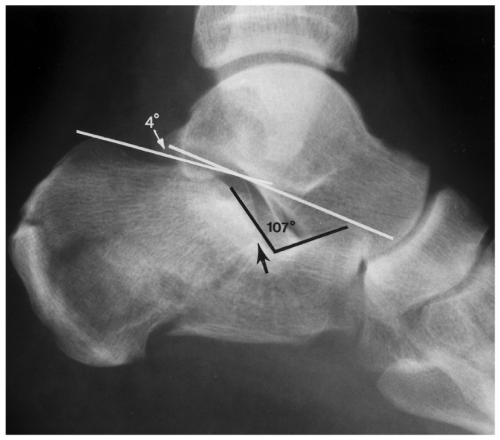 Fig. 8-44 Measurements on the lateral radiograph. Complex calcaneal fracture. The Bohler angle is formed by a line from the posterior superior calcaneal margin to the upper margin of the posterior calcaneal facet. The second line is from the margin of the facet to the superior margin of the anterior calcaneal process. The angle (white lines) is decreased to 4 degrees (normal 25 to 40 degrees). The crucial angle of Gissane is formed by lines along the posterior facet and anterior calcaneal process (black lines). The angle is increased to 107 degrees (normal ∼100 degrees). The fracture (arrow) enters the posterior facet. |
CT with reformatting in the coronal and sagittal planes is essential to classify the type of injury and plan appropriate management (see Fig. 8-45). Coronal and sagittal reformatted images are aligned from the axial images along the axis of the talus to best define the posterior facet. Three-dimensional reconstructions can also be obtained although they typically do not add significant new information.
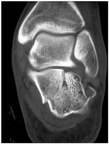 Fig. 8-45 Coronal computed tomographic (CT) image of the posterior facet demonstrating a single fracture line laterally (A) with displacement or Sanders type II fracture. |
MRI is useful for subtle osseous injuries, such as stress fractures, tubercle, or process fractures (see Fig. 8-46) and to evaluate the soft tissues to exclude peroneal tendon dislocation, tendon entrapment, and compartment syndrome.
Suggested Reading
Related posts:
Stay updated, free articles. Join our Telegram channel

Full access? Get Clinical Tree


