, Gila Perk2, Natesa G. Pandian3, Hans-Joachim Nesser4 and Itzhak Kronzon2
(1)
Department of Cardiology, Cardiocentro Ticino, Lugano, Switzerland
(2)
Non-Invasive Cardiology, Lenox Hill Hospital, New York, NY, USA
(3)
Tufts University School of Medicine, Boston, MA, USA
(4)
Department of Medicine Elisabethinen, Teaching Hospital, Linz, Austria
Abstract
Complex ablations procedure might greatly benefit of an imaging technique capable of showing the anatomical details of the ‘terrain’ where the ablation takes place, guiding in real time catheter movements and continuously monitoring the catheter-tissue contact points during the energy delivery. Because 3D TEE provides high-resolution 3D images of the anatomy of the posterior structures of the heart (i.e. left and right atrium), at least in theory, this technique may have the potential to become a new, anatomy-driven navigational guide for ablation procedures. In this chapter we illustrate, normal 3D TEE anatomy of right and left atrial structures involved in ablation procedures and their anatomical variants, and then discuss the strengths and limitations of the technique during catheter ablation for typical atrial flutter and atrial fibrillation.
Electronic supplementary material
The online version of this chapter (doi:10.1007/978-1-4471-4745-9_9) contains supplementary material, which is available to authorized users.
The past two decades have seen remarkable progress in catheter-based ablation of rhythm disorders. Originally, ablation therapy was used to treat relatively simple arrhythmias with a single, discrete target site, such as atrioventricular nodal reentry or tachycardia associated with Wolff-Parkinson-White syndrome. As experience in this field has grown and new and more sophisticated technological advancements have been introduced, ablation procedures have become available to address more and more complex arrhythmias.
The ability to perform complex ablations with high rates of success and low rates of complications requires a profound knowledge of cardiac anatomy. Understanding anatomy and correlating it with observed electrophysiologic phenomena may provide insight into the arrhythmia’s mechanisms, but at present, the primary value of detailed anatomic assessment of cardiac structures to be ablated is in the management of difficult ablations. Unexpected anatomic variants or barriers may cause difficulties in the manipulation of the catheter or in the catheter’s stability during the energy delivery, prolonging the procedural time or causing inadequate ablation with subsequent recurrence of arrhythmia. An imaging technique that can identify a priori any unusual anatomic variants of the target structures may allow the electrophysiologist to adapt the interventional strategies and equipment—in other words, to tailor the ablative approach.
During the procedure, a useful imaging technique should be able to assist in three ways: (1) showing in three dimensions the anatomic details of the “terrain” where the ablation will take place, (2) guiding in real time all catheter movements and positions relative to anatomic structures to which energy should be applied, and (3) continuously monitoring the catheter-tissue contact points during the energy delivery.
Three-dimensional transesophageal echocardiography (3D TEE) is a novel imaging technique that provides high-resolution 3D images of the anatomy of the posterior structures of the heart, with an unprecedented richness of anatomic details. Moreover, it has been shown to be capable of easily tracking catheter motion. Thus, at least in theory, 3D TEE may have the potential to become a new, anatomy-driven navigational guide for ablation procedures. However, though the use of 3D TEE during other percutaneous structural heart disease interventions is well established, this is not the case for ablation procedures. Currently, the role of 3D TEE has been systematically investigated only for ablation of typical atrial flutter and atrial fibrillation.
This chapter illustrates normal 3D TEE anatomy of right and left atrial structures involved in ablation procedures and their anatomic variants and then discusses the strengths and limitations of the technique during catheter ablation for typical atrial flutter and atrial fibrillation.
9.1 Normal 3D TEE Anatomy of the Right Atrium
Ablation of primarily right-sided atrial arrhythmias includes ablation of focal atrial tachycardia and atrial flutter. Sustained focal atrial tachycardia often originates from the junction between the crista terminalis (CT) and the pectinate muscles. Typical atrial flutter is a macro-reentrant circuit that uses the cavotricuspid isthmus (CVTI) as part of its circuit. The boundaries of this circuit consist of the tricuspid annulus, CT, inferior vena cava (IVC), Eustachian valve (EV) and ridge (ER), the ostium of the coronary sinus (CS), and probably the fossa ovalis. The CVTI provides a zone of “slow conduction” necessary for the reentry circuit. The following paragraphs describe the fine 3D TEE anatomy of these structures.
9.1.1 Crista Terminalis
The junction between the right atrial appendage (RAA) and the smooth posterior right atrial wall is marked externally by a fat-filled groove, the sulcus terminalis, which corresponds internally to a curved muscular band protruding into the right atrial cavity, which is named the crista terminalis (CT). The CT originates from the anteromedial wall of the right atrium, merges with the Bachmann bundle, continues along the anterior margin of the orifice of the superior vena cava (SVC), arches laterally, and descends towards the IVC, where it divides into thinner branches. An array of pectinate muscles arises from the CT and spreads throughout the RAA wall. The nonuniform architecture of the myofibers at the junction of the CT with the pectinate muscles may cause an anisotropy, which may be the substrate for reentry. Indeed, the CT is one of the most frequent sources of focal atrial arrhythmias; in patients without structural heart disease, two thirds of atrial arrhythmias originate along the long axis of the CT, with a gradient of frequency from the high to the low part of the crista.
Because the CT originates along the anterior border of the orifice of the SVC and runs towards the IVC, the volumetric data set derived from a two-dimensional (2D) TEE bicaval view should include this structure. It is difficult to obtain clear 3D TEE images of the CT, however, and it can be distinguished as a discrete muscular crest only when it is thick and prominent. Using 3D TEE perspectives that enhance shadowing between the margins of the CT and the surrounding atrial walls may help in differentiating the CT from the surrounding wall (Fig. 9.1).
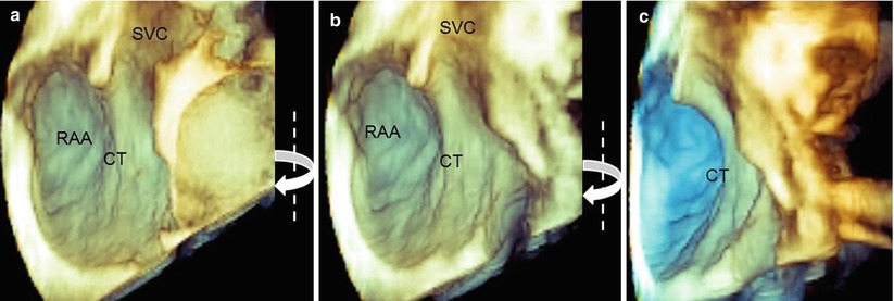
Fig. 9.1
(a) Three-dimensional TEE images showing a prominent crista terminalis (CT). (b, c) A clockwise rotation around the y-axis (curved arrows) enhances shadowing and allows differentiation of the CT from the surrounding atrial structures. RAA right atrial appendage, SVC superior vena cava
9.1.2 The Cavotricuspid Isthmus and Surrounding Structures
Anatomically, the CVTI is an endocardial region that is roughly quadrilateral; it is delineated anteriorly by the annular insertion of the septal and lateral tricuspid leaflets and posteriorly by the IVC border and the Eustachian valve and ridge. The lateral and medial borders are rather indistinctly defined by the terminal bundles of the CT and the lower border of the CS orifice, respectively. From an electrophysiologic standpoint, the CVTI may be divided into three regions: the septal isthmus between the CS ostium and the tricuspid annulus; the inferior isthmus between the orifice of the IVC and the posterior annulus of the tricuspid valve; and the inferolateral isthmus, which is the most lateral region bordered by the CT. The septal isthmus is shorter than the central isthmus, and the central isthmus is shorter than the inferolateral isthmus. Most commonly, the ablation line is traced along the inferior isthmus. This region presents the thinnest wall and includes the musculature and fibro-fatty tissue. Both these characteristics make the tissue less resistant to a complete transmural ablation.
The 3D TEE image of the CVTI can be obtained by focusing the volumetric pyramid on the aorta and enlarging the angle (or moving laterally) to include the entire right atrium. Once the entire pyramidal data set has been acquired, progressive cropping along the z-axis may disclose a panoramic view of the CVTI, including the inferolateral, the inferior, and the septal isthmus. In this plane, the short-axis view of the aorta and the sinuses can also be imaged (Fig. 9.2a). Because structures are opaque in 3D format, a prominent aortic root may partially cover the septal isthmus. In such a case, two maneuvers may be useful: further cropping along the same axis, which displays the septal isthmus by excluding the aorta (Fig. 9.2b), or a right-to-left rotation around the y-axis, which progressively reveals the CS ostium and the surface of the septal isthmus in an en face view (Fig. 9.3).
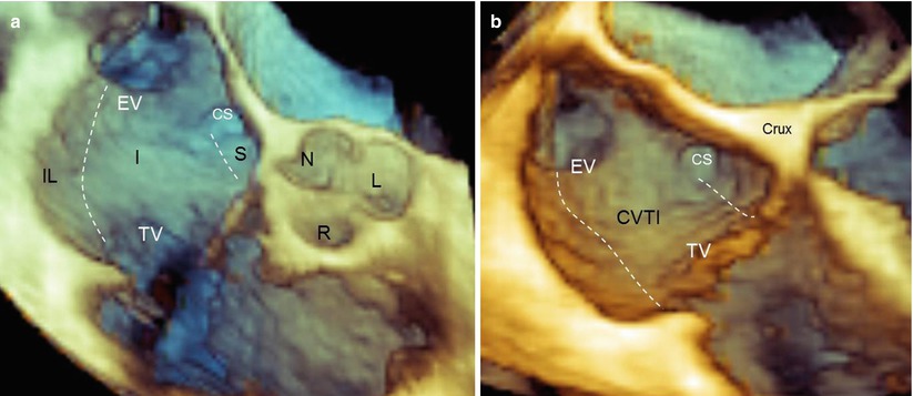
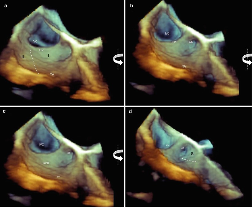
Fig. 9.2
(a) Three-dimensional TEE image of the entire region of the cavotricuspid isthmus (CVTI). The dotted lines mark the three of the CVTI: the inferolateral isthmus (IL), the inferior isthmus (I), and the septal isthmus (S). With a prominent aortic bulb, the septal isthmus may be partially covered by the aortic sinuses. (b) In that case, further cropping along the same axis may display a more posterior plane where the septal isthmus is no longer covered by the aorta. CS coronary sinus ostium, EV Eustachian valve, L left coronary sinus, N noncoronary sinus, R right coronary sinus
Fig. 9.3
(a) Three-dimensional TEE images of the cavotricuspid isthmus (CVTI). The borders of the inferolateral (IF) and inferior (I) isthmuses are traced (dotted lines), but the coronary sinus (CS) and the septal isthmus (the surface of the CVTI that is bordered by a line traced from the inferior border of the coronary sinus orifice to the hinge line of the tricuspid valve) are not visible. (b–d) A counterclockwise rotation around the y-axis (curved arrows) progressively shows the coronary sinus orifice and the surface of the septal isthmus (S) in an en face view. EV Eustachian valve, IVC inferior vena cava, TV tricuspid valve
9.1.3 The Eustachian Valve and Ridge
The posterior border of the CVTI is defined by the Eustachian valve (EV). This flap of tissue guards the junction of the IVC and the right atrium. In fetal life, the EV directs the flow of oxygen-rich blood from the IVC into the left atrium through an open foramen ovale, preventing blood from flowing into the right ventricle. Following birth, the EV persists as a remnant of the embryologic valve, without a specific function. This flap of fibrous or fibromuscular tissue continues medially into the Eustachian ridge (ER), a prominence of tissue between the fossa ovalis and CS orifice. The EV may vary from a thin, almost invisible flap to a large, crescent-shaped fibromuscular tissue. In about 2 % of patients, the EV has a reticulum of lacelike strands of varying sizes, called the Chiari network.
Three-dimensional TEE is an ideal tool for imaging the EV. The valve can be visualized from several perspectives. Notably, when it is seen from the right atrial perspective, the EV is easily recognizable; its triangular shape is well delineated from the surrounding atrial wall. Conversely, when it is observed from a “caval” perspective, the valve forms a continuous surface with that of the IVC (Fig. 9.4).
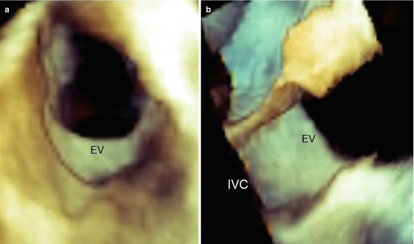
Fig. 9.4
Three-dimensional TEE images of the Eustachian valve (EV) seen from the right atrial perspective (a) and the caval (IVC) perspective (b). From the atrial perspective, the EV is easily recognizable, but from caval perspective, it forms a continuous sheath with the caval wall
When the EV is thin, fine-tuning of the gain may be necessary to display the entire surface of the valve without dropout artifacts. Nevertheless, these artifacts sometimes cannot be avoided (Fig. 9.5).
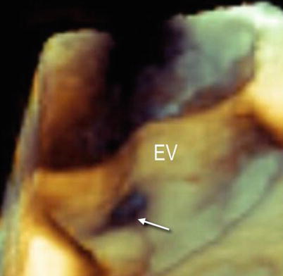
Fig. 9.5
Three-dimensional TEE image of a large and thin Eustachian valve (EV). Despite fine-tuning, dropout artifacts (arrow) are still present
Anatomic details of the EV and ER may be discovered with magnified images and unusual perspectives. Figure 9.6a shows the EV from a caval perspective. Right-to-left rotation of the image around the y-axis progressively reveals the EV and the ER from a lateral perspective and eventually an atrial perspective. In particular, the ER can be distinguished from the EV as a prominence between the fossa ovalis and the CS.
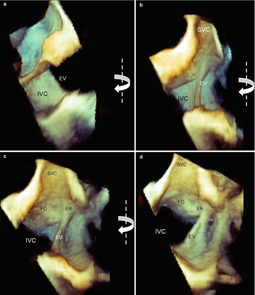
Fig. 9.6
Three-dimensional TEE magnified images of the Eustachian valve (EV) and Eustachian ridge (ER). From a caval perspective (a), the surface of the EV is progressively visualized with right-to-left rotation (curved arrows) from lateral perspectives (b, c) and an atrial perspective (d). The ER can be easily imaged between the fossa ovalis (FO) and the coronary sinus (CS). IVC inferior vena cava, SVC superior vena cava
The orifice of the CS is guarded by a thin, crescent-shaped flap of tissue called the Thebesian valve. The shape of this valve varies from a clear, crescentic flap (with or without fenestrations) to a thin, strand-like, nearly invisible structure. An extensive, imperforate flap covering the orifice to some extent can be seen by 3D TEE, in both an en face and longitudinal view (Fig. 9.7).
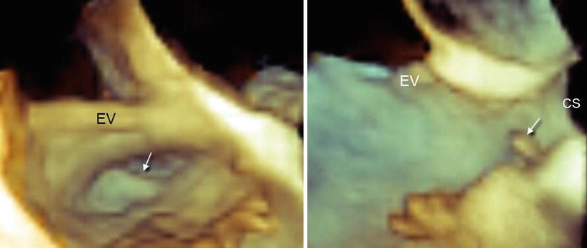
Fig. 9.7
Thebesian valve (arrow) in en face view (a) and longitudinal view (b). CS coronary sinus, EV Eustachian valve
9.1.4 Using 3D TEE to Discover Anatomic Variants Associated with Difficult Ablation
Several anatomic variants may create difficulties in an ablation procedure. This unusual anatomy can be discovered by 3D TEE.
9.1.4.1 CVTI Diastolic Length or Verticality
A longer diastolic isthmus or an angulation between the IVC and CVTI close to 90° is associated with difficult CVTI ablation. Appropriate 3D TEE perspectives may provide such quantitative data. Measurements of CVTI length can be made in both multiplanar and 3D format (Fig. 9.8).
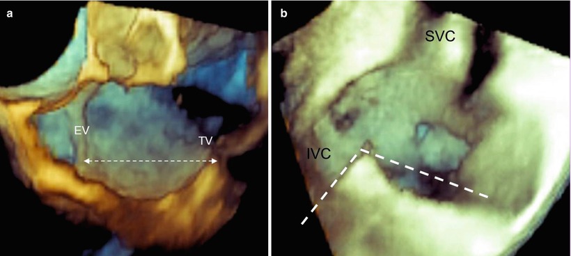
Fig. 9.8
(a) Length of the cavotricuspid isthmus (CVTI). (b) The angle between the inferior vena cava (IVC) and CVTI measured in volume-rendering format. SVC superior vena cava
9.1.4.2 Prominent EV
A very prominent and rigid EV may make catheter manipulations difficult, acting like a fulcrum and making the catheter’s movements unpredictable and counterintuitive. Moreover, its presence may prevent firm catheter contact with the CVTI (Fig. 9.9). In such a case, a long guiding sheath may be of assistance during the procedure.
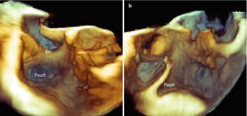
Fig. 9.9
A large and thick Eustachian valve (EV), which may cause difficulty in the catheter’s manipulation, as seen in en face view (a) and a lateral view (b). A deep pouch can also be seen
9.1.4.3 Sub-Eustachian Pouch
Related posts:


Stay updated, free articles. Join our Telegram channel

Full access? Get Clinical Tree


