and Horia Ples2
(1)
Department of Computed Tomography, SCM Neuromed, Timisoara, Romania
(2)
Department of Neurosurgery, University of Medicine and Pharmacy “Victor Babes”, Timisoara, Romania
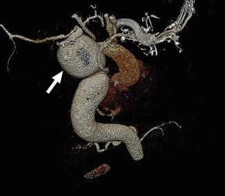
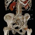
3.1 Aneurysm of the Aorta Ascendens
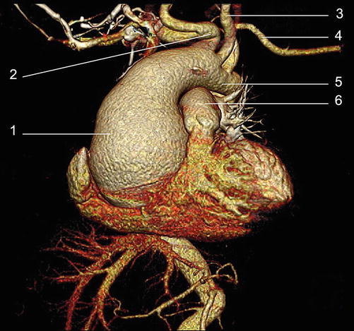
Fig. 3.1
3D VRT colour reconstruction, after removal of the thoracic cage
1. Aorta ascendens. Aneurysmal dilatation
2. Truncus brachiocephalicus
3. A. carotis communis sinistra
4. A. subclavia sinistra
5. Arcus aortae
6. Truncus a. pulmonalis
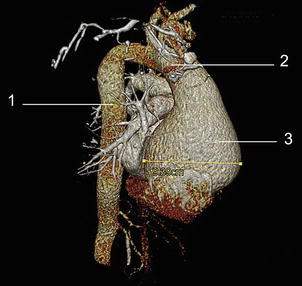
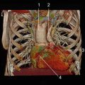
Fig. 3.2
3D VRT colour reconstruction, after removal of the thoracic cage
1. Aorta descendens thoracica
2. Arcus aortae
3. Aneurysm
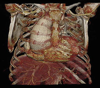
Fig. 3.3
3D VRT colour reconstruction, anterior plane
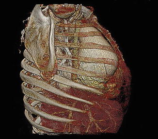
Fig. 3.4
3D VRT colour reconstruction, right sagittal plane
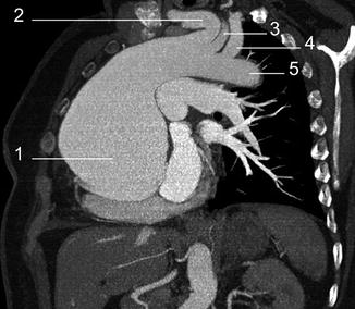
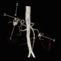
Fig. 3.5
3D MIP reconstruction, coronal plane
1. Aneurysm
2. Truncus brachiocephalicus
3. A. carotis communis sinistra
4. A. subclavia sinistra
5. A. aorta descendens
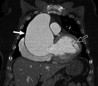
Fig. 3.6
3D MIP reconstruction, coronal plane
Full arrow = aneurysm
Arrow with contour = ventriculus sinister
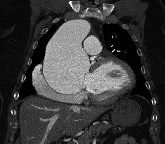
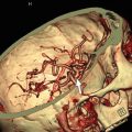
Fig. 3.7
3D MIP reconstruction, coronal plane
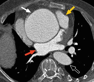
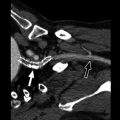
Fig. 3.8
3D MIP reconstruction, axial plane
Full arrow = aneurysm
Arrow with contour = aorta descendens
Yellow arrow = ventriculus sinister
Red arrow = atrium sinister
3.2 Supravalvular Aortic Stenosis
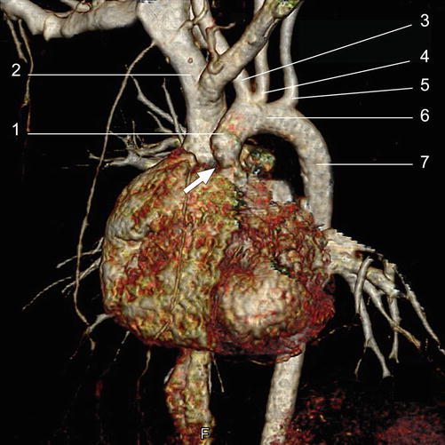
Fig. 3.9
3D VRT colour reconstruction, after removal of the bone structure
1. A. ascendens
2. V. brachiocephalica dextra
3. Truncus brachiocephalicus
4. A. carotis communis sinistra
5. A. subclavia sinistra
6. Arcus aortae
7. Aorta descendens
The full arrow indicates stenotic area
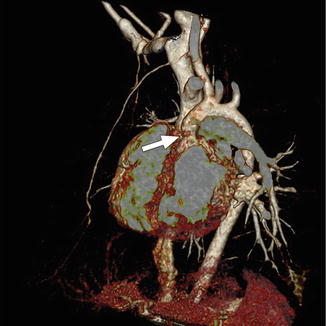
Fig. 3.10
3D VRT colour reconstruction, after removal of the bone structure, oblique anterior plane
Full arrow = supravalvular stenotic area
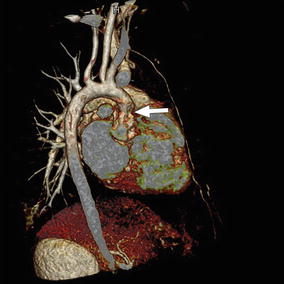
Fig. 3.11
3D VRT colour reconstruction, after removal of the bone structure, posterior oblique plane
Full arrow = supravalvular stenotic area
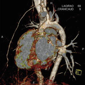
Fig. 3.12
3D VRT colour reconstruction, enlarged image
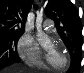
Fig. 3.13
3D MIP reconstruction, tract of ejection ventriculus sinister
Full arrow = supravalvular stenotic area
Arrow with contour = tract of ejection ventriculus sinister
Tip of the arrow = ventriculus sinister
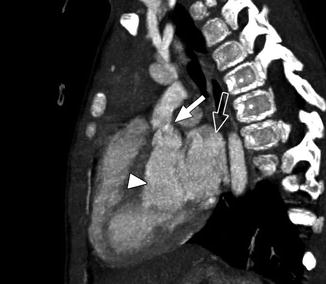
Fig. 3.14
3D MIP reconstruction
Full arrow = supravalvular stenotic area
Arrow with contour = atrium sinistrum
Tip of the arrow = tract of ejection ventriculus sinister
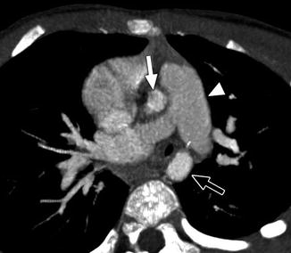
Fig. 3.15
3D MIP reconstruction, axial plane
Full arrow = aorta ascendens
Arrow with contour = aorta descendens
Tip of the arrow = truncus a. pulmonalis
3.3 Aneurysm of the Aorta Ascendens: Isthmic Stenosis
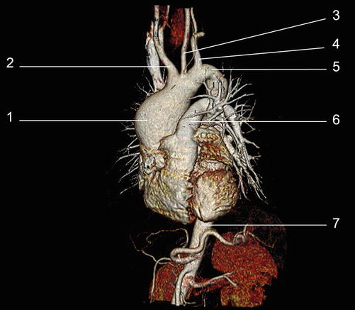
Fig. 3.16
3D VRT colour reconstruction, after removal of the bone structure, left anterior oblique plane
1. Aorta ascendens
2. Truncus brachiocephalicus
3. A. carotis communis sinistra
4. A. subclavia sinistra
5. Area of isthmic stenosis
6. Truncus a. pulmonalis
7. Aorta descendens
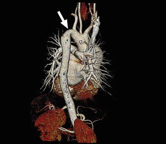
Fig. 3.17
3D VRT colour reconstruction, after removal of the bone structure, posterior oblique plane
Full arrow = area of isthmic stenosis
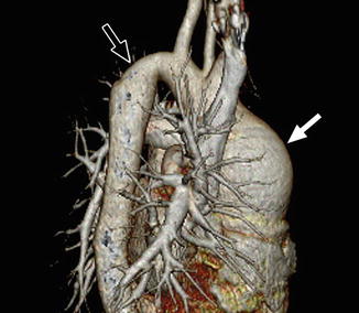
Fig. 3.18
3D VRT colour reconstruction, after removal of the bone structure, posterior oblique plane
Full arrow = dilated aneurysm at the aorta ascendens
Arrow with contour = area of isthmic stenosis
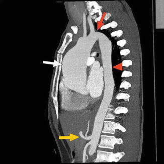
Fig. 3.19
3D MIP reconstruction, sagital plane
Full arrow = aneurysm of the aorta ascendens
Full red arrow = isthmic stenotic area
At the tip of the red arrow = aorta thoracica
Yellow arrow = truncus coeliacus and arteria mesenterica superior
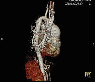
Fig. 3.20
3D VRT colour reconstruction, right sagital plane
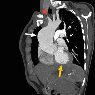
Fig. 3.21
3D MIP reconstruction, sagital plane
Full arrow = aneurysm of the aorta ascendens
Yellow arrow = ventriculus sinister
At the tip of the red arrow = emerging vessels from the arcus aortae
3.4 Aneurysm of the Arcus Aortae
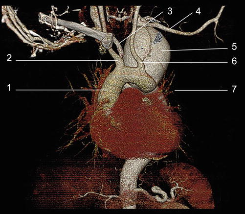
Fig. 3.22
3D VRT colour reconstruction, after removal of the bone structure, anterior view
1. Aorta ascendens
2. A. carotis communis dextra
3. A. subclavia dextra
4. A. subclavia sinistra
5. Aneurysm of arcus aortae
6. A. carotis communis sinistra
7. Aorta descendens
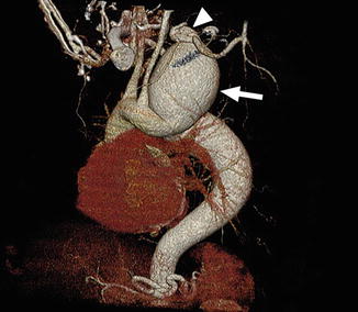
Fig. 3.23
3D VRT colour reconstruction, after removal of the bone structure, left anterior oblique view
Full arrow = aneurysm of the arcus aortae
At the tip of the arrow = abnormal emergence of the a. subclavia sinister from the level of the superior pole of the aneurysm
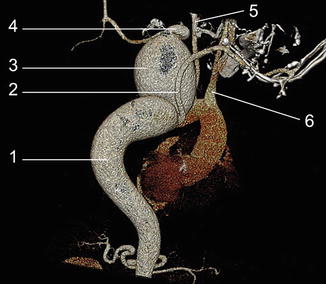
Fig. 3.24
3D VRT colour reconstruction, after removal of the bone structure, posterior view
1. Aorta thoracica
2. A. subclavia dextra
3. Aneurysm
4. A. subclavia sinistra
5. A. carotis communis sinistra
6. A. carotis communis dextra
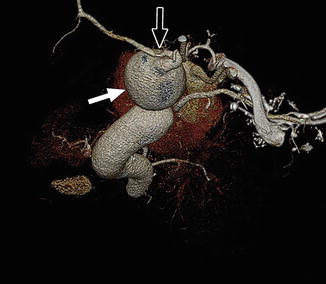
Fig. 3.25
3D VRT colour reconstruction, after removal of the bone structure, posterior cranial view
Full arrow = aneurysm
Arrow with contour = emergence of a. subclavia sinistra from the cranial extremity of the aneurysm
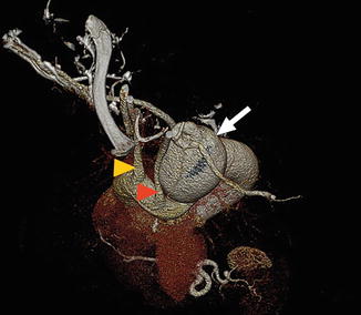
Fig. 3.26
3D VRT colour reconstruction, after removal of the bone structure, anterior cranial view
Full arrow = aneurysm
Tip of the yellow arrow = a. carotis communis dextra
Tip of the red arrow = a. carotis communis sinistra