
Thoracic Instrumentation: Stereotactic Navigation for Placement of Pedicle Screws in the Thoracic Spine
Application of transpedicular screws for posterior fixation in the treatment of spinal instability has undergone continuous evolution and refinement in technique since King attempted the first transfacet screw in 1944.1 Even before the Food and Drug Administration upgraded them from a Class III to a Class II device in July 1998, pedicle screws in the lumbar spine were considered by many to be the best and most rigid form of posterior spinal fixation. Due to the smaller size and more complex three-dimensional morphology of the thoracic pedicle, transpedicular screw placement in the thoracic spine can be extremely challenging and has not been widely advocated. Anatomic studies have demonstrated a wide degree of variability of pedicular diameter, shape, and angle (Fig. 21–1). Given the proximity of the thoracic pleura, nerve roots, and spinal cord itself, serious morbidity can accompany a less than perfectly placed thoracic pedicle screw.
 Anatomic Background
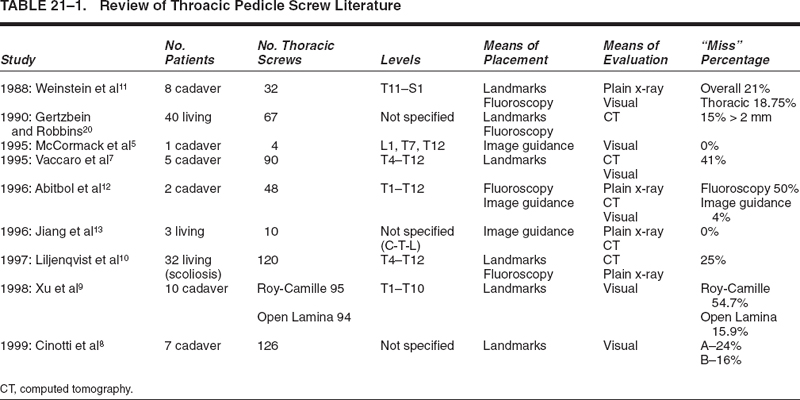
Over the past several years, a wealth of data has accumulated regarding the anatomy of the thoracic pedicle.2–7 Utilizing this data, a variety of techniques have been developed in an effort to decrease the complications associated with thoracic pedicle screw placement.8,9 In contrast to the lumbar spine, there is considerable variation among thoracic vertebrae, in both the relationship of the transverse process to the axis of the pedicle and the angle of the pedicle to the vertebral body.5 Due to the variability of these individual parameters, freehand placement of thoracic pedicle screws using anatomic landmarks may be imprecise and may thus lead to errors in screw placement. Clinical and cadaveric studies have shown that 15 to 50% of thoracic screws violate the pedicular cortex when placed using anatomic landmarks and fluoroscopic techniques.8–11 Analysis of pedicular cortex violations has included direct visualization (cadaveric studies), plain x-ray, and thin-cut computed tomographic (CT) scans (Table 21–1).
Image-guided stereotaxy provides three-dimensional, intraoperative guidance, which is well suited for thoracic pedicle screw size and trajectory. Recently, cadaveric studies have investigated the accuracy of this technology with extremely encouraging results.12–14 In a recent analysis at our institution, we designed a retrospective study to assess the clinical accuracy and safety of thoracic pedicle screw placement utilizing intraoperative navigational techniques by several surgeons of varying experience and skill.
 Accuracy of Stereotactic Thoracic Pedicle Screw Placement
Since 1996, 266 thoracic pedicle screws, in 65 patients, were placed using image-guided techniques. All screws were placed by one of four surgeons with a range of experience in posterior spinal fixation and intraoperative navigation. Screw diameter ranged from 4.5 mm in the mid and upper thoracic spine to 6.5 mm in the lower thoracic spine. Screw length varied from 25 to 55 mm and was predetermined by measurement on the stereotactic planning station. The StealthStation (Medtronic SNT, Louisville, CO) stereotactic image-guidance computer platform was utilized in all instances of screw placement. Operating system updates occurred on a regular basis, from version 2.3 to 3.0 from 1998 to 2000. Registration methods were “paired-point” in 1998 to mid-1999 and “paired-point with surface merge” from mid-1999 to the present. Indications for thoracic pedicle screw fixation included trauma, tumor, instability, kyphosis, and scoliosis.
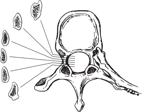
FIGURE 21–1. This schematic representation depicts the variable coronal anatomy of the thoracic pedicle going from anterior to posterior.
Medical charts were reviewed, and patient demographics including diagnosis, operative procedure, and postoperative complications were recorded. All patients without an existing appropriate postoperative CT scan were contacted and asked to participate in the study and return for the protocol CT scan. Postoperative thin-cut CT scans (3 mm contiguous, nonoverlapping images) were obtained in 52 patients, and an impartial neuroradiologist evaluated all 224 screws with a standardized report form. Screws that violated the pedicular cortex were then graded with respect to degree of cortical perforation and angle of trajectory using a modified grading system (Fig. 21–2). Screws that replaced the cortex without extending beyond the pedicular cortical margin were considered Grade I screws. A Grade II violation was defined as a screw that extended less than 2 mm beyond the pedicular cortex. Screws that extended greater than 2 mm beyond the pedicular margin were considered Grade III violations (Fig. 21–3). Grade II and Grade III screws were considered true cortical violations. Grade III violations were further divided into “intentional lateral screw entry through the costovertebral joint” (scaphoid pedicles) and true “anatomically significant errors.”
Review of the clinical charts revealed no incidence of postoperative neurological, cardiovascular, or pulmonary injury. Pedicle screws were placed in all levels of the thoracic spine (T1–T12) (Table 21–2). Of the 224 screws evaluated, there were 12 Grade I screws and 19 screws with Grade II or Grade III cortical violations (8.5%). Of the 19 cortical violations there were 11 Grade II and 8 Grade III screws. The most common trajectory for these violations was lateral to the pedicle. There were two inferior violations, three medial violations, and only one superior violation (Table 21–3A). Analysis using Chi-square and one-sided Fisher’s exact tests revealed a trend (P = 0.0735) involving higher rates of cortical perforation in the midthoracic spine (T4–T8 = 16.7%) when compared with the upper thoracic (T1–T4 = 8.8%) and lower thoracic (T9–TI2 = 5.6%) regions (Table 21–3B). After controlling for surgeon difference and accounting for correlation of multiple screws placed within the same patient, a logistic regression analysis demonstrated a statistically significant difference in the rate of pedicular violation in the midthoracic spine [P = 0.0072, odds ratio (OR) = 5.66, and 95% confidence interval = 1.6–2.0 from T4 to T9]. Thoracic levels with the highest rates of cortical violation in our series included T4 (P = 0.0005, OR = 31.3), followed by T8 (P = 0.0049, OR = 21.9) and T2 (P = 0.0173, OR = 18.5).
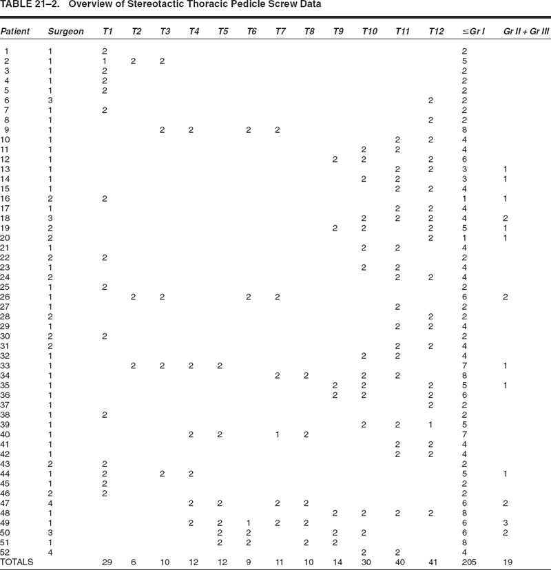
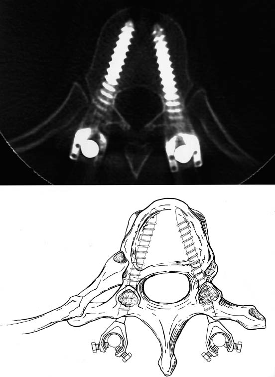
FIGURE 21–2. This illustration and photoradiograph depict the desired outcome after proper screw positioning.
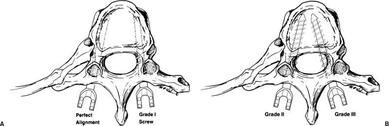
FIGURE 21–3. (A). This figure demonstrates thoracic pedicle screws that were considered to be in acceptable position. Grade I screws were not counted as violations because they replaced the pedicular cortex without extending beyond it. (B). Grade II and Grade III medial cortical violations are demonstrated in this figure. Grade II violations were defined as screws that extended ≤ 2 mm beyond the pedicular cortex, whereas Grade III violations were defined as screws found to be > 2 mm outside of the cortical margin.
Related posts:
 Intraoperative Image Update by Interface with Ultrasound
Stay updated, free articles. Join our Telegram channel

Full access? Get Clinical Tree


