Thoracic, Pulmonary Arteries, and Peripheral Vascular Disorders
Michael J. Miller Jr.
Tony P. Smith
Introduction to Vascular Radiology
The walls of both arteries and veins are made up of three layers from the inside out: the intima, the media, and the adventitia. The intima is a single cell layer thick and has the primary function of interacting with the flowing blood, in particular, preventing thrombosis. It is by far the most chemically active layer. The media is composed for the most part of smooth muscle, greater of course in large muscular arteries and less in smaller arteries and veins. Smooth muscle cells can contract to augment normal hemodynamic function and to respond to stress, such as with vasoconstriction (vasospasm). The adventitia is a layer of supportive connective tissue of varying thickness, which surrounds and supports the media.
The anatomical structure of the vessel wall is actually simple, but its physiologic and pathologic function is very complex and for the most part poorly understood. A wide variety of disease processes can affect the vessel wall, particularly the arterial wall. These diseases include inflammation (vasculitis), fibromuscular disease (FMD), connective tissue disease, trauma, and of course degeneration (atherosclerosis) to name a few. Although we often do not understand the exact pathophysiology underlying a vessel’s reaction to a particular disease process in a particular individual, the arterial wall and vessel itself has only a limited number of radiographic manifestations. When the vessel wall is “attacked,” it can weaken and dilate, producing an aneurysm or can even rupture causing extravasation, pseudoaneurysm formation, or arteriovenous fistulas. It can thicken by either growth of the vessel layers (intimal hyperplasia for example) or the deposition of material, such as an atherosclerotic plaque, causing the vessel to narrow producing a stenosis or even occlusion. The vessel may lose its ability to prevent coagulation resulting in thrombosis. As yet unknown genetic factors may induce the proliferation of vessels resulting in arteriovenous malformations (AVMs), or vessels may be induced to grow and proliferate by “acquired” factors such as within a tumor. If one keeps in mind the vessel wall, in particular the arterial wall, much of what is seen angiographically is more easily understood.
Angiographic Suite. Most angiographic suites have two major types of equipment, patient monitoring devices and radiographic equipment. Patient monitoring devices are essential to patient care during the procedure especially for conscious sedation, and there are usually one or more channels for pressure measurements. Radiographic equipment today is based on a C-arm design that allows complex angulation and is equipped for digital acquisition only. C-arm configuration allows one to set the angle for imaging; therefore the technologist no longer has to place the patient based on landmarks into the “named” positions. One is also able to acquire images at a rapid rate for long periods of time and allows for special imaging such as bolus chasing for leg angiography and rotational angiography which provides three-dimensional image viewing.
Tools. There are a number of catheters used in interventional radiology that can be loosely divided into five types: diagnostic angiographic catheters, microcatheters, drainage catheters, balloon catheters, and central venous catheters.
There are a host of properties considered in manufacturing, buying, and using diagnostic angiographic catheters; these include size (the smaller the better for access but size limits the lumen), shape, radiopacity, torquability, and softness of the distal tip. Larger lumen diagnostic catheters are available (guiding catheters) for placement of microcatheters and angioplasty balloons in a coaxial fashion.
Microcatheters are 3 French or less in size and are designed for very distal catheterization. These catheters are placed over 0.010″ to 0.018″ guide wires. Originally developed for the neurointerventional arena, they have become very helpful for peripheral intervention to superselect small vessels for embolization or infusion (such as chemotherapy). These catheters have a distal platinum marker but are otherwise not very radiopaque.
Drainage catheters are used frequently in interventional radiology for drainage of fluid collections (abscess, pleural fluid,
ascites, lymphoceles) and visceral structures including nephrostomy, biliary, gallbladder, and GI tract. The same basic catheters are used for drainage in all such sites. Characteristics of drainage catheters include caliber, sidehole diameter, biocompatibility, radiopacity, and softness shape/retention property. Catheter shape is usually based on the size of the fluid collection for drainage and the retention property. The most common retention device for pigtail catheters is the retention suture. Straight catheter retention devices include the mushroom tip or inflatable balloon.
ascites, lymphoceles) and visceral structures including nephrostomy, biliary, gallbladder, and GI tract. The same basic catheters are used for drainage in all such sites. Characteristics of drainage catheters include caliber, sidehole diameter, biocompatibility, radiopacity, and softness shape/retention property. Catheter shape is usually based on the size of the fluid collection for drainage and the retention property. The most common retention device for pigtail catheters is the retention suture. Straight catheter retention devices include the mushroom tip or inflatable balloon.
Angioplasty balloons either can be very soft and pliable such as occlusion balloons or Fogarty balloons to clear thrombosis or can be more rigid and used for dilations (angioplasty). Balloons for dilation can be divided into two main categories regarding the size of guide wire over which they are placed: 0.018 inch (or even smaller including 0.014′) and 0.035 inch. The smaller guide wire lumen obviously allows the balloon to be lower profile. These are the balloons used for coronary angioplasty, but have become popular recently in peripheral and neuroradiologic interventional procedures. The smaller based systems do not have the guide wire support of the larger systems and the balloons cannot be constructed in very large diameters. Many peripheral interventions are performed with 0.035″-based balloon systems. There is an array of balloons in a variety of sizes. Large balloons require large access sites (introducer sheaths) especially for removal after inflation as they do not “re-wrap” very well. An important concept to understand for angioplasty balloons is compliance. Once the balloon reaches its manufacturer’s stated size, it can be very firm (noncompliant) or it can “grow” a little with increasing inflation pressure (compliant). There are advantages to each. Noncompliant balloons are useful with very difficult/hard lesions which can be dilated without overdilating the adjacent normal caliber artery. Compliant balloons offer the option that one can “size” the balloon a little larger than its stated size by increasing the atmospheric pressure during dilation. This allows one to more fine-tune the angioplasty. However, compliant balloons are often composed of a softer material which is more prone to rupture if very high pressures are desired.
Central venous access can be differentiated into temporary, tunneled, and implantable. Temporary access include traditional central lines (multilumen central venous lines, Swan–Ganz catheters), which are placed for temporary care and monitoring. A special one of these is the peripherally inserted central catheter, which is placed via a peripheral arm vein coursing into the central veins for access up to 6 weeks. Tunneled access is placed using subcutaneous tunnels from the venous access to the skin exit site. Most catheters have a retaining fabric (usually Dacron) cuff to prevent dislodgment by the in-growth of connective tissue. Choice of the type of device depends on its clinical use based on a variety of factors including number of lumens needed, frequency of use, type of use, length of use, device location, and individual patient factors. The two primary categories of tunneled access are large bore catheters which are used for high-flow demands such as hemodialysis or plasmapheresis or small bore catheters used for chemotherapy, IV antibiotic administration, or total parenteral nutrition. They are less expensive and less invasive to place than completely implanted ports but tend to have higher infection rates and are less cosmetically desirable. Implantable access is placed completely under the skin within a subcutaneous pocket. Implanted ports contain catheters that are tunneled a short distance from the venous access where the port (reservoir) device is implanted in a subcutaneous pocket. These are typically indicated in patients requiring chemotherapy or other long-term requirements for IV medical therapy. These are more resistant to infection; however they are more difficult to remove in the setting of catheter-related infection.
Most guide wires for standard angiography and interventional procedures fall into two categories based on their construction: spring guide wires which are constructed of stainless steel wire tightly wound on itself to form a spring and nitinol guide wires constructed of a nickel titanium alloy and an organic coating to which is bound a hydrophilic coating. This coating absorbs water and becomes very slippery. Guide wires range in size from 0.010 inches to 0.038 inches. Wires differ in character based upon the requirements needed during the procedure including support, torquability, profile, and device compatibility.
Stents can be divided into three major categories of bare metal stents, drug eluting stents, and stent grafts. Bare metal stents include balloon- and self-expanding delivery systems. Balloon-expandable stents are composed for the most part of stainless steel which offers the advantage of improved visualization and precision during deployment. The limitations include profile restrictions based upon their delivery balloon and flexibility in tortuous vessels. Self-expanding stents are composed of various metal combinations. They are constructed of either stainless steel or nitinol alloys. Self-expanding stents have the advantage of being quite flexible and lower in profile compared with balloon-expandable stents and can be constructed in quite large diameters. Their limitations include an increased difficulty to place precisely due to foreshortening upon stent opening. This problem has been lessened somewhat with the nitinol varieties. Drug eluting stents are stents that are coated with medications which are delivered locally to elicit a pharmacologic response. Most are used to prevent intimal hyperplasia which diminishes the lumen diameter. These are primarily used in coronary interventions but are starting to move toward utilization in peripheral interventions. Stent grafts are balloon- and self-expanding fabric covered stents which exclude the vessel wall, aneurysm, or arterial injury site. The fabric is most often polytetrafluoroethylene (PTFE). Smaller varieties are used for the peripheral circulation and larger varieties are used for the aorta. In their current form, peripheral stent grafts require relatively large introducer sheaths (minimum of 7 French and can be up to 12 F). Ones for the aorta require very large introducers (up to 30 French) requiring surgical access to the arterial entry site (usually common femoral artery).
Embolic agents can be easily divided into proximal or distal based upon their relationship with the catheter used to deliver the embolic. Other characteristics to consider with the agent are the desired location for occlusion, the permanence of occlusion, and radiopacity of the agent. Proximal agents occlude the vessel immediately adjacent to the delivery catheter. Plugs, coils, and microcoils are all considered to be proximal agents. Even in the example of super selective embolization for lower GI bleeding, the branch supplying the area of bleeding into the colon is selected with a microcatheter, and a microcoil is placed just beyond the delivery system for occlusion of the vessel. Distal agents are smaller and flow, for example, into the nidus of an AVM or into a tumor bed for occlusion of small vessels. Chiefly, these agents are particles and liquids. A temporary agent is absorbed by the body and is principally represented by gelatin sponge. However, recanalization around an agent should also be considered temporary as can occur with nonspherical polyvinyl alcohol particles. The major available embolic agents are outlined in Table 23.1.
Medications. A number of medications are used in the interventional suite for conscious sedation. Probably the two most common are fentanyl (Sublimaze®: 25 to 100 μg bolus, 25 to 75 μg maintenance intravenously) and midazolam (Versed®: 0.5 to 2 mg bolus, 1 mg maintenance). If one is to administer these medications, it is essential that the reversal agents are understood. Fentanyl is reversed with naloxone (Narcan®: 0.4 to 2 mg IV). Midazolam is reversed with flumazenil
(Romazicon®: 0.2 mg IV over 15 seconds, with additional doses as required).
(Romazicon®: 0.2 mg IV over 15 seconds, with additional doses as required).
Table 23.1 Summary of Embolization Agents | ||||||||||||||||||||||||||||||||||||||||||||||||||
|---|---|---|---|---|---|---|---|---|---|---|---|---|---|---|---|---|---|---|---|---|---|---|---|---|---|---|---|---|---|---|---|---|---|---|---|---|---|---|---|---|---|---|---|---|---|---|---|---|---|---|
| ||||||||||||||||||||||||||||||||||||||||||||||||||
Antibiotic prophylaxis for vascular and interventional radiology is somewhat controversial. Most however suggest administration at least for contaminated (the presence of inflammation consistent with infection but no gross pus) or dirty (infected purulent site or infected GI or GU site) procedures. Many also give antibiotic prophylactically prior to central venous catheter placement.
Intraarterial pharmacoangiography consists of either vasodilators or vasoconstrictors. Vasodilators used to treat vasospasm whose etiology is either iatrogenic (catheter induced) or from other causes (trauma, medications, etc.). There are two vasodilators commonly used in vascular radiology: nitroglycerine (given intra-arterially in 100 μg doses) and papaverine (given intra-arterially in 25 to 100 mg doses). The only vasoconstrictor used with any frequency in vascular radiology is pitressin (Vasopressin®) that was historically given intra-arterially for transcatheter therapy of lower GI bleeding which has been mostly supplanted by embolization (see GI bleeding). Antithrombotic agents fall into two broad categories, anticoagulants and antiplatelets. Anticoagulants are pharmacologic agents that inhibit thrombin generation in vivo and are usually heparin intravenously and warfarin (Coumadin®) orally. These two anticoagulants have been the main stays of antithrombotic therapy for years. Newer anticoagulants such as direct thrombin inhibitors (bivalirudin, hirudin, argatroban) might offer significant advantages over heparin, but further studies are needed to demonstrate their safety and effectiveness.
Antiplatelet agents are either oral or IV. Oral antiplatelet medications include aspirin (either 81 mg or 325 mg) and the thienopyridines, which include ticlopidine (Ticlid®: 250 mg) and clopidogrel (Plavix®: 75 mg). IV antiplatelet agents consist of the glycoprotein IIb/IIIa antagonists, which are the “big gun” antiplatelet agents. The best know of these is abciximab (Reopro®). Antiplatelet agents have demonstrated clinical benefits in coronary interventions particularly following stent placement. Very little data exist regarding the use of these agents for peripheral interventions. They are however used in selected situations to decrease thrombus formation.
Thrombolytic agents are those that actually lyze or dissolve the existing thrombus, and the more commonly used agents are summarized in Table 23.2. In interventional radiology, thrombolytic agents are most often administered via a catheter directly into the thrombus located in the arterial or venous system. Catheter-directed thrombolysis is used to treat native arterial or bypass graft thrombosis, embolic occlusions, thrombosed hemodialysis access shunts, and deep venous thrombosis. The advantage of direct infusion (over empirical IV administration) is faster recanalization with a lesser dose of thrombolytic agent. Remember, despite this lessened dose, these medications dissolve thrombus anywhere in the body so the major contraindication is a known reason to hemorrhage (such as recent surgery, trauma, CNS lesion such as a recent stroke or tumor, etc.), and the major complication of thrombolytic therapy is likewise hemorrhage. Catheter-based infusion of a thrombolytic agent is an effective and well-established method of restoring blood flow in acute and subacute thrombotic occlusion. Once blood flow is reestablished, an underlying “culprit” lesion such as a stenosis is often found. This lesion, responsible for precipitating thrombosis, must be treated. This can often be achieved with percutaneous techniques such as angioplasty or stent placement. Surgical revascularization may also be indicated depending on the nature of the underlying problem. Occasionally, no culprit lesion is uncovered. Thrombosis in these cases may be related to hypercoagulability, hypotension, or external compression of the vessel or graft.
Table 23.2 Commonly Used Thrombolytic Agents | |||||||||||||||||||||||||
|---|---|---|---|---|---|---|---|---|---|---|---|---|---|---|---|---|---|---|---|---|---|---|---|---|---|
|
Thoracic Aortography
Anatomy. The thoracic aorta extends from the aortic valve to the diaphragm and is generally divided into three main sections: ascending aorta, arch, and descending aorta. The classic pattern of the great vessels is seen in approximately 70% of the population and consists of a right brachiocephalic, left common carotid, and left subclavian artery (Fig. 23.1). A host of variations in the origins of the great vessels from the aortic arch have been reported. The most frequent is a common origin of the right brachiocephalic and left common carotid artery (the so-called bovine anatomy, which occurs in up to 20% of individuals) (see Fig. 23.4A). Other common variations include an aberrant right subclavian artery (1%) and the left vertebral artery from the arch (1%) (see Fig. 23.4C). Another important variation is the presence of an angiographically identifiable ductus diverticulum (“ductus bump”), which occurs in 9% of adults (Fig. 23.1). The ductus diverticulum appears as a fusiform dilatation along the ventromedial aspect of the proximal descending aorta adjacent to the ligamentum. Besides the great vessels, the thoracic aorta gives rise to right and left coronary, intercostal, and bronchial arteries.
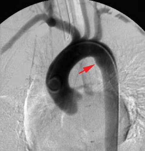 Figure 23.1. Normal Aortic Arch. Aortogram with “classic” origin pattern of the great vessels: right brachiocephalic artery, left common carotid artery, and left subclavian artery. Thoracic aortogram demonstrates normal variant fusiform dilatation (arrow) of the proximal descending aorta in the region of the ligamentum arteriosum representing a normal ductus bump. |
Congenital Anomalies. A number of congenital anomalies involve the arch and the branching pattern of the great vessels. The most striking is probably the right-sided aortic arch with mirror image branching, which has a 98% association with congenital heart disease, the vast majority being Tetralogy of Fallot. Therefore, most of these are considered congenital cardiac diseases and are often not associated with a more traditional vascular radiology practice. Two congenital anomalies are more often seen in an adult vascular radiology practice: left-sided (normal) arch with an aberrant right subclavian artery and pseudocoarctation (aortic kink) of the thoracic aorta.
Left arch with aberrant right subclavian artery (Fig. 23.2) is the most common arch anomaly being found in approximately
1% of individuals. It is rarely symptomatic. The right subclavian artery arises as a fourth branch of the arch and must cross the mediastinum to reach the right arm. It crosses behind the esophagus in 80% of cases, between the trachea and esophagus in 15%, and anterior to the trachea in 5% (Fig. 23.3A). A dilatation at the origin of the anomalous vessel is termed a diverticulum of Kommerell (Fig. 23.2). If large, it may cause significant posterior impression on the esophagus and result in dysphagia. The diagnosis can be confirmed with either CT or MR. Arteriography is rarely needed, but this anomaly may be encountered when angiography is being performed for other reasons such as cerebral angiography.
1% of individuals. It is rarely symptomatic. The right subclavian artery arises as a fourth branch of the arch and must cross the mediastinum to reach the right arm. It crosses behind the esophagus in 80% of cases, between the trachea and esophagus in 15%, and anterior to the trachea in 5% (Fig. 23.3A). A dilatation at the origin of the anomalous vessel is termed a diverticulum of Kommerell (Fig. 23.2). If large, it may cause significant posterior impression on the esophagus and result in dysphagia. The diagnosis can be confirmed with either CT or MR. Arteriography is rarely needed, but this anomaly may be encountered when angiography is being performed for other reasons such as cerebral angiography.
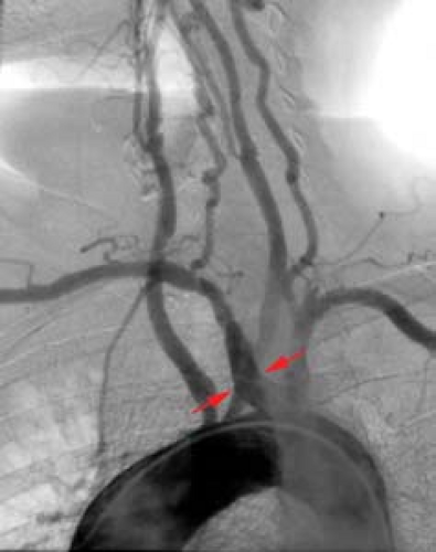 Figure 23.2. Aberrant Right Subclavian Artery. Aortogram demonstrating the origin of the right subclavian artery distal to the left subclavian. Note the dilation of the origin of the right subclavian artery representing a diverticulum of Kommerell (arrows). |
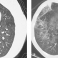
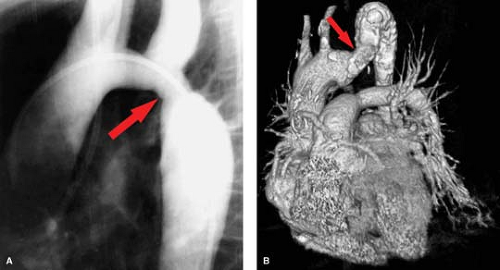 Figure 23.3. Coarctation of the Aorta. A. Aortic arch injection with “diffuse” type of coarctation (arrow), distal to the left subclavian artery. B. Reformatted CT angiogram of a 54-year-old male with pseudocoarctation of the aorta (arrow). Note the smooth narrowing, which did not have a significant gradient at cardiac catheterization. (Courtesy of Lynn M. Hurwitz, MD, Durham, NC.) |
Coarctation of the aorta is a primary abnormality of the media with eccentric narrowing of the aortic lumen due to infolding of the aortic wall (Fig. 23.3A). Approximately 70% are associated with congenital cardiac anomalies, the most common being bicuspid aortic valve. Pseudocoarctation (aortic kink) (Fig. 23.3B) of the thoracic aorta is a misnomer since it is a mild form of coarctation. The infolding occurs near the ligamentum arteriosum similar to the localized form of coarctation. Patients are asymptomatic due to the lack of a hemodynamically significant stenosis defined as a less than 10 mm Hg pressure gradient across the kink. The ascending aorta is elongated with a high, transverse arch and redundant descending portion distal to the kink. There is a similar incidence of associated bicuspid aortic valve.
Aortic Trauma. The mechanism of thoracic aortic injury consists of either blunt trauma or penetrating trauma or rarely a combination of both. Although certainly less common, penetrating trauma to the aorta can occur and is angiographically identical to penetrating injury to any vessel. Blunt trauma is far and away the most common trauma to the thoracic aorta and is most often the result of motor vehicle crashes and falls. The mechanism of blunt trauma is traditionally described as a result of sudden deceleration with tearing of the aorta at the junction of its fixed and mobile portions: proximal ascending aorta, just beyond the left subclavian (aortic isthmus), and just above level of diaphragm. Another popular theory involves compression to the chest that crushes the vascular structures while more recent data have proposed a combination of these two mechanisms.
Regardless of the mechanism of injury, aortic transection is a clinical emergency. Data from 1958, which combined clinical and autopsy statistics, reported that 85% of patients with aortic injury die at the accident scene. If untreated, most of the surviving 15% of injured patients will die within 3 days. Recent data indicates that with improvement in transport from the accident scene and prehospital treatment regimens, up to 50% of individuals with traumatic rupture of aorta reach the hospital alive. In addition, many of the subsequent in-hospital deaths are related to other serious concomitant injuries that inevitably occur in such serious trauma.
Aortography has been the gold standard for the diagnosis of thoracic aortic injury (Fig. 23.4A). Although relatively safe, it is time-consuming, costly, invasive, and resource-intensive. In near-complete aortic transection, one may be unable to easily pass the catheter beyond the injury site requiring a right brachial approach. Because of the lack of specific clinical indicators for aortic trauma, a large number of negative aortograms were performed. CT has replaced angiography as the initial radiographic diagnostic tool (following the chest radiograph) for blunt aortic injury. CT is widely available and trauma patients at risk for thoracic aortic injury often require other CT examinations, e.g., head and abdomen. Findings on CT for blunt aortic trauma fall into two main categories: indirect or direct signs of aortic injury. Indirect signs include evidence of mediastinal hemorrhage including poorly defined fat planes, perivascular hematoma, and periaortic hematoma. Direct signs of aortic injury include abnormal contour of the aorta, change in caliber of the aorta, contrast extravasation, and intraluminal irregularity (intimal flap) (Fig. 23.4B). Using these criteria, chest CT has been shown to be extremely valuable as a screening tool, with 100% sensitivity and 100% negative predictive value for thoracic aortic injuries in some series. Because the mechanism is often difficult to determine and the physical assessment often offers little diagnostic value in
these difficult patients, CT now prevents aortography in well over 90% of trauma patients.
these difficult patients, CT now prevents aortography in well over 90% of trauma patients.
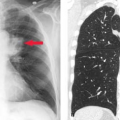
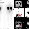
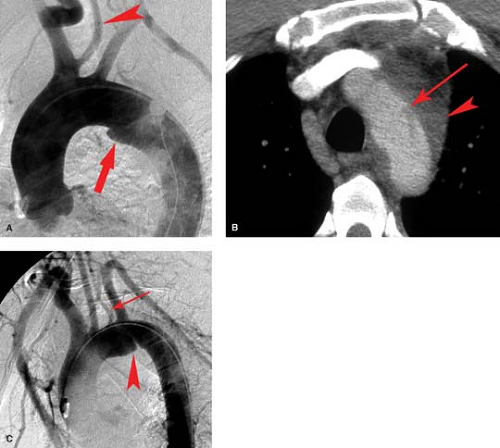 Figure 23.4. Thoracic Aorta. A. A 56-year-old female following a motor vehicle crash with mediastinal hemorrhage. Aortogram demonstrates a nonconvex area at the aortic isthmus suspected to be an aortic laceration (arrow). This was found to be a ductus bump at surgery. A normal variant aortic arch anatomy with common origin of the right brachiocephalic artery and left common carotid artery is also present (arrowhead). B. A 37-year-old male with blunt trauma to chest. CT demonstrates a large amount of mediastinal hemorrhage (arrowhead) in addition to an aortic laceration (arrow). C. Aortogram on the same patient confirms the aortic laceration (arrowhead) just distal to the left subclavian artery. Normal variant aortic arch anatomy with the origin of the left vertebral artery (arrow) from the aortic arch is also present. |
Criteria for performing aortography for suspected thoracic aortic injury is changing and is performed in most centers as part of endovascular treatment rather than open surgical repair. It is also used in the setting of great vessel injury, poor quality of the CT examination, or difficulty in determining the extent of injury. To that end, when endovascular repair is planned, aortography is only performed during the repair process rather than as a preliminary diagnostic study.
Angiographic findings of blunt aortic injury most often consist of an irregular outpouching just beyond the left subclavian artery representing the aortic pseudoaneurysm which is often bounded only by thin strands of adventitia or supported only by the adjacent mediastinum (Fig. 23.4C). Although 85% to 95% of aortic injuries found angiographically involve the aortic isthmus, one must also look for other vascular injuries in the thorax. This includes injury to the great vessels as well as injury to the aortic valve resulting in aortic insufficiency. When performing arch aortography, the proximal great vessels and diaphragm must be included in the images (Fig. 23.5). A retrospective review of 89 patients with blunt chest trauma and angiographic evidence of traumatic injury to the thoracic aorta or to its branches found that of 19% with ruptured aortic arch branches, 16% had an intact aorta and 3% had concomitant aortic rupture. More rarely, one may see a pseudoaneurysm of the ascending aorta just above the valve (often with aortic insufficiency) or just superior to the diaphragmatic hiatus. Frank extravasation at any of these sites is rare. A small aortic intimal tear may be the only angiographic finding occurring in less than 10% of thoracic aortic tears.
Equivocal findings occur in less than 5% of aortograms, mostly due to difficulties in distinguishing the ductus bump from the contour abnormality at the isthmus (Fig. 23.4A). Keys to telling the difference are that the ductus bump is very smooth and convex without acute margins. An aortic tear usually has acute margins, is irregularly shaped, and may have other associated abnormalities such as narrowing of the aorta, persistence of contrast in the outpouching, double densities, and presence of an intimal flap. It may be difficult in patients who have atherosclerosis, particularly plaque ulceration, to determine if the angiographic abnormality is a tear or atherosclerotic disease. The presence of atherosclerotic disease elsewhere, in light of the findings on CT, helps to confirm the diagnosis.
The treatment standard for traumatic aortic injury has been surgical grafting of the injured segment. This surgery is extensive with mortality rates of 30%, often due to other injuries related to the initial trauma. Paraplegia from open surgical repair occurs in almost 10% of patients. For these reasons, endovascular repair (stent grafting) of the injury is now preferred and is becoming widely applied. Problems continue with unexpanded device size, accurate placement, and maintaining patency of the left subclavian artery. Finally, if the
pseudoaneurysm of the aorta is not repaired and the tissues are strong enough to prevent rupture, a chronic saccular or fusiform pseudoaneurysm may form. Such psuedoaneurysms commonly calcify long-term and are often diagnosed on chest radiographs.
pseudoaneurysm of the aorta is not repaired and the tissues are strong enough to prevent rupture, a chronic saccular or fusiform pseudoaneurysm may form. Such psuedoaneurysms commonly calcify long-term and are often diagnosed on chest radiographs.
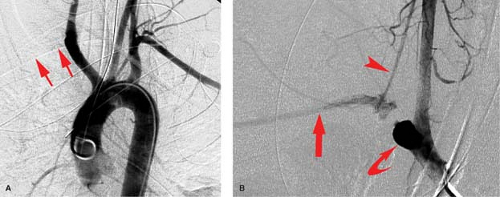 Figure 23.5. Injury to Great Vessels. A. A 23-year-old male in a motor vehicle crash. Aortogram shows normal arch but absence of the right subclavian (arrows). B. Selective injection of right brachiocephalic artery (curved arrow) shows obstruction of proximal right subclavian artery (straight arrow) with distal filling via small collateral (arrowhead). |
Aneurysms of the Thoracic Aorta. Thoracic aneurysms are best classified by the portion of the aorta involved, that is, the ascending, arch, or descending thoracic aorta. This anatomical distinction is important because it allows an etiological classification scheme. Regarding the aneurysms discussed here, those involving the ascending include cystic medial necrosis, Marfan, Ehlers–Danlos, and syphilitic (Fig. 23.6A–C). Aneurysms of the arch itself are more often atherosclerotic as are descending thoracic aortic aneurysms. Post-traumatic thoracic aortic aneurysms most often occur at the prevalent site of injury, the aortic isthmus, while mycotic aneurysms, although more commonly associated with the ascending, may occur anywhere along the course of the thoracic aorta.
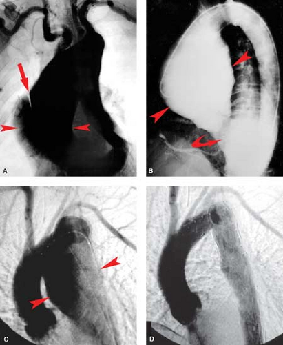 Figure 23.6. Thoracic Aortic Aneurysms. A. An 81-year-old patient with hypertension. Large ascending aortic aneurysm (between arrowheads) with dissection (arrow). Aneurysm was presumed to be from cystic medical necrosis. (Courtesy of Joseph M. Stavas, MD Durham, NC.) B. Marked dilation of the ascending aorta (between arrowheads) with associated aortic valvular regurgitation (curved arrow) is due to syphilis. C. Atherosclerotic aneurysm of descending aorta (arrowheads) in a 68-year-old male. D. Aneurysm has been successfully treated with an endograft. (Courtesy of Richard McCann, MD. Durham, NC.) |
Aneurysms of the ascending aorta constitute the majority of thoracic aneurysms (60%) followed by aneurysms of the descending aorta and much more rarely those of the arch and thoracoabdominal regions. A number of disease processes can lead to aneurysm formation of the thoracic aorta. A few of these however are highlighted in this chapter due to their frequency (cystic medial degeneration, atherosclerosis, inflammation) or characteristic radiographic findings (Marfan syndrome, Ehlers–Danlos syndrome). Aneurysms of the ascending aorta most often result from the cystic medial degeneration (cystic medial necrosis) (Fig. 23.6A). Cystic medial degeneration does occur in some patients with aging and appears to be accelerated by the presence of hypertension. In addition, the aortic manifestations of Marfan syndrome and Ehlers–Danlos syndrome (both described below) result from a form of cystic medial degeneration.
Related posts:
Stay updated, free articles. Join our Telegram channel

Full access? Get Clinical Tree


