Chapter 3 Three-Dimensional Transesophageal Echocardiography Systems
Introduction
Technologic advances continue to propel cardiac visualization forward. Advances in miniaturization, computer processing, and algorithms continue to have significant momentum. New acquisition technologies, coupled with the ability to process, display, and quantify enormous amounts of data, have pushed echocardiography forward into becoming a modality that will change cardiac intervention as well.1–13 Today, three-dimensional transesophageal echocardiography (3DTEE) has generated near-optical cardiac images. An understanding of cardiac mechanical motion in all of its spatial and temporal dimensions is providing valuable general physiologic insight for echocardiography as well as precise diagnoses for patients.
Transducer Technology
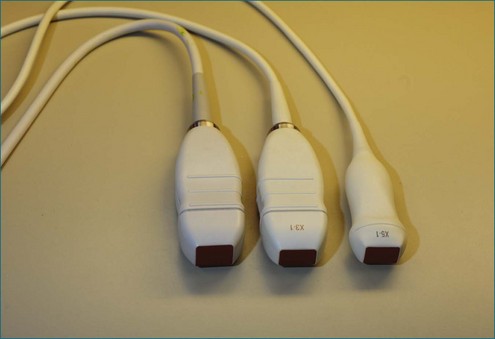
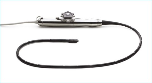
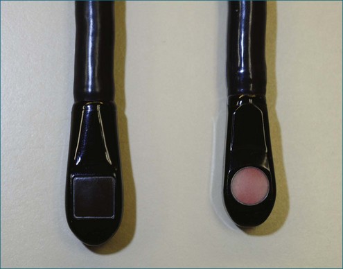
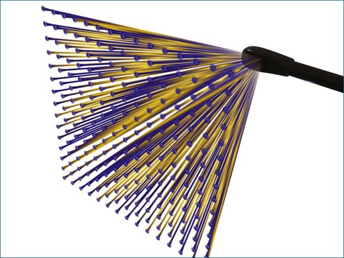
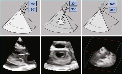
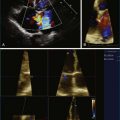
Conventional two-dimensional (2D) imaging, commonly used in echocardiography, uses transducers with several elements (Figure 3-1). Specifically, elements are oriented in a single row containing 48 to 128 elements, with each element electrically isolated from the others. Individual wavefronts are generated by firing elements in a certain sequence. Each element, constructively and destructively, adds and subtracts pulses, respectively, to generate a focused wave that has direction. This creates the radially propagated scan line. For example, if the farthest element on the right fires first and a timed sequence propagates along the element to the left, the beam will be steered to the left (Figures 3-2 and 3-3). Each element fires with a delay in phase with respect to a transmit initiation time. To further clarify this point, this one-dimensional array of elements can fire in two dimensions: radially and azimuthally (laterally). This spatiotemporal orientation of elements and their phase-timed firing sequence form the underpinning of any modern phased-array system.
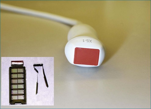
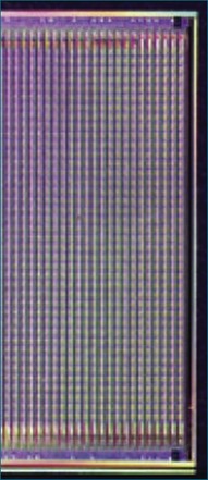
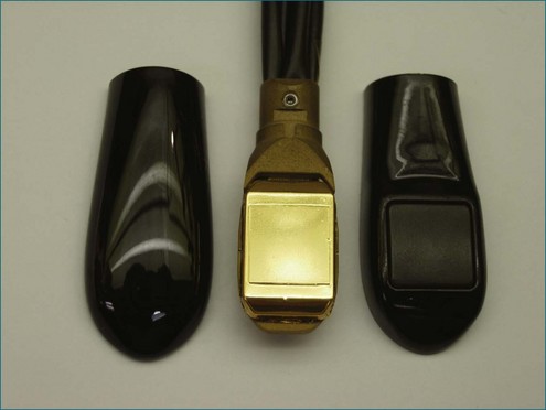
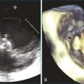
The key aspects pertinent to 3D echocardiography (3DE) imaging involve imaging moving structures. If a static structure that is not moving in space needs to be visualized, a 2D imaging transducer could be swept if the third spatial dimension could be additionally registered within the coordinate space. By using electromagnetic trackers, early gated 3D methodologies exploited this paradigm. Naturally, the 2D images needed to be gated to the electrocardiogram (ECG). This could lead to error caused by movement or arrhythmias, and these lengthy scans could take tens of minutes, requiring a few hundred heart cycles. Ultimately, high-resolution cardiac imaging requires instantaneous imaging to overcome these limitations. The key difference between a 2D imaging transducer and an instantaneous 3D imaging transducer is the arrangement of elements (Figures 3-4 to 3-7). Although a one-dimensional row is used for 2D imaging, a 2D matrix or checkerboard is used to steer an ultrasound scan line in the azimuthal as well as the elevational direction. A conventional 2D imaging transducer of one row steers energy in the azimuthal plane but unintentionally propagates elevational energy above and below the scanning plane. This checkerboard pattern allows phasic firing of elements to generate a radially propagated scan line that can be steered laterally and in elevation. Thus, the true 3D imaging transducer is born.
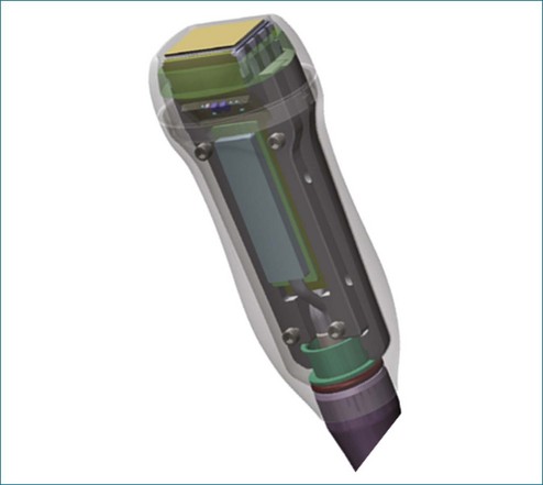
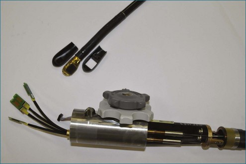
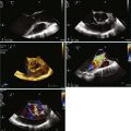
3DE depends on micro-beamforming miniaturization. By reducing the electronic substrate required to beamform onto a single chip, the transducer chip is miniaturized sufficiently to pass into the human esophagus. It also significantly reduces the power requirement and hence the amount of heat generated by live circuitry (Figures 3-8 to 3-10).
Beamforming
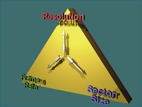
Ultimately, the constraint of a system can be described by a triangle whose boundaries are defined by the number of transmit lines that can be fired. Lines widely spaced can increase the volume size at the cost of lowering the resolution for a constant frame rate (Figure 3-11). Tight line spacing can be used in zoom modes to increase resolution, but at the price of a smaller volume. The number of transmit lines is a key determinant of frame rate; more lines increase the resolution but lower the frame rate.
Stay updated, free articles. Join our Telegram channel

Full access? Get Clinical Tree


