Three-Dimensional Ultrasound: Techniques and Clinical Applications


Abstract


Fetal anatomy is three-dimensional, but cross-sections obtained during real-time ultrasound examination are merely an artificial reduction of anatomy. They attempt to capture a standard view or the essence of a particular pathology. Acquisition of a good ultrasound volume is not trivial, but a comprehensive volume may enable examination at a greater level of detail than is possible from a single cross-section. In this sense, volume ultrasound is similar to a video in that multiple different neighboring sections are displayed. This chapter explain how three-dimensional ultrasound can be used practically in obstetric imaging.


Keywords

3D ultrasound, advanced CNS evaluation, STIC, surface rendering


Introduction


Fetal anatomy is three-dimensional (3D). Cross-sections obtained during real-time ultrasound (US) examination are an artificial reduction of anatomy to produce one still image, created to capture a standard view or the essence of a particular pathology. Acquisition of a good US volume is not trivial, but a comprehensive volume may enable examination at a greater level of detail than is possible from a single cross-section; this is similar to a video in that multiple different neighboring sections are displayed.


Volume Displays


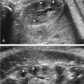
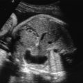
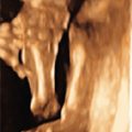
Three-dimensional US volumes can be analyzed visually in two principal ways: by viewing cross-sections or surface-rendered views. Cross-sections (planes placed anywhere in the volume) are viewed in either one single plane or two/three (typically orthogonal) planes. The latter is usually called multiplanar display ( Fig. 173.1 ). Before examining the anatomy, the multiplanar display should be used to align the volume according to standard planes ( Fig. 173.2 [face acquire, align]). A curved section can also be placed to follow anatomic structures that do not lie in a straight plane, such as the fetal palate ( Fig. 173.3 ). A display of a number of parallel cross-sections is usually called tomographic display ( Fig. 173.4 ). Surface-rendered views are formatted to display tissue interfaces, either of soft tissue (e.g., the facial skin surface, seen from the amniotic fluid cavity) or bone (e.g., the skull bones, seen from the outside or inside), or a mixture of both ( Fig. 173.5 ).


Fig. 173.1


Multiplanar display of the head of a normal fetus at 44 mm crown-rump length (corresponding to 11 postmenstrual weeks). The volume was acquired transvaginally with a median section and aligned anatomically. The reference dot is positioned in the third ventricle, and volume contrast enhancement (1 mm slice thickness) was used. (A) Multiplanar display of axial, coronal, and sagittal sections. (B) Sagittal section, reformatted from the same volume (selected anatomic structures labeled).


Fig. 173.2


Systematic approach to volume acquisition and stepwise alignment and rotation to extract the exact median section of a normal fetal face at 21 weeks’ gestation (3). This volume was obtained from a fetus whose profile could not be obtained using real-time scanning because the fetus was facing to the side. First, the closest possible section to the profile was selected as the starting scan. Panels B to E show the stepwise extraction and eventually, analysis of the profile. (A) After volume acquisition a data block is stored, but usually not displayed. To understand the alignment better the entire volume block is shown, and the volume scan starting plane (red) and the range plane (blue) are indicated. (B) The reference dot is the intersection of the three orthogonal planes (highlighted as a red dot in near-sagittal, axial, and frontal sections in panels A, B, and C). In the multiplanar display the reference dot is placed on an easily recognizable structure, e.g., the tip of the nose. (C) Using the volume rotation in panel B, the direction of the nose is turned upright (red and green arrows), using rotation around the Z-axis (so-called in-plane rotation). (D) Then, the apparent nonalignment in panel C is adjusted to show the frontal view, using rotation around the X-axis in plane C. (E) Finally, the perfectly aligned, exactly median profile is rotated upright and studied, using the maxilla-nasion-mandible angle (blue lines) and the facial profile line (yellow line).


Fig. 173.3


Reconstruction of the normal fetal palate, using a curved plane. A frontal insonation of the fetal profile with transducer parallel to the frontal edges of the maxilla and the mandible was used to acquire the volume. The curved reconstruction plane (placement shown by the purple line in the sagittal section [A]) displays the entire hard and the soft palate down to the uvula in (B).

(From Tutschek B, Blaas HG, Abramowicz J, Baba K, Deng J, Lee W, et al. Three-dimensional ultrasound imaging of the fetal skull and face. Ultrasound Obstet Gynecol [Epub ahead of print], 2017.)


Fig.173.4


Tomographic imaging of a normal fetal profile. Narrow spacing of the adjacent sections permits differentiation between the nasal bones (blue circles, images −1 and 1) and the maxillary processes (red circles, images −3 and 4) on both sides.

(From Tutschek B, Blaas HG, Abramowicz J, Baba K, Deng J, Lee W, et al. Three-dimensional ultrasound imaging of the fetal skull and face. Ultrasound Obstet Gynecol [Epub ahead of print], 2017.)


Fig. 173.5


Three-dimensional US surface rendering of the fetal face. All images in this figure were reformatted from the same volume that had been acquired using frontal insonation. For such a volume, ideally at least a small amount of amniotic fluid should be present between the face and other echogenic structures beneath the transducer. (A) Sagittal and axial sections: the adjustable render box (white lines) determines what the algorithm will display in 3D. The green line defines the direction of rendering (not necessarily, but in this example also the direction from which the object is viewed), in this example from the front. The blue arrows define the soft tissues seen in the display in (B), the yellow arrows define the bones. (B) The same volume can be “rendered” (surface-reconstructed) for either the skin surface (“100% skin,” far left) or the bone surface (“100% bone,” far right), or a mix of both. Note the absent ossification of both nasal bones apparent in the far-right image of (B) in this fetus with trisomy 21.

(From Tutschek B, Blaas HG, Abramowicz J, Baba K, Deng J, Lee W, et al. Three-dimensional ultrasound imaging of the fetal skull and face. Ultrasound Obstet Gynecol [Epub ahead of print], 2017.)


Technique


It is a misunderstanding and oversimplification to assume that any volume containing the structures of interest will enable extraction of diagnostic images. Three main aspects, each of which requires physical knowledge and careful execution, determine the diagnostic quality of successful 3D US: volume acquisition and alignment; volume contrast enhancement; and possibly, surface rendering.


Acquiring and Aligning a Volume


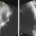
Successful 3D US first requires optimization of the two-dimensional (2D) image. The correct starting insonation angle with regard to the structure(s) of interest is of paramount importance. Not all sections that can be reformatted (extracted) from a 3D volume have the same resolution. In diagnostic US, the axial resolution (in the axis directed perpendicular away from the transducer) is better than the lateral resolution. Therefore the resolution in the acquisition plane (also called azimuth plane) is best; this plane is typically displayed in panel A directly after volume acquisition. The so-called range plane (blue plane in Fig. 173.2A ), which cannot be obtained in real-time scanning by simply rotating the transducer, offers the lowest resolution, yet it often contains valuable information that cannot be obtained by maneuvering the transducer on the maternal abdomen, or in case of transvaginal scanning, in the vagina.


The starting plane for a volume acquisition should be placed to show the structures of interest as well as possible. Then the volume is acquired and initially displayed in the multiplanar mode (showing three orthogonal planes: A, B, and C; Fig. 173.6 ). Each of these planes can be aligned, using rotation around the X, Y, and Z axes, respectively, to achieve the intended orientation, typically in standard anatomic sectional planes. A clinical example of this workflow for the fetal face is shown in Fig. 173.2 .


Fig. 173.6


Still image from a real-time scan to examine the foot of a normal 20-week fetus using volume contract enhancement. The regular cross-sectional image is shown on the left, and the three-dimensional ultrasound image with volume contrast enhancement on the right. In the left panel, the foot can be seen, and a few of the small bones are apparent. Real-time volume contrast enhancement (right panel) visualizes both the soft tissue as well as all mineralized bones from all toes and the middle foot that lie in different, but neighboring, sections. The slice thickness used for this example was 5 mm.

Only gold members can continue reading. Log In or Register to continue

Stay updated, free articles. Join our Telegram channel

Jul 7, 2019 | Posted by in OBSTETRICS & GYNAECOLOGY IMAGING | Comments Off on Three-Dimensional Ultrasound: Techniques and Clinical Applications

Full access? Get Clinical Tree

Get Clinical Tree app for offline access