, as measured along the central axis of the entire array, and the focal distance, F, as measured along this axis (see Fig. 5.1a and b). For both cases shown in Fig. 5.1 the distance from the center of the array to the center of the first element is  , where 2B is the total length of the array, 2b is the length of an element, and s is the pitch of the array (see Eq. (4.5)). The quantity
  will appear frequently in our delay law expressions so we will abbreviate that quantity as
  :
:
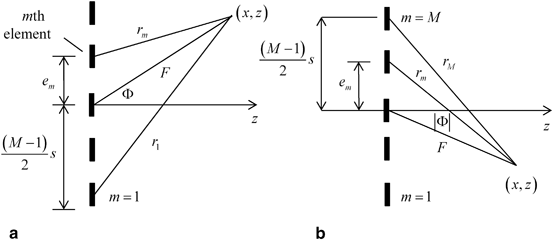
Fig. 5.1
a Geometrical parameters for steering and focusing an array when  , and b when
 , and b when

(5.1)
The distance to the centroid of the mth element,  , in terms of
  is then
 , in terms of
  is then
![$$ {{e}_{m}}=[ (m-1)-\bar{M} ]s. $$](/wp-content/uploads/2016/05/A314073_1_En_5_Chapter_Equ2.gif)
(5.2)
Consider first the case when  (Fig. 5.1a). To obtain the delay law to steer and focus the beam to the point
  we first calculate the times it takes to propagate from the centroid of the mth element to
  ,
,  , where c is the wave speed. If we apply the negative of these times (representing time advances) to all the elements then all of the waves from the elements will arrive at
  at the same time. To turn this result into a proper delay law we must also add a positive, constant term so that all of these time values are time delays, not advances. It is obvious from Fig. 5.1a that the distance from the first element to
  ,
,  , is the largest distance for the entire array, so that a proper delay law is simply
 (Fig. 5.1a). To obtain the delay law to steer and focus the beam to the point
  we first calculate the times it takes to propagate from the centroid of the mth element to
  ,
,  , where c is the wave speed. If we apply the negative of these times (representing time advances) to all the elements then all of the waves from the elements will arrive at
  at the same time. To turn this result into a proper delay law we must also add a positive, constant term so that all of these time values are time delays, not advances. It is obvious from Fig. 5.1a that the distance from the first element to
  ,
,  , is the largest distance for the entire array, so that a proper delay law is simply
(5.3)
From the geometry of Fig. 5.1a and the law of cosines, we then have

(5.4)
and the delay law becomes
![$$ \Delta {{t}_{d}}=\frac{1}{c}[ \sqrt{{{F}^{2}}+{{( \bar{M}s )}^{2}}+2F\bar{M}s\sin \Phi }-\sqrt{{{F}^{2}}+{{( {{e}_{m}} )}^{2}}-2F{{e}_{m}}\sin \Phi } ]. $$](/wp-content/uploads/2016/05/A314073_1_En_5_Chapter_Equ5.gif)
(5.5)
In comparison, for  , if we use the geometry of Fig. 5.1b we find instead
 , if we use the geometry of Fig. 5.1b we find instead
![$$ \begin{aligned} \Delta {{t}_{d}}={{r}_{M}}/c-{{r}_{m}}/c \\& =\frac{1}{c}[ \sqrt{{{F}^{2}}+{{(\bar{M}s)}^{2}}+2F\bar{M}s\sin \left| \Phi\right|}-\sqrt{{{F}^{2}}+{{({{e}_{m}})}^{2}}+2F{{e}_{m}}\sin \left| \Phi\right|} ].\end{aligned} $$](/wp-content/uploads/2016/05/A314073_1_En_5_Chapter_Equ6.gif)
(5.6)
It should be noted that although Fig. 5.1 shows a geometry for an array with an odd number of elements, there is nothing in the expressions used in the derivation that restricts our results to that case and so these delay laws are valid for arrays with either an even or odd number of elements. Azar et. al. [1] used a similar approach to develop these delay laws, which are also applicable to linear arrays operating in a 3-D setting since such arrays can only be steered and focused in a plane with the 2-D delay laws given here .
We can compare these exact laws with our previous results which used the paraxial approximation . If we are focusing the beam to a point well removed from the face of the array then we can expand Eqs. (5.5) and (5.6) for F large and obtain to second order (keeping three terms in the expansion as shown in Eq. (2.42)) For  we find
 we find
![$$ \begin{aligned} \Delta {{t}_{d}}=\frac{F}{c}\left[ \sqrt{1+\frac{{{(\bar{M}s)}^{2}}+2F\bar{M}s\sin \Phi }{{{F}^{2}}}}-\sqrt{1+\frac{{{({{e}_{m}})}^{2}}-2F{{e}_{m}}\sin \Phi }{{{F}^{2}}}} \right] \\& \cong \frac{F}{c}\left[ 1+\frac{{{(\bar{M}s)}^{2}}+2F\bar{M}s\sin \Phi }{2{{F}^{2}}} \right.-\frac{1}{8}\frac{4{{(\bar{M}s)}^{2}}{{\sin }^{2}}\Phi }{{{F}^{2}}} \\& \left. -1-\frac{{{({{e}_{m}})}^{2}}-2F{{e}_{m}}\sin \Phi }{2{{F}^{2}}}+\frac{1}{8}\frac{4{{({{e}_{m}})}^{2}}{{\sin }^{2}}\Phi }{{{F}^{2}}} \right],\end{aligned} $$](/wp-content/uploads/2016/05/A314073_1_En_5_Chapter_Equ7.gif)
(5.7)
whereas for  we have
 we have
![$$ \begin{aligned} \Delta {{t}_{d}}=\frac{F}{c}\left[ \sqrt{1+\frac{{{(\bar{M}s)}^{2}}+2F\bar{M}s\sin \left| \Phi\right|}{{{F}^{2}}}}-\sqrt{1+\frac{{{({{e}_{m}})}^{2}}+2F{{e}_{m}}\sin \left| \Phi\right|}{{{F}^{2}}}} \right] \\& \cong \frac{F}{c}\left[ 1+\frac{{{(\bar{M}s)}^{2}}+2F\bar{M}s\sin \left| \Phi\right|}{2{{F}^{2}}} \right.-\frac{1}{8}\frac{4{{(\bar{M}s)}^{2}}{{\sin }^{2}}\Phi }{{{F}^{2}}} \\& \left. -1-\frac{{{({{e}_{m}})}^{2}}+2F{{e}_{m}}\sin \left| \Phi\right|}{2{{F}^{2}}}+\frac{1}{8}\frac{4{{({{e}_{m}})}^{2}}{{\sin }^{2}}\Phi }{{{F}^{2}}} \right].\end{aligned} $$](/wp-content/uploads/2016/05/A314073_1_En_5_Chapter_Equ8.gif)
(5.8)
Using the definition of  and
and  from Eqs. (5.1) and (5.2) and collecting terms and simplifying we obtain, for
 and
and  from Eqs. (5.1) and (5.2) and collecting terms and simplifying we obtain, for
![$$ \Delta {{t}_{d}}\cong \frac{1}{c}\left[ \frac{(m-1)(M-m){{s}^{2}}{{\cos }^{2}}\Phi }{2F}+(m-1)s\sin \Phi\right], $$](/wp-content/uploads/2016/05/A314073_1_En_5_Chapter_Equ9.gif)
(5.9)
and, for 

![$$ \Delta {{t}_{d}}\cong \frac{1}{c}\left[ \frac{(m-1)(M-m){{s}^{2}}{{\cos }^{2}}\Phi }{2F}+(M-m)s\sin \left| \Phi\right| \right], $$](/wp-content/uploads/2016/05/A314073_1_En_5_Chapter_Equ10.gif)
(5.10)
which are a combination of the steering laws and focusing laws developed previously in the paraxial approximation (see Eqs. (4.35) and (4.39) and let  and
and  ).
).
 and
and  ).
).If we want to use the combined steering and focusing laws of Eqs. (5.5) and (5.6) for steering only, we have to let  . It can be seen from Eqs. (5.9) and (5.10) that we do recover the proper limit but only because of canceling infinities in Eqs. (5.7) and (5.8), a procedure which is difficult to implement in software. Thus, it is best to treat steering only as a special case.
 . It can be seen from Eqs. (5.9) and (5.10) that we do recover the proper limit but only because of canceling infinities in Eqs. (5.7) and (5.8), a procedure which is difficult to implement in software. Thus, it is best to treat steering only as a special case.
Parameterization of the delay laws by specifying  is a logical choice but another convenient way to design the delay law is to specify the point
  in the medium to which we want to steer and focus the beam. Since
  , we could specify that point and then use these relations in the delay laws Eqs. (5.5) and (5.6). However, we could also simply write the time delay as
 is a logical choice but another convenient way to design the delay law is to specify the point
  in the medium to which we want to steer and focus the beam. Since
  , we could specify that point and then use these relations in the delay laws Eqs. (5.5) and (5.6). However, we could also simply write the time delay as
(5.11)
which will also give a proper delay law.
The function td = delay_laws2D(M, s, Phi, F, c) discussed in the last Chapter (Code Listing C.12) implements Eqs. (5.5) and (5.6) to generate the delays, td, in microseconds needed to produce steering to a focal point at an angle  (Phi) (in degrees) and focusing at a distance F (in mm) for an array of M elements with a pitch, s, (in mm) and for a medium of wave speed c (in m/s). If F is specified as infinity (F = inf) the steering only delay law of Eq. (4.35) is used instead.
 (Phi) (in degrees) and focusing at a distance F (in mm) for an array of M elements with a pitch, s, (in mm) and for a medium of wave speed c (in m/s). If F is specified as infinity (F = inf) the steering only delay law of Eq. (4.35) is used instead.
5.2 Steering and Focusing Through a Planar Interface
As seen in the last section, in a single medium it is relatively simple to set up the general time delay law based on the angle of beam steering (from the center of the transducer) and the desired focal point. In radiation through a plane interface, however, the relationship becomes more complex, particularly when focusing is involved.
We will begin by considering the case of beam steering only for the configuration shown in Fig. 5.2 where an array radiates at an angle through a plane interface. This type of setup can be used to model an immersion test where the array is placed in a water bath and radiates into a solid component or in an angle beam inspection where the array sits on a plastic wedge and radiates into the solid. In either of those cases the wave speed of second medium is larger, i.e.  as shown in Fig. 5.2. At high frequencies, each element of the array will radiate a wave field through the interface that will satisfy Snell’s law [Schmerr]. Figure 5.2 shows a ray path of a wave that travels from the center point C of the array along a direction normal to the face of the array in the first medium and is refracted into the second medium at an angle
  . Just as we used the z-axis as the reference axis for no steering in a single medium we will use this central ray axis to define the case of no steering in this configuration. From Snell’s law, then the refracted angle,
  , for the no steering case must satisfy
 as shown in Fig. 5.2. At high frequencies, each element of the array will radiate a wave field through the interface that will satisfy Snell’s law [Schmerr]. Figure 5.2 shows a ray path of a wave that travels from the center point C of the array along a direction normal to the face of the array in the first medium and is refracted into the second medium at an angle
  . Just as we used the z-axis as the reference axis for no steering in a single medium we will use this central ray axis to define the case of no steering in this configuration. From Snell’s law, then the refracted angle,
  , for the no steering case must satisfy
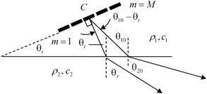
Fig. 5.2
A phased array radiating at oblique incidence to a planar interface, showing a reference ray that is normal to the face of the array and a ray which makes a specified angle,  , relative to the normal of the interface
 , relative to the normal of the interface
(5.12)
Stay updated, free articles. Join our Telegram channel

Full access? Get Clinical Tree


