. We can express in spherical coordinates
 as
as . Steering of the beam in this direction can be accomplished by applying a linearly varying time shift,
 , over the face of the array and evaluating that phase at the centroids of the individual elements. This results in the shifts,
 given by
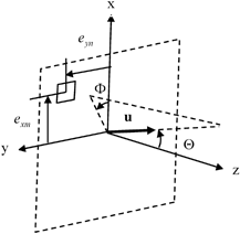
Fig. 8.1
Parameters for steering a beam of a 2-D array in the direction of the unit vector, u

(8.1)
The centroid locations are given by
![$$\begin{aligned}& {{e}_{xm}}=\left[ \left( m-1 \right)-\bar{M} \right]{{s}_{x}} \\& {{e}_{yn}}=\left[ \left( n-1 \right)-\bar{N} \right]{{s}_{y}}, \\\end{aligned}$$](/wp-content/uploads/2016/05/A314073_1_En_8_Chapter_Equ2.gif)
(8.2)
where are the pitches of the elements in the x– and y-directions, respectively, and M and N are the number of elements in the x– and y-directions, and where
 are the pitches of the elements in the x– and y-directions, respectively, and M and N are the number of elements in the x– and y-directions, and where
(8.3)
Since the delays in Eq. (8.1) contain both positive and negative values, we can simply add a constant delay equal to the magnitude of largest negative value to obtain a proper time delay law, , given by
 , given by
(8.4)
8.2 Beam Steering and Focusing in 3-D
We can also consider steering and focusing of the array wave field to a point, P, in the surrounding medium specified by the focal distance , F, and the steering angles as shown in Fig. 8.2. In this case, the distance,
 , from an element to P is given from the geometry as
 as shown in Fig. 8.2. In this case, the distance,
 , from an element to P is given from the geometry as
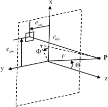
Fig. 8.2
Parameters for steering and focusing a 2-D array at a point, P, as defined by the focal distance, F, and the angles


(8.5)
A proper delay law, , can then be obtained from
 , can then be obtained from
(8.6)
where c is the wave speed.
The MATLAB® function delay_laws3D (Code Listing C.22) implements the beam steering delay law of Eq. (8.4) and the steering/focusing law of Eq. (8.6) for a 2-D array. The function call is :
td = delay_laws3D (M, N, sx, sy, theta, phi, F, c);
where td is the matrix of delay times (in μs) for an array with M elements in the x-direction and N elements in the y-direction. The pitches of the array are and
and in the x– and y-directions, respectively (in mm), the steering angles
 , and
, and (in degrees), the focal distance is F (in mm), and the wave speed of the medium is c (in m/s). Figures 8.3–8.5 show some samples of delay laws for an array radiating into water (c = 1480 m/s) with M = 8, N = 16 elements,
 . Figure 8.3 shows the case of steering only parallel to the y-axis with
 , while Fig. 8.4 is for steering angles
 so that the steering is parallel to the x-axis. As seen in these figures in both these cases the time delays are purely the linear functions contained in Eq. (8.1). Figure 8.5 instead considers the case of focusing only of this same array where
 ,
, . In this case, there are approximately quadratic variations in the time delays in both the x– and y-directions .
 and
and in the x– and y-directions, respectively (in mm), the steering angles
 , and
, and (in degrees), the focal distance is F (in mm), and the wave speed of the medium is c (in m/s). Figures 8.3–8.5 show some samples of delay laws for an array radiating into water (c = 1480 m/s) with M = 8, N = 16 elements,
 . Figure 8.3 shows the case of steering only parallel to the y-axis with
 , while Fig. 8.4 is for steering angles
 so that the steering is parallel to the x-axis. As seen in these figures in both these cases the time delays are purely the linear functions contained in Eq. (8.1). Figure 8.5 instead considers the case of focusing only of this same array where
 ,
, . In this case, there are approximately quadratic variations in the time delays in both the x– and y-directions .
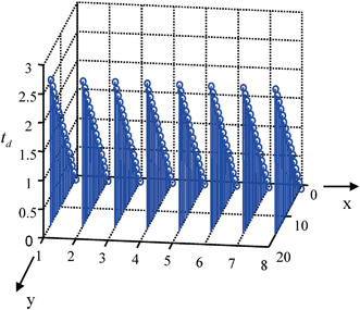
Fig. 8.3
Time delays, , (in μs) for steering the beam of a 2-D array parallel to the y-axis with M = 8,N = 16 elements,
 , and
, and

 , (in μs) for steering the beam of a 2-D array parallel to the y-axis with M = 8,N = 16 elements,
 , and
, and

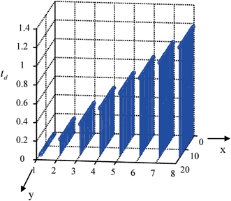
Fig. 8.4
Time delays, , (in μs) for steering the beam of a 2-D array parallel to the x-axis with M = 8,N = 16 elements,
 , and
, and

 , (in μs) for steering the beam of a 2-D array parallel to the x-axis with M = 8,N = 16 elements,
 , and
, and

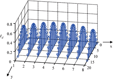
Fig. 8.5
Time delays, , (in μs) for focusing the beam of a 2-D array along the z-axis with M


 , (in μs) for focusing the beam of a 2-D array along the z-axis with M
Stay updated, free articles. Join our Telegram channel

Full access? Get Clinical Tree


