2 Traumatology
Fractures
Definition
A fracture represents a complete or incomplete interruption of the continuity of bone with or without dislocation following direct or indirect force.
Pathology
Types of fractures
 Soft-tissue damage:
– Closed fracture
– Compound fracture
 Position of the fracture fragments:
– Displaced fracture
– Undisplaced fracture
Description of fractures
 Complete fractures:
– Chisel fracture
– Transverse fracture
– Oblique fracture
– Bow fracture
– Torsion or spiral fracture
– Segmental fracture
– Comminuted fracture
– Crash fracture (more than six fragments)
 Incomplete fractures:
– Infraction
– Fissure
Clinical Findings
 Deformity
 Abnormal mobility
 Crepitation
 Loss of function
 Local pain
 Local swelling
Diagnostic Evaluation

 Location and extent of the fracture
 Description of the fracture:
– Complete (simple fracture, crash fracture)
– Incomplete (fissure, infraction)
 Location of the fracture line (articular involvement)
 Position of the fracture fragments:
– Lateral displacement
– Axial displacement
– Peripheral displacement
 Determination of the fracture type (AO classification)
 Caution: Operator dependent
 Associated injuries:
– Instability
– Rotator-cuff injuries
– Bicipital tendon injuries
– Hematomas
– Bursitis
– Joint effusion
 Functional assessment
 Hill-Sachs lesion
 Avulsion of the greater tuberosity
 Fracture of the humeral head
 Separation of the acromioclavicular (AC) joint

 Addition to projectional radiography (modifying the description of the fracture)
 Number, position, and relationship of the fracture fragments
 Articular involvement
 Rotatory displacement (antetorsion angle) and length discrepancy
 Surgical planning (2-D and 3-D reconstructions)
 Injuries of the labrum and joint capsule (computed tomography [CT]) arthrography)
 Associated injuries:
– Instabilities
– Rotator-cuff injuries
– Bicipital tendon injuries
– Hematomas
– Bursitis
– Joint effusion

 Fatigue fracture (stress fracture)
 Occult fracture (bone bruise)
 Chondral fracture
 Associated injuries:
– Instabilities
– Rotator-cuff injuries
– Bicipital tendon injuries
– Hematomas
– Bursitis
– Joint effusion
 Functional assessment
Causes of Fractures
Traumatic Fractures
Definition
Traumatic fracture refers to a complete or incomplete break in the continuity of the bone caused by a direct or indirect sudden excessive strain on the physiological elasticity of the healthy bone.
Pathology
 Macroscopic:
– Bone-marrow hematoma
– Continuity break
– Associated soft-tissue injuries
 Microscopic:
– Hemorrhage and edema
– Trabecular compression zones with continuity break
Clinical Findings
 Functional impairment
 Deformity
 Crepitation
 Local pain
 Local swelling
Goals of Imaging
 Delineation of the fracture fragments
 Relationship of the fracture fragments
 Possibility of a fracture classification
 Visualization of possible associated injuries
Therapeutic Principles
 Depending on the fracture type, conservative or surgical therapy
Diagnostic Evaluation
 (→ Method of choice)
Recommended views
 Standard projections:
– Anteroposterior (AP) view in relation to the scapula
– Tangential view of the glenoid fossa
– Axial view
– Transscapular view (“Y projection”)
– Transthoracic view
 Special projections (depending on the location of the fracture):
– AP view in abduction or elevation and external rotation (“Stryker’s notch view”)
– Oblique apical view
– Supraspinal outlet view
 Conventional tomography (position of the fragments and course of the fracture lines in complex fractures)
Findings
 Fracture lines in the region of the humeral head and neck, clavicle and scapula
 Hill-Sachs lesion
 Humeral head compression
 Bankart lesion
 Instability
 Fat-fluid level
 (→ Supplementary method)
Recommended planes
 Posterior transverse and longitudinal section
 Lateral longitudinal section (coronal view)
 Anterior and anteromedial transverse view
 Longitudinal section through the AC joint
Findings
 Sharply demarcated or shallow concave “indentation” of the humeral head (Hill-Sachs lesion and humeral head fracture)
 (→ Supplementary method)
Recommended protocol
 Standard CT:
– Section thickness: 2–3 mm
– Table feed: 2–3 mm
 Spiral CT:
– Section thickness: 1–3 mm
– Table feed: 2–5 mm
– Increment: 1–3 mm
Findings
 Position and number of fragments
 Involvement of the articular surface (e.g., Bankart lesion)
 (→ Supplementary method)
Recommended sequences
 Short time inversion recovery (STIR) sequence
 T1- and T2-weighted tubo spin-echo (TSE) sequences (possibly with fat suppression)
 Administration of contrast medium only to delineate the fracture cleft
Findings
 T1-weighted spin-echo (SE) sequence:
– Hypointense visualization of the fracture cleft
– Diffuse hypointense visualization of the associated bone-marrow hematoma/edema
 T2-weighted SE sequence:
– Hyperintense visualization of the fracture line
– Diffuse hyperintense visualization of the associated bone-marrow hematoma/edema
 T1-weighted sequence after administration of contrast medium:
– Strong diffuse contrast enhancement in the region of the associated bone-marrow hematoma/edema with hypointense demarcation of the fracture line
Pathological Fracture
Goals of Imaging
 Extension of the pathological process: intra-articular and/or extra-articular
 Local stability
 Additional soft-tissue involvement
Definition
Complete or incomplete break in the continuity of a locally or diffusely (insufficiency fracture) altered bone without adequate trauma (spontaneous fracture) or following an inadequate trauma.
Pathology
 Macroscopic:
– Bone-marrow hematoma
– Break in continuity with smoothly demarcated fracture ends, diastatic fracture line
– Associated soft-tissue injuries
– Destruction of the bone by the underlying disease process (osteoporosis, metastases, osteomyelitis, primary tumor, Paget disease)
 Microscopic:
– Hemorrhage and edema
– Trabecular compression zones with discontinuity
– Absent callus formation
– Specific histological documentation
Clinical Findings
 Functional impairment
 Deformity
 Crepitation
 Local pain
 Local swelling (possibly caused by the underlying pathology)
Diagnostic Evaluation
 (→ Initial method of choice)
Recommended views
 Standard views
 Special views (depending on the fracture location)
 Conventional tomography (position of the fragments and course of the fracture lines in complex fractures)
Findings
 Smoothly outlined fracture lines in the region of the humeral head and neck, clavicle and scapula, frequently dehiscent fracture cleft, absent callus formation
 Detectable soft-tissue density

Recommended planes
 Posterior transverse and longitudinal sections
 Lateral longitudinal (coronal) section
 Anterior and anteromedial transverse section
 Longitudinal section through the AC joint
Findings
 Abrupt or shallow concave “indentation” at the fracture site
 Anechoic, hypoechoic, and hyperechoic soft-tissue formation (tumor mass and accompanying reaction)
 (→ Supplementary method)
Recommended protocol
 Standard parameters
Findings
 Location and number of fragments
 Detection of osseous destruction
 Detection of a soft-tissue mass
 (→ Method of choice for DD)
Recommended sequences
 STIR sequence
 T1- and T2-weighted sequences (possibly with fat suppression)
 Administration of contrast medium to delineate the fracture line and to visualize the intramedullary and extramedullar/ tumor component)
Findings
 T1-weighted SE sequence:
– Hypointense visualization of the fracture line
– Diffuse hypointense visualization of the associated bone-marrow hematoma and edema
– Hypointense and/or hyperintense visualization of the intramedullary and extramedullary soft-tissue component of the tumor
 T2-weighted SE sequence:
– Hyperintense visualization of the fracture line and the peritumoral edema
– Diffuse hyperintense visualization of the associated bone-marrow hematoma and edema
– Hypointense and/or hyperintense visualization of the intramedullary and extramedullary soft-tissue component of the tumor
 T1-weighted sequence after administration of contrast medium:
– Strong diffuse enhancement in the region of the associated bone-marrow hematoma/edema with hypo-intense demarcation of the fracture line
– Contrast enhancement in the region of the soft-tissue component of the tumor
Therapeutic Principles
Depending on the pathology, joint preservation or joint replacement therapy:
 Joint preservation: Internal fixation
 Joint replacement: Proximal humerus prosthesis, humerus prothesis, allograft reconstruction, composite allograft reconstruction, clavicle as humerus
Fatigue Fracture (Stress Fracture)
Definition
A fatigue fracture is a complete or incomplete break in the continuity of the healthy bone due to chronic strain (stress).
Pathology
 Macroscopic:
– Endosteal or periosteal new bone formation
 Microscopic:
– Adaptation through microfractures
– Imbalance between osteoclastic and osteoblastic activity
– Formation of osteoclastic zones of resorption with lamellate new bone formation
Clinical Findings
 Frequently clinically silent
 Localized pain
 Soft-tissue swelling
 Example: Fracture of the base of the coracoid process (“trap shooter’s fracture”)
Diagnostic Evaluation

 Sensitivity between 20% and 50%
Recommended views
 Views in AP and lateral projection
 Special projections (depending on the location of the fracture)
 Conventional tomography (DD: osteoid osteoma, osteomyelitis)
Findings
 Lamellate periosteal reaction (early stage)
 Decreased density and indistinctness of the cortex (early stage)
 Reactive lamellate osteosclerotic osseous apposition with ossifying periostitis (late stage)
 Endosteal thickening (late stage)
 Indistinctly outlined sclerotic thickening within the spongiosa and cortex with central, especially dens striated sclerotic zone (correspond to the fracture line, late stage)

 Usually no typical finding
 Anechoic, hypoechoic, and hyperechoic soft-tissue formation (accompanying reaction)
 (→ Method of choice)
Recommended protocol
 Standard parameters
Findings
 Detection of a fracture line with reactive sclerotic osseous changes
 (→ Method of choice for DD)
Recommended sequences
 STIR sequence
 T1- and T2-weighted TSE sequences (possibly with fat suppression)
 Administration of contrast medium for the detection of the fracture line and for the DD (exclusion of tumor)
Findings
 T1-weighted SE sequence:
– Hypointense visualization of the fracture line (not always discernible)
– Hypointense areas of the associated bone-marrow edema
– Hypointense display of the sclerotic zones in the region of the spongiosa and cortex
 T2-weighted SE sequence:
– Hyperintense visualization of the fracture line (not always discernible)
– Hyperintense areas of the associated bone-marrow edema
– Hypointense display of the sclerotic zones in the region of the spongiosa and cortex
 T1-weighted sequence after administration of contrast medium:
– Definite diffuse enhancement of the accompanying bone-marrow edema
– Improved visualization of the fracture line (DD: osteomyelitis, osteoid osteoma)
– No enhancement of the sclerotic zone
Goals of Imaging
 Visualization of structural changes
 Evaluation of stability
Therapeutic Principles
 Without displacement Immobilization
 With displacement Open reduction and osteosynthesis
Chondral and Osteochondral Fractures
Goals of Imaging
 Visualization of the defect and fragment
 Localization of the defect
 Determination of the size of defect and fragment
Therapeutic Principles
 Undisplaced fragments: Temporary immobilization
 Dislodged fragments: Open reduction and stabilization
Definition
Osteochondral fractures are caused by pressure on the cartilage due to shear and rotatory forces, which traumatize cartilage (chondral fracture) and sub-chondral bone (osteochondral fracture). Free, loose osteochondral fragments are occasionally found.
Pathology
 Compression with impaction and/or spongiosa (trabecular) fracture with intact overlying cartilage
 Isolated trauma to the articular cartilage
Clinical Findings
 Nonspecific (depending on the primary trauma)
 Hemarthrosis
 Weight-bearing pain
 Intermittent pain and articular locking
Diagnostic Evaluation
 (→ Initial method)
Recommended views
 Standard projections
 Special projections (depending on fracture location)
 Conventional tomography (DD: osteoid osteoma, osteomyelitis, and detection as well as visualization of the loose fragments)
Findings
 Irregular cortex
 Subchondral bone density
 Complete or partial dislodgement of the fragment
 Loose fragment

 Usually no typical finding
 Anechoic, hypoechoic, and hyperechoic soft-tissue formation (accompanying reaction)
 (→ Supplementary method)
 Precise detection and localization of an osseous fragment
 DD of a subchondral sclerosis
 (→ Method of choice)
Recommended sequences
 STIR sequence
 T1- and T2-weighted TSE sequences (possibly with fat suppression)
 Gradient-echo (GE) sequence for evaluation of the cartilage
 Administration of contrast medium to delineate the fracture line
Findings
 T1-weighted SE sequence:
– Partially diffuse, partially reticular subchondral hypointense signal changes (“bone bruise,” accompanying edema)
– Hypointense display of the fracture line
 T2-weighted SE sequence:
– Partially diffuse, partially reticular subchondral hyperintense signal changes (“bone bruise,” accompanying edema)
– Hyperintense display of the fracture line
 GE sequence:
– Hypointense signal change amidst the hyperintense articular cartilage as manifestation of trauma
 T1-weighted sequence after administration of contrast medium:
– Administration of contrast medium to delineate the fracture line
Occult Fracture (Bone Bruise)
Goals of Imaging
 Extent of the bone bruise
 Detection of cartilage lesion
 Exclusion of accompanying injuries
Definition
Bone bruise refers to a subchondral osseous contusion following trauma, which is only detectable by MRI. The classification of the bone bruise is not unanimous. Mink and Deutsch (1989) consider the bone bruise to be an occult fracture together with stress fractures, femoral and tibial fractures, as well as osteochondral fractures. Following trauma, the term “occult” refers to normal conventional radiographic findings in the presence of abnormal MRI findings.
Lynch and colleagues (1989) distinguish between two types of bone bruises:
 Type 1 is a bone-marrow contusion without cortical involvement
 Type 2 is a bone-marrow contusion with cortical discontinuity
Vellet and co-workers (1991) classify the bone bruise by the contusion pattern and location:
 The term “reticular bone bruise” is attributed to reticular MRI changes unrelated to the subchondral region
 The term “geographic bone bruise” describes focal discrete signal changes related to subchondral bone
Pathology
 Macroscopic:
– Bone-marrow hematoma
 Microscopic:
– Hemorrhage and edema
– No trabecular compression
– No detectable fracture line
Clinical Findings
 Local pain
 Local soft-tissue swelling
 Point tenderness
 Joint effusion
Diagnostic Evaluation

 Usually no typical finding
 Local density due to regional soft-tissue swelling or joint effusion

 Usually no typical finding
 Hypoechoic structural increase due to fluid accumulation

Recommended protocol
 Standard parameters
Findings
 Usually no typical finding
 Hypodense areas in the soft tissues (hematoma) and detected joint effusion
 (→ Method of choice)
Recommended sequences
 STIR sequence
 T1-weighted and T2-weighted TSE sequences (possibly with fat suppression)
Findings
 T1-weighted SE sequence:
– Irregularly outlined reticular or geographic heterogeneous hypointense lesion related or unrelated to the cortex and articular cartilage
 T2-weighted SE sequence:
– Irregularly outlined reticular or geographic heterogeneous hyperintense lesion related or unrelated to the cortex and articular cartilage
 T1-weighted sequence after administration of contrast medium:
– Strong heterogeneous enhancement
– Administration of contrast medium only needed for DD (Caution: Exclusion of tumor)
Therapeutic Principles
 Temporary immobilization depending on the extent of the bone bruise and the clinical symptoms
Location of Fractures
Proximal Fracture of the Humerus
Definition
Intra-articular and extra-articular fractures of the humeral head and meta-physeal transition are referred to as proximal humerus fractures. They constitute about 4–5% of all fractures. The modified Neer classification considers viability of the humeral head, biomechanics, soft-tissue involvement, choice of therapy, and prognosis. From a functional point of view, four topographic areas are distinguished:
 Humeral head
 Major tuberosity
 Minor tuberosity
 Humeral shaft
Neer Classification (1970) (Fig. 2.1)
The classification of the fracture considers the “displacement” of the segments. A segment is called “displaced” if its translational displacement exceeds 1 cm and its axial angulation is more than 45°.
 Type I: No detectable displacement, the number of fragments is irrelevant for the classification
 Type II: Two displaced fragments are detected
 Type III: Three displaced fragments are detected
 Type IV: Detection of displaced fractures in all defined topographic areas, fracture dislocations, impression fractures of the articular surface
About 80% of all fractures are one-segment fractures and about 10% are a two-segment fractures. About 4% of fractures are three- and four-segment fractures (Fig. 2.2).
Clinical Findings
 Intense pain at rest and with motion
 Pain radiating into the upper arm
 Obliterated soft-tissue contour caused by hematoma and soft-tissue swelling, extending into the upper arm
 Plexus lesion and injury of the axillary artery (dislocations)
Goals of Imaging
 Visualization of the fracture lines
 Visualization of the displacement of the fracture fragments
 Exclusion of accompanying injuries
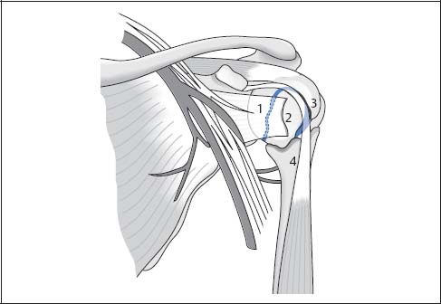
Fig. 2.1  Four-segment classification of the proximal humerus fracture according to Neer
1 Fracture in the region of the anatomical neck
2 Avulsion of the minor tuberosity
3 Avulsion of the major tuberosity
4 Fracture in the region of the surgical neck
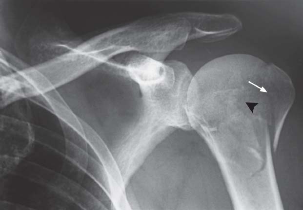
Fig. 2.2  AP projection
Two-segment fracture with avulsion of the major tuberosity (arrow) and fracture through the anatomical neck (black arrowhead). Neer Type II. The absent rotation of the humeral head precludes classification as type III.
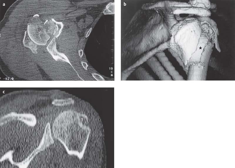
Fig. 2.3 a–c  Proximal humerus fracture, CT
a Axial section at the level of the glenohumeral joint. Detection of multiple, partially displaced fragments. Easy identification and assignment of the osseous fragments on a single section.
b The fracture type, however, can only be determined after 3-D reconstruction (Neer Type III: non-impacted fracture of the surgical neck [asterisk], displaced major tuberosity, angulated humeral head). Oblique posterior view.
c Oblique coronal 2-D reconstruction with documentation of the displaced major tuberosity.
T | Major tuberosity |
Therapeutic Principles
Conservative
About 80% of the fractures of the proximal humerus are one-segment fractures and are amenable to conservative therapy:
 Impacted abduction fractures: Immobilization in the Desault sling until pain relief (about 10 days); subsequent mobility training (swinging movements of both arms)
 Unstable fracture: Immobilization in the Desault sling until pain relief; subsequent application of a hanging cast to extend the fracture (about six weeks)
Surgical
 Two-segment fracture: Closed reduction. Exceptions: displaced avulsion of the major tuberosity and displaced humeral shaft fractures → if unstable after closed reduction, percutaneous fixation with threaded K-wires
 Three-segment fracture: Open reduction with internal fixation, in elderly patients possible prothesis
 Four-segment fracture: Usually requires prosthetic replacement
Diagnostic Evaluation
 (→ Method of choice)
Recommended views
 Standard projections
 Conventional tomography (DD: osteoid osteoma, osteomyelitis, and detection, as well as delineation of free fragments)
Findings
 Fracture line with cortical discontinuity (fracture classification)
 Irreducible fractures
 Instability
 Fat-blood level within the joint capsule with an intra-articular fracture (lipohemarthrosis)

Recommended planes
 Posterior transverse and longitudinal section
 Lateral longitudinal section (coronal plane)
 Dynamic examination
Findings
 Dynamic examination to evaluate dislocated fragments and upward displacement of the major tuberosity (alternative to fluoroscopy)
 Accompanying injury of the rotator cuff and the long bicipital tendon
 Hemarthrosis
 Instabilities
 (→ Supplementary method) (Figs. 2.3, 2.4)
Recommended protocol
 Standard parameters
Findings
 Supplementary method to projectional radiography (modifying the description of the fracture)
 Number, position, and relationship of osseous fragments
 Articular involvement
 Rotatory abnormality (antetorsion angle) and longitudinal difference
 Surgical planning (2-D and 3-D reconstructions)
 Injuries of the labrum and joint capsule (CT arthrography)
 Accompanying injuries
 Instabilities:
– Rotator-cuff injuries
– Bicipital tendon injuries
– Hematomas
– Bursitis
– Joint effusion
 (Fig. 2.5)
Recommended sequences
 STIR sequence
 T1-weighted and T2-weighted TSE sequences (possibly with fat suppression)
Findings
 Accompanying injuries of the rotatory cuff injury and the long bicipital tendon
 Hemarthrosis
 Instabilities
 Osteochondral fractures
 Occult fractures
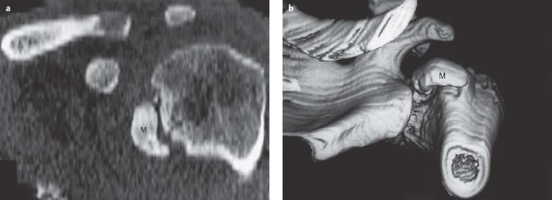
Fig. 2.4 a, b  Proximal humerus fracture, CT
a The oblique coronal 2-D reconstruction demonstrates a displaced avulsion of the major tuberosity.
b The 3-D surface reconstruction performed subsequently facilitates planning the therapeutic approach, without adding any further information.
M | Minor tuberosity |
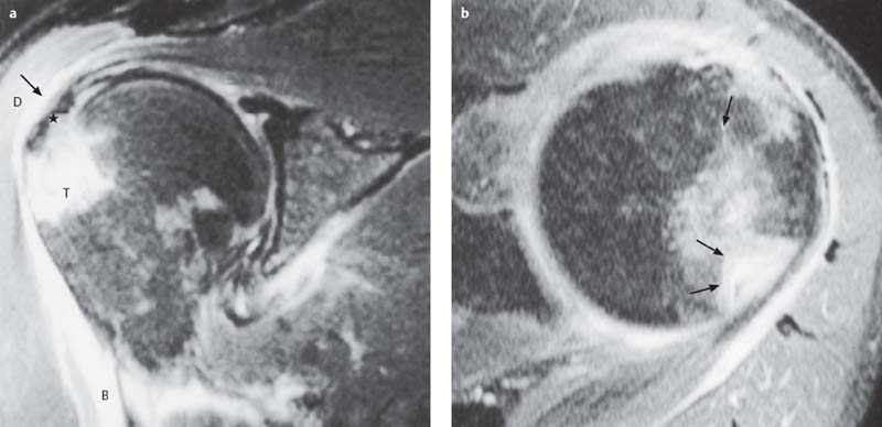
Fig. 2.5 a, b  Proximal humerus fracture, MRI
a T2-weighted oblique coronal section: Intact supraspinatus tendon with discrete hemorrhage at the level of the major tuberosity (asterisk). Avulsion of the major tuberosity with associated bone bruise. Hemorrhage into the subacromial/subdeltoid bursae (arrow). Definite hemorrhage in the deltoid muscle and tendon of the biceps brachii.
b The corresponding axial section (fast low angle shot [FLASH] 2-D) reveals the extent of the avulsion of the major tuberosity to better advantage.
B | Biceps brachii |
D | Deltoid muscle |
T | Major tuberosity |
Clavicular Fracture
Goals of Imaging
 Visualization of the fracture displacement
 Evaluation of the AC joint with lateral fracture
Therapeutic Principles
Conservative
Conservative therapy in 98% of the fractures:
 Knapsack sling (Children: 10 days; adults: three to four weeks), early exercises of the fingers, elbow and shoulder, possibly together with physical therapy, possibly reduction in anesthesia with direct injection into the fracture cleft (axial angulation > 10°, no osseous contact)
Surgical
 Indications: Compound fracture. Neurovascular injuries, pseudarthrosis, pathological fracture, lateral fracture with involvement of the AC joint
 Internal fixation with traction plate and screws (3.5 mm DC plate with six to eight holes)
 Special reconstruction plates
Definition
The clavicular fracture is usually caused by three-point bending that roduces a butterfly fragment in the lateral aspect of the middle third of the clavicle.
Pathology
 Constitutes 10% of all fractures
 Indirect force due to fall on the shoulder or stretched arm
 Location (Fig. 2.6):
– Middle clavicular third = 80%
– Acromial clavicular third = 15%
– Sternal clavicular third = 5%
Classification of the lateral clavicular fracture according to jager and Breitner (1984):
 Type I: Fracture lateral to the coracoclavicular ligament (stable)
 Type II: Fracture in the region of insertion of the coracoclavicular ligament with rupture of the coronoid or trapezoid component
 Type III: Fracture medial to the coracoclavicular ligament (unstable, displaced fragments)
 Type IV: Pseudodislocation in the pediatric age group
Clinical Findings
 Palpable osseous step deformity
 Crepitation
 Shortening of the shoulder girdle due to muscle pull of the pectoralis major
 Restricted mobility
 Accompanying vascular (subclavian artery and vein) and neural injury (brachial plexus)
Diagnostic Evaluation
 (→ Method of choice)
Recommended views
 Views in AP projection
 Projection angulated cranially by 15°
 Projection according to Rockwood
Findings
 Fracture location and classification
 Butterfly fragment in midclavicular fractures
 Posterosuperior displacement of the medial fragment (pull of the sternocleidomastoid and trapezius muscles) in fractures of the medial third
 Inferior, anterior, and medial displacement of the lateral fragment of fractures of the medial third
 Shortening and overriding of the fragments
 Upward displacement of the medial and/or lateral fragment of interligamentous fracture of the acromial third with involvement of the coracoclavicular ligament
 Absent or subtle displacement of fractures of the sternal third
 Rib injuries

Recommended planes
 Posterior axial and longitudinal section
 Lateral coronal section
 Color Doppler sonography
Findings
 Usually no typical finding
 Hypoechoic and hyperechoic structural increase due to fluid accumulation and hematoma
 (Color) Doppler sonography to exclude vascular injuries

Recommended protocol
 Standard parameters
Findings
 Fracture of the medial clavicular third (DD: instability)
 Detection of fragments and their location
 Fracture involvement of the sternoclavicular (SC) joint

Recommended sequences
 STIR sequence
 T1- and T2-weighted TSE sequences (possibly with fat suppression)
 MR angiography for exclusion of vascular injury
Findings
 Usually no typical finding
 Hyperintense signal changes due to soft-tissue trauma in the T2-weighted sequences
 Interruption and hemorrhage of the nerve plexus
 Typical osseous changes as seen in a fracture
 Detection of a vascular injury
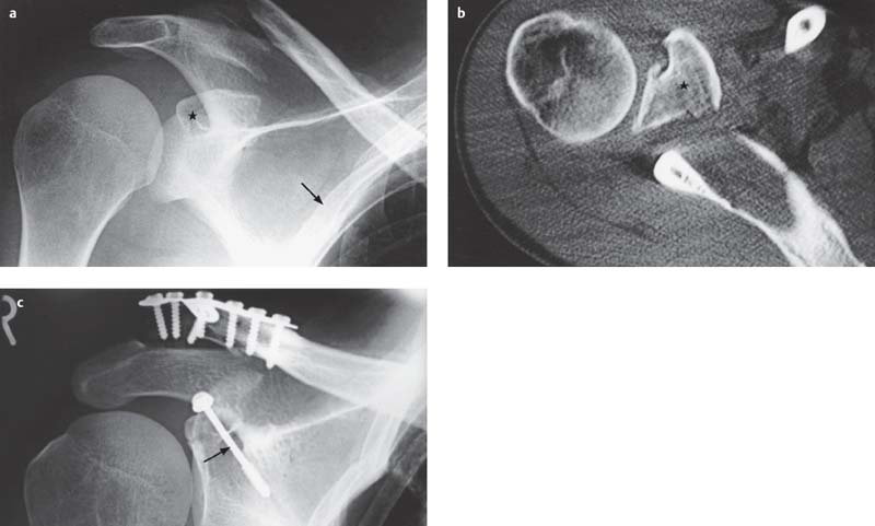
Fig. 2.6 a–c  Clavicular fracture
The AP view demonstrates a clavicular fracture at the most frequent site.
a Detection of an additional fracture dislocation of the coracoid process (asterisk). Associated rib fracture (arrow).
b CT’s ability to visualize free of superimposing structures enables the unequivocal identification of the fracture and the displaced coracoid process (asterisk).
c The postsurgical AP view shows the anatomical alignment of the clavicular fracture by means of a plate and screws. The displaced fracture of the coracoid process has been fixed by a screw (arrow).
Scapular Fracture (Figs. 2.7, 2.8)
Definition
A scapular fracture usually occurs as the result of a direct blow. Isolated scapular fractures are rare.
Pathology
 All types of fractures
 Fracture classification according to anatomical considerations:
– Fracture of the glenoid process
– Fracture of the body of the scapula
– Fracture of the glenoid fossa
– Fracture of the coracoid process
– Fracture of the acromion
 Possibly damage of brachial plexus, axillary nerve, suprascapular artery, suprascapular nerve
Clinical Findings
 Spontaneous pain and pain on movement
 Hematoma formation
 Crepitation
 Restricted motion
Diagnostic Evaluation

Recommended views
 AP views
 Transscapular view
 AP view according to Alexander
Findings
 Localization and classification of fractures
 Fracture assessment only limited

Recommended planes
 Posterior transverse and longitudinal section
 Lateral coronal section
 Color Doppler sonography
Findings
 Usually no typical finding
 Hypoechoic and hyperechoic structural increase due to fluid accumulation and hematoma
 (Color) Doppler sonography to exclude vascular injuries
 (→ Method of choice)
Recommended protocol
 Standard parameters
Findings
 Fracture detection, localization, and classification
 Fracture in the region of the glenoid fossa
 2-D and 3-D reconstruction for surgical planning

Recommended sequences
 STIR sequence
 T1- and T2-weighted TSE sequences (possibly with fat suppression)
 MR angiography for exclusion of vascular injury
Findings
 Usually no typical finding
 Hyperintense signal changes due to soft-tissue trauma in the T2-weighted sequences
 Typical osseous changes as seen in a fracture
 Interruption and hemorrhage of the nerve plexus
 Detection of a vascular injury
Goals of Imaging
 Differentiating the fractures of the scapular body
 Fractures of the coracoid and glenoid processes and intra-articular fracture of glenoid fossa
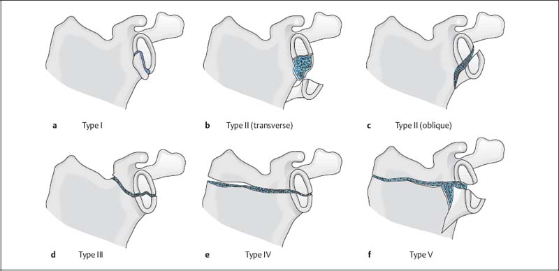
Fig. 2.7 a–f  Classification of scapular fractures according to ldeberg
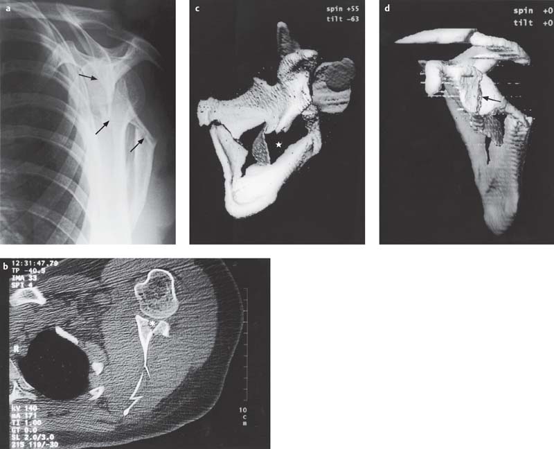
Fig. 2.8 a–d  Scapular fracture type V according to Ideberg
a The Y-view shows a comminuted fracture of the body of the scapula with multiple displaced fragments (arrows).
b Articular involvement can only be suspected on the available conventional radiograph. The axial CT section clearly delineates the comminution of the glenoid fossa (asterisk).
c, d The 3-D reconstructions show the extent of the comminution of the body of the scapula (asterisk) (c) and the articular involvement with corresponding dislocation (d, arrow).
Diagnostic Guidelines for Fractures
1 CR (method of choice for workup of trauma)
Recommended standard projections:
 AP view
 Tangential view of the glenoid fossa
 Axial or axillary view
 Transscapular (Y-)view
 Transthoracic view
Additional special projections:
 Stryker view
 Oblique apical view
 Supraspinatus outlet view
 Stress views
2 US (supplementary investigation)
Indications:
 Exclusion of an injury of the supraspinatus and infraspinatus tendon
 Exclusion of an injury of the long bicipital tendon in the intertubercular groove
 Muscular injury
 Dynamic evaluation for fragment displacement
 Exclusion of instability
 Exclusion of a Hill-Sachs lesion
 Presurgical determination of the antetorsion angle after healing of a malaligned humeral head fracture
 Doppler interrogation to exclude vascular injuries
3a CT (supplementary investigation)
Indications:
 Surgical planning of complex fractures of the proximal humeral head and glenoid fossa (2-D and 3-D reconstructions)
 Exclusion of a fracture of the glenoid fossa (Bankart lesion)
 Presurgical determination of the antetorsion ankle after healing of a malaligned humeral head fracture
 Fracture and dislocation of the SC joint
3b CT arthrography (supplementary investigation)
Indications:
 Exclusion of a rotator-cuff tear
 Evaluation for traumatic instability
 Diagnosis of a SLAP lesion
 Detection of an osteochondral fracture
 MRI has largely superseded the indications of CT arthrography.
4a Conventional MRI (supplementary investigation)
Indications:
 Exclusion of a rotator-cuff tear
 Evaluation for traumatic instability
 Diagnosis of a SLAP lesion
 Exclusion of a bone bruise
 Detection of an osteochondral fracture
 Continuity break and hemorrhage into the nerve plexus
 Detection of a vascular injury
4b Indirect and direct MR arthrography (supplementary investigation)
Indications:
 Improved diagnosis of a labral injury
 Improved diagnosis of a rotator-cuff tear
 Improved diagnosis of an osteochondral fracture
Therapeutic Principles
Conservative
Related posts:
Stay updated, free articles. Join our Telegram channel

Full access? Get Clinical Tree


