65CHAPTER 6
Treatment Planning for SRS and SBRT
Originally, stereotactic radiosurgery (SRS) was performed using different treatment machines than those used for conventional external beam radiation therapy (EBRT). When linac-based radiosurgery was developed in the late 1980s, treatments were delivered with circular collimators and specialized accessories. Accordingly, treatment planning for these systems was also performed on separate, dedicated treatment planning systems. Often, all SRS treatment planning was performed by physicists, whereas dosimetrists handled the majority of EBRT planning.
Although dedicated SRS treatment machines and planning systems still exist today, the majority of radiosurgery, particularly stereotactic body radiation therapy (SBRT), is now performed using conventional linear accelerators, and planned on the same treatment planning systems as those used for three-dimensional (3D) EBRT. On the surface, these treatments may appear no different than conventional EBRT treatments delivered throughout the day. It is important to emphasize to everyone involved in the process of planning and treatment that these treatments are very different from conventional EBRT, and special considerations need to be taken throughout to ensure geometric and dosimetric accuracy.
A process map for treatment planning is shown in Figure 6.1. After import and registration of the image volumes (see Chapter 5), the physician will define the gross tumor volume (GTV). If there is substantial motion of the target, the physician or physicist should analyze four-dimensional (4D) imaging data to define the extent of target motion. From this analysis, an internal target volume (ITV) is generated that includes a margin on the basis of the internal motion of the target. Finally, an additional margin for setup uncertainty is added to generate a planning target volume (PTV).
The physician and physicist or dosimetrist then contour in normal tissue anatomy, and may also add in one or more “tuning” structures to enhance the conformity and gradient of the high-dose volume around the target. The physician specifies target dose and fractionation, and may also specify dose and dose volume limits to organs at risk (OARs) nearby the target.
The physicist or dosimetrist then generates one or more treatment plans for the patient, which may use a variety of beam arrangements including fixed fields, conformal arcs, and intensity-modulated radiation therapy (IMRT) or volumetric-modulated arc therapy (VMAT) delivery. The plans may be generated by forward planning or by optimization on the basis of the dose constraints requested by the physician. A large number of beams or a broad distribution of beams is often used to ensure dose falloff away from the target is as fast as possible.
The physician then reviews the plan(s) to ensure that target coverage, dose gradient, and normal tissue dose sparing are within acceptable limits, and then may suggest revisions to the plan or approve the plan for patient-specific quality assurance (QA) and treatment.
CONTOURING FOR SRS/SBRT
In early SRS planning systems, little or no contouring of tumor targets or normal tissue anatomy was performed for treatment planning. Dose distributions were instead evaluated directly on the patient anatomy visible in the treatment images. Modern treatment planning now typically involves extensive contouring of target volumes, OARs, and tuning structures and detailed evaluation of 3D dose distributions and dose–volume histograms (DVHs).
66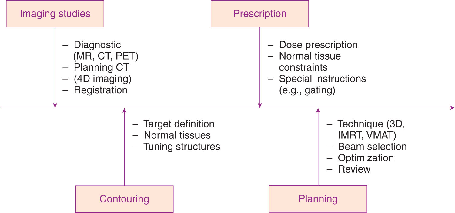
FIGURE 6.1 Process map for SRS/SBRT treatment planning.
IMRT, intensity-modulated radiation therapy; SBRT, stereotactic body radiation therapy; SRS, stereotactic radiosurgery; VMAT, volumetric-modulated arc therapy.
Target Volume Contouring
Target definition in SRS/SBRT is typically performed by the physician only, on the basis of detailed 3D imaging of the patient, often in multiple imaging modalities. Target volumes should follow the recommendations of the International Commission on Radiation Units and Measurements (ICRU; 1, 2), starting with the definition of a GTV. If multiple imaging modalities are used, a separate GTV may be created in each modality, with the final GTV being a sum of the volumes in the two images. Clinical target volumes (CTVs), including a margin around the GTV for microscopic extension of disease, are not typically used in SRS/SBRT planning.
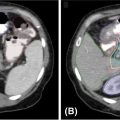
If the target is subject to substantial motion, especially because of respiration, then 4D imaging is often used to define the extent of target motion, which may then be added as a margin around the GTV to produce an ITV. This margin may be defined by detailed analysis of a 4D CT volume, or may be generated directly from an artificially generated image such as a maximum intensity projection (MIP), in which each pixel in the image is replaced by the pixel of the highest density at the pixel location in the entire 4D image data set (Figure 6.2). This image will show the range of motion of lung tumor targets where the tumor is denser than the surrounding lung tissue. This sort of imaging does not work well when imaging tumors are surrounded by tissues of similar or greater density. Enhanced immobilization with abdominal compression of the patient, or other interventions such as tumor tracking or gated delivery, may be used to limit the extent of motion during treatment (see Chapter 4).
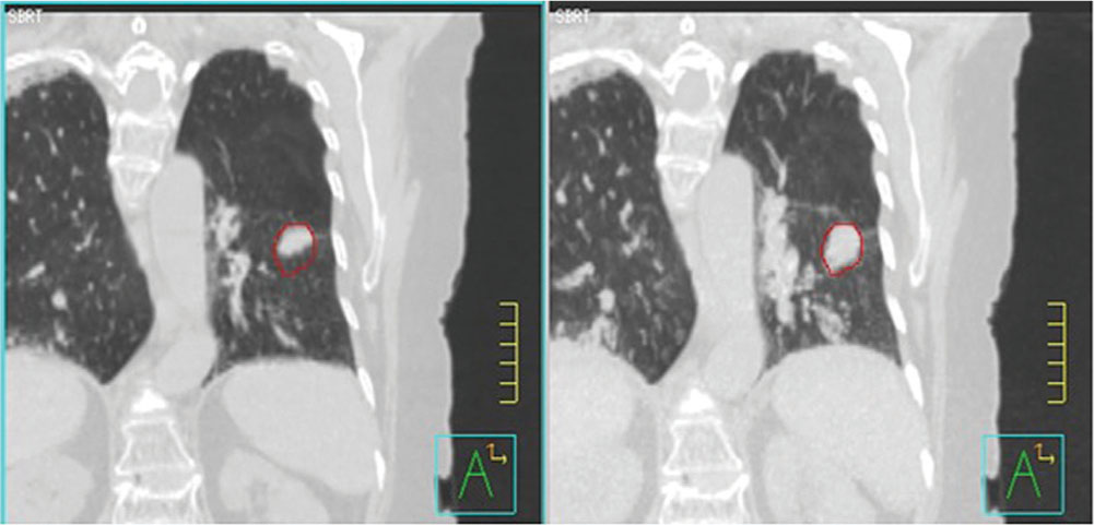
FIGURE 6.2 Left: 4D CT image of lung cancer patient at end expiration. Right: MIP image of lung cancer showing range of target motion.
4D, four-dimensional; MIP, maximum intensity projection.
Finally, an additional margin for setup uncertainty may be added to the GTV or ITV to produce a PTV. SRS/SBRT targets are being treated to very large, ablative fractional doses, so it is important to limit setup uncertainty as much as possible, to limit the size of the PTV. In cranial SRS, in which rigid fixation is often performed, treatment planning is often done with little or no PTV margin. However, there is some geometrical setup uncertainty even in systems with rigid immobilization (3). If treating multiple cranial targets with a single setup isocenter, it may be advisable to add a larger margin of uncertainty to targets further away from the isocenter, where any slight rotation or translation error may result in a larger uncertainty in positioning (4).
In extracranial SRS or SBRT, a PTV margin is typically used to account for the increased uncertainty 67in positioning body targets without rigid fixation. These margins may be asymmetric, particularly if the PTV margin includes motion of the target.
When contouring target volumes by hand, it is important to review the target volume in multiple plane views, including sagittal and coronal views, to confirm that the volume has been consistently defined in three dimensions. When contouring on thin CT slices, it is easy to create “jagged” volumes in three dimensions by slightly altering the position of the contour from slice to slice. These “jagged” volumes are more difficult to conform dose to, because of the finite beam-shaping resolution of multileaf collimators (MLCs) and cones.
Contouring Organs at Risk
Contouring of OARs may be done by the physician or by the physicist or dosimetrist doing the treatment planning, although all contours should be reviewed and approved by the physician. Because inverse planning optimization and plan evaluation are often done on the basis of percent volume of the OAR receiving a specified dose, it is important to contour consistent volumes between patients and between different planners. Detailed guidance on contouring normal tissue anatomy for various treatment sites is provided by the Radiation Therapy Oncology Group (RTOG) in a series of atlases on their website (www.rtog.org).
Uncertainty in positioning because of internal motion or setup error may affect OARs as well as tumor target volumes. If the OAR is close to the target and sparing of the OAR is critical (e.g., spinal cord, brainstem), it is advisable to include a margin around the OAR as well, creating a planning risk volume (PRV). Again, it is important to review OAR contours in three dimensions, particularly for OARs close to or abutting the target volume. “Jagged” OAR contours will make it more difficult to conform dose away from the OAR.
Tuning Structures
Dose conformity to the target volume and dose gradient away from the target volume are critical parameters in SRS/SBRT planning. Special planning structures or “tuning” structures are often used in planning to both promote dose conformity and evaluate it after the plan has been completed.
A ring structure placed around the target volume, either abutting the target or a small offset from the edge of the target, may be used to keep the high-dose volume from spreading beyond the edge of the target (Figure 6.3). Additionally, concentric rings may be added to define the dose gradient around the target. For example, for small, cranial targets, the dose in an SRS plan can be expected to fall to 50% of the prescribed dose within a distance of about 5 mm from the edge of the target. A ring placed 5 mm from the target edge may therefore be used as an optimization structure with a limit of 50% of the prescribed dose to force this kind of gradient. Clark et al. (5) describe a system of multiple, 0.5-cm-thick concentric rings around cranial targets to optimize dose conformity and dose gradient in VMAT planning.
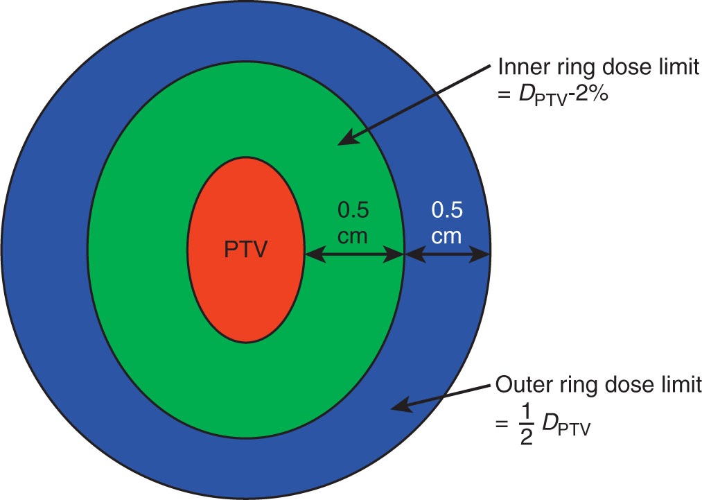
FIGURE 6.3 Ring structures used in SRS treatment planning.
PTV, planning target volume; SRS, stereotactic radiosurgery.
Rings used in this kind of planning tend to make the dose falloff uniform in all directions from the edge of the target. In situations in which there are critical OARs immediately adjacent to the target, it may be more desirable to increase the dose gradient in a single direction. In these cases, ring structures may still be used, but should be given lower priority during optimization.
In extracranial treatments, with larger target volumes, the dose falloff will be more gradual, and dependent on target volume. Several RTOG protocols recommend limits on the maximum dose anywhere 2 cm from the edge of the target; a ring at this location may be used to limit this dose in optimization and evaluate the dose in the final plan.
In many cases, dose limits to adjacent OARs may limit how well the target volume may be covered by the prescribed dose. In these cases, partial volumes of the target or the OARs may be created to help in optimizing the plan. For example, if a paraspinal mass is being treated to 18 Gy, but the mass abuts the spinal cord (limit = 10 Gy), then an optimization target may be drawn containing only that part of the target at least 3 mm from the edge 68of the cord (Figure 6.4). This optimization target may be planned and treated to full dose while safely respecting the dose limits to the cord.
Another situation in which partial volumes may be used is the case in which a large organ abuts an SRS target, but only a very small portion of the organ will receive significant dose (e.g., the small bowel adjacent to a pancreatic cancer). In this case, optimizing the dose to the entire bowel may not effectively limit its dose, because the high-dose region may represent only a small percentage of the total volume of the bowel. A partial volume consisting of the bowel within 2 cm of the edge of the target will be much more effective in limiting the bowel dose near the target.
Nonpatient Structures
It is important to include all nonpatient structures (couch, mask, immobilization frame) in the treatment plan to correctly account for any attenuating effects they may have on the beam or any buildup effect they may have to the skin of the patient.
Hoppe et al. (6) reported a lung SBRT case in which the initial dose calculation, which did not include any couch structures, indicated a peak dose to the skin of 50% of the prescribed target dose. The patient sustained a Grade IV skin reaction after treatment. When the effect of the treatment couch was added to the dose calculation, it revealed that the true skin dose was closer to 90% of the prescribed dose.
FIELD SETUP—CRANIAL SRS
In traditional cranial SRS, a small number of standard beam arrangements could be used for almost all plans (e.g., the fixed beam directions defined by the openings in a Gamma Knife helmet). Small variations could be made to deliver a more rapid dose gradient in one direction or another. The use of either the Gamma Knife or cone-based linac SRS results in roughly spherical dose volumes or “shots,” and larger or more irregular-shaped targets would then be treated by adding together multiple shots with different isocenters.
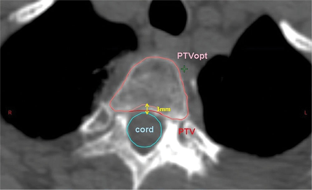
FIGURE 6.4 Optimization PTV for paraspinal tumor. PTV is cropped 3 mm away from the spinal cord to reduce dose to the cord.
PTV, planning target volume.
Similarly, in treatment delivery with the Accuray CyberKnife, the beams used for treatment all lie along a fixed path of the robot gantry, designed to allow the robot to move without interfering with the patient. The robot travels to every fixed position or “node” for every patient, but delivers beam only from a subset of these positions, determined during plan optimization.
The development of MLC-based linac SRS now allows a larger variety of treatment delivery options: fixed MLC fields, conformal arcs, IMRT, or VMAT. The last two options also allow for inverse planning, in which plans are optimized on the basis of specified dose goals for the target volume and dose limits for the adjacent OARs. Inverse planning allows better dose conformity around irregular target volumes, and better ability to conform dose away from specific OARs near the target.
The greater clearance of the linac gantry around the cranium allows for the greater use of noncoplanar beams, which are commonly used in cranial SRS. Noncoplanar geometries allow faster dose falloff in all directions than coplanar beam arrangements. Clark et al. have examined a series of standard noncoplanar geometries for VMAT planning for cranial SRS using one, two, three, and four arcs (5) (Figure 6.5).
Noncoplanar beams may also be used from fixed beam directions. Having too many unique couch angles, however, will require a much longer time to set up and treat the patient. At UPMC Hillman Cancer Center, the emphasis is to limit plans to no more than three to four unique couch angles.
FIELD SETUP—EXTRACRANIAL SRS/SBRT
In extracranial SRS/SBRT, the number of beam directions that may be used from a conventional linac is more limited because of the location of the target and the risk of collision between the gantry and the patient’s body or the treatment couch. Coplanar beam arrangements are faster and simpler to set up, but this requires all of the dose falloff to occur in a single, axial plane. Noncoplanar beams can make the dose falloff more uniform in all directions, and reduce integral dose to the patient, but may make patient setup more difficult and time-consuming. In addition, couch rotation tends to be the least accurate motion in many linacs, and may introduce additional uncertainty in patient setup unless this is carefully checked.
69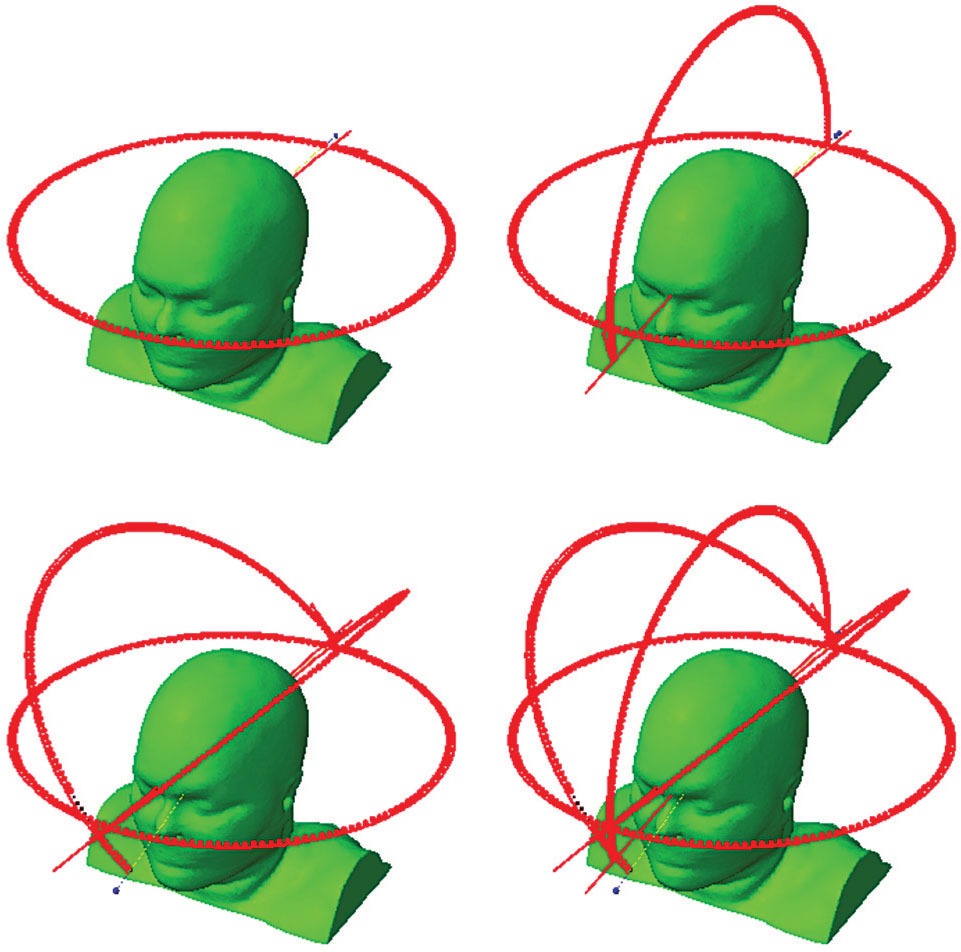
FIGURE 6.5 Arc geometries for one-, two-, three-, or four-arc VMAT plans for cranial SRS planning.
SRS, stereotactic radiosurgery; VMAT, volumetric-modulated arc therapy.
Source: Clark GM, Popple RA, Prendergast BM, et al. Plan quality and treatment planning technique for single isocenter cranial radiosurgery with volumetric modulated arc therapy. Pract Radiat Oncol. 2012;2(4):306–313. doi: 10.1016/j.prro.2011.12.003
For unilateral target volumes (peripheral lung lesions, liver), targets may be treated with partial VMAT arcs or from fixed beam directions from the ipsilateral side. Small rotations of the treatment couch (up to about ±20°) may be feasible for many patients, depending on target location and patient size. There is more flexibility when adding noncoplanar beams with fixed beam directions than with continuous arcs, but care must be taken to check clearance, particularly if using automatic field sequencing. A dry run of all beams in the order in which they will be treated is essential before treatment proceeds.
For central target volumes (spine, pancreas), there is very little clearance for noncoplanar beams, particularly arcs, and these cases are generally planned with coplanar field arrangements. Again, if noncoplanar fields are needed for an optimal plan, it is easier to use these with fixed beam directions than with continuous arcs.
When using fixed or conformal beams or arcs, the MLC field border should be placed close to the edge of the target volume. This is in contrast to conventional radiation therapy, where the field border is placed at a sufficient distance from the edge of the target to achieve relatively uniform dose coverage of the target. If the field margin is smaller than the beam penumbra, this will result in inhomogeneous dose to the target, with maximum dose 125% or more of the prescription dose, but much faster dose falloff away from the target (7).
In either cranial SRS or extracranial SBRT, it is important to use a sufficient number of beams, or spread of degrees of arc, to improve dose falloff away from the target and to ensure that the dose at the patient’s skin surface is not excessive. At least eight fixed beams, or at least 200° of arc, should be used in SRS/SBRT planning.
DOSE CALCULATION FOR SRS/SBRT
In the early SRS treatment planning systems, a simplified dose model was often used to calculate dose, using a simple, pencil beam calculation with all tissue assumed to have a density equal to that of water density. Although this gave acceptable results in most parts of the cranium, this sort of calculation is not sufficient to accurately characterize SRS/SBRT plan doses throughout the body. The dose calculation performed for SRS/SBRT must be of sufficient geometrical and dosimetric accuracy to determine dose to the treatment volume to within 1 mm/5% agreement for cranial SRS, and within 2 mm/5% agreement in body SBRT.
Dose calculation in SRS/SBRT is complicated by the difficulty of taking accurate commissioning measurements for very small fields. Errors as large as 40% have been reported when measuring fields smaller than 1 × 1 cm2 with inappropriate detectors, which have led to multiple misadministrations in SRS delivery (8).
Also, most treatment planning system algorithms are created and optimized for generalized radiation therapy, and may not be optimal for very small fields. Some algorithms (e.g., Varian Eclipse AAA) do not use any measured dose information for fields smaller than 3 × 3 cm2, although they may still be used to calculate dose for smaller fields.
When starting an SRS/SBRT program, therefore, it is necessary to test the current photon dose algorithm for accuracy at small-field dose calculation. It may be necessary to recommission the dose model with additional, small-field data. Bedford et al. have reported improved results by creating separate dose models for small fields (9).
The effects of tissue heterogeneities on very small fields are also larger than those seen with larger fields (10). In low-density lung tissue, the 70loss of lateral scatter equilibrium results in very large buildup effects at lung–soft tissue interfaces. Accurate, high-resolution calculations are required to characterize dose in these areas correctly. Older, pencil-beam–type algorithms are not appropriate for SBRT, because these can result in dose errors as large as 40% in lower density lung tissue (11).
The resolution of the dose grid can also have an effect on the absolute dose reported by some algorithms, particularly in highly modulated IMRT/VMAT plans. Ong et al. (12) have reported that the absolute dose calculated by the Varian Eclipse AAA algorithm can differ by as much as 10% between 1 and 2.5 mm dose grid resolution. We have seen absolute dose differences as much as 4% in AAA-calculated plans between 1.0 and 1.25 mm dose grid resolution (Travis McCaw, personal communication, 2016).
EFFECT OF MLC LEAF WIDTH ON PLAN QUALITY
Several different models of MLC are available for field shaping from different vendors. The initial MLCs used in IMRT/VMAT used 1.0-cm leaves, and so were not capable of field shaping for very small targets. Newer linear accelerators use MLCs with leaf widths between 0.25 and 0.5 cm. Wu et al. have compared plan results between 0.25- and 0.5-cm leaves for various SRS targets in the cranium, liver, and spine, and reported improvements in dose coverage, conformity, and sparing of OARs with the smaller MLC leaves (13). The improvements were larger for the smaller targets in the cranium, and for the more irregular target shapes in the spinal lesions. For larger, regularly shaped lesions in the liver, the gains in target coverage and conformity were not significant.
TREATMENT PLAN OPTIMIZATION FOR SRS/SBRT
In early SRS treatment planning systems, plan optimization was performed using manual trial and error iteration, with the human planner making small adjustments in treatment cone size or isocenter position to improve target coverage or avoidance of nearby structures. Many automated optimization routines are now available, some of them specifically designed for special applications, such as radiosurgery of multiple brain metastases (Brainlab ElementsTM). When optimizing plans for SRS/SBRT, it is important to keep in mind the goals of this kind of therapy, and how they differ from conventional fractionated radiation therapy.
The biggest difference in SRS/SBRT is the emphasis on dose conformity and dose gradient over dose uniformity in the target. Dose optimization constraints should therefore be set that allow for substantial dose heterogeneity, at least 10% to 15%, in the target volume. Emphasizing dose homogeneity in the target volume will cause the high-dose volume to become less conformal to the edge of the target.
In planning systems that allow variable resolution of dose calculation during optimization, it is important to use the highest dose resolution available during optimization of SRS plans, or the final plan result may not turn out to be optimal. High-resolution calculations may result in very long optimization times. Some planning systems also allow for variable resolution between different structures in the plan—in this case, it may be possible to improve optimization time by sampling only the target and nearby OARs (or even partial OAR volumes near the target) to high resolution, and using lower dose grid resolution away from the target.
It may also be possible to save time during dose calculation by restricting the dose grid to a smaller volume around the target. However, it is very important to calculate dose to the entire patient volume in the final calculation (or, at least, the entire patient volume in which treatment beams pass) to ensure that there are not hot spots on the patient’s skin near the entrance or exit of beams well away from the target.
When performing inverse planning for IMRT/VMAT, a separate dose calculation algorithm is often used for optimization to complete optimization faster. These algorithms are often based on older, pencil-beam–type models that underestimate the effects of the loss of lateral scatter. Plans optimized with these algorithms may be suboptimal after the final dose calculation, particularly in lung SBRT. Several planning systems allow an “intermediate”-dose calculation, in which the full-dose calculation algorithm is used part-way through optimization so that the final plan is much closer to the optimized solution. Intermediate-dose calculations should be used for all optimized SRS/SBRT plans that use a pencil-beam model for optimization.
Most optimization routines are based on a single “cost function,” which attempts to minimize the difference between the requested dose goals and the final plan. When conflicts exist between the target coverage and dose limits to the adjacent OAR, there is often a trade-off between these goals, weighted by the priority 71assigned to each goal. If there are hard constraints on dose to a particular OAR, it may be necessary to enter dose limits that are substantially lower than the true constraint, to meet the final dose limit to the OAR. Again, these dose goals may be made more effective, particularly for larger OARs, by creating a subvolume of the OAR adjacent to the target.
TREATMENT PLAN EVALUATION FOR SRS/SBRT
As with any 3D-conformal treatment plan, the dose distribution in SRS/SBRT plans should be carefully reviewed in both the CT image volume and in the DVH display, to ensure that the dose goals to the target(s) and OARs have been met. In “parallel” OARs (e.g., lung, liver), there is redundancy of function throughout the organ, and toxicity is related to total volume of the organ receiving a high dose. In “serial” OARs (e.g., spinal cord), toxicity is related to the peak dose received by a small volume of the organ, or the dose that transects the entire circumference of an organ at one location. Careful review of both the DVH (for parallel organs) and the dose displayed on the CT image volume (for serial organs) must be done to ensure the SRS/SBRT plans will be safe to deliver.
Detailed discussion of SRS/SBRT OAR tolerance doses for different treatment sites can be found in the later chapters of this book as well as in various RTOG protocols, and in the table by Timmerman presented in the American Association of Physicists in Medicine (AAPM) TG-101 (11). In addition, care should be taken to ensure that there are no excessive hot spots in nonspecified tissue in the body, particularly skin dose where beams enter or exit the body.
There are also standard indices that have been used to assess dose conformity and dose gradient in SRS/SBRT plans. If the prescribed dose = 100%, then the conformity index (CI) is defined as the ratio of the volume of tissue at the prescribed dose (V100%) divided by the volume of the target (VPTV). Ideally, the prescribed dose should cover the target exactly and nothing else, leading to a CI = 1.0. One limitation of this index is that it does not address how well the target is covered by the prescribed dose; a plan could have very poor target coverage with substantial high dose outside the target, and still have a CI equal to or less than 1.0. A new conformity index (nCi) has been defined for this reason as the volume of tissue at the prescribed dose divided by the volume of the target covered by the prescribed dose (VPTV100%).
Dose gradient may also be defined in several ways. RTOG protocols include a gradient index defined as the ratio of the 50% isodose volume over the 100% (prescribed) isodose volume. This ratio is highly dependent on target size, and so the protocols set their acceptance criteria for this index on the basis of target volume. One planning system defines a different gradient index by calculating an “average” distance from the 100% to the 50% isodose line around the target. This is calculated by converting V100% and V50% into spheres with the same volume, and calculating the difference between the radii of the two spheres.
REFERENCES
1. ICRU Report 62, Prescribing, Recording and Reporting Photon Beam Therapy (Supplement to ICRU Report 50). 1999.
2. ICRU Report 50, Prescribing, Recording and Reporting Photon Beam Therapy. 1994.
3. Brezovich IA, Wu X, Duan J, et al. End-to-end test of spatial accuracy in Gamma Knife treatments for trigeminal neuralgia. Med Phys. 2014;41(11):111703. doi: 10.1118/1.4896819
4. Jang S, Huq M. Dosimetric impact of rotational error on multiple-target intensity-modulated radiosurgery (IMRS) with single-isocenter. Med Phys. 2014;41:329. doi: 10.1118/1.4888783
5. Clark GM, Popple RA, Prendergast BM, et al. Plan quality and treatment planning technique for single isocenter cranial radiosurgery with volumetric modulated arc therapy. Pract Radiat Oncol. 2012;2(4):306-313. doi: 10.1016/j.prro.2011.12.003
6. Hoppe BS, Laser B, Kowalski AV, et al. Acute skin toxicity following stereotactic body radiation therapy for stage I non-small-cell lung cancer: who’s at risk? Int J Radiat Oncol Biol Phys. 2008;72(5):1283-1286. doi: 10.1016/j.ijrobp.2008.08.036
7. Hong LX, Garg M, Lasala P, et al. Experience of micromultileaf collimator linear accelerator based single fraction stereotactic radiosurgery: tumor dose inhomogeneity, conformity, and dose fall off. Med Phys. 2011;38(3):1239-1247. doi: 10.1118/1.3549764
8. Das IJ, Ding GX, Ahnesjö A. Small fields: nonequilibrium radiation dosimetry. Med Phys. 2008;35(1):206-215. doi: 10.1118/1.2815356
9. Bedford JL, Childs PJ, Nordmark Hansen V, et al. Commissioning and quality assurance of the Pinnacle(3) radiotherapy treatment planning system for external beam photons. Br J Radiol. 2003;76:163-176. doi: 10.1259/bjr/42085182
10. da Rosa LAR, Cardoso SC, Campos LT, et al. Percentage depth dose evaluation in heterogeneous media using thermoluminescent dosimetry. J Appl Clin Med Phys. 2010;11(1):117-127. doi: 10.1120/jacmp.v11i1.2947
11. Benedict SH, Yenice KM, Followill D, et al. Stereotactic body radiation therapy: the report of AAPM Task Group 101. Med Phys. 2010;37(8):4078–4101. doi: 10.1118/1.3438081
12. Ong CL, Cuijpers JP, Senan S, et al. Impact of the calculation resolution of AAA for small fields and RapidArc treatment plans. Med Phys. 2011;38(8):4471-4479. doi: 10.1118/1.3605468
13. Wu QJ, Wang Z, Kirkpatrick JP, et al. Impact of collimator leaf width and treatment technique on stereotactic radiosurgery and radiotherapy plans for intra- and extracranial lesions. Radiat Oncol. 2009;4(1):3. doi: 10.1186/1748-717X-4-372
Related posts:


Stay updated, free articles. Join our Telegram channel

Full access? Get Clinical Tree


