Fig. 2.1
Schematic drawing of IJV and its segments. (1) J1 or proximal segment, focused to the valve system. (2) J2 or intermediate segment. (3) J3 or distal segment, where the common facial vein ends into the IJV

Fig. 2.2
IJV in transverse scan at the level of the valve leaflets (J1) in B-mode. The valve system is well identifiable with two cusps in an intermediate position between the complete opening and the closure. The valve leaflets (see the asterisks) seem as hyperechoic curve and tiny lines coming from one side to the other of the vessel wall within the lumen. Movie 2.1 shows a dynamic example of the leaflets’ movement
Fig. 2.3
Longitudinal scan of the IJV at the level of the valve system (J1) in B-mode. Also in this case are well evident the valve leaflets as two slightly hyperechoic lines into the IJV lumen, stopped in an intermediate position during the opening–closing cycle. The valve cusps define the valve sinuses (white asterisks) at the IJV bulb. Movie 2.2 shows a dynamically view of the leaflets movement
Fig. 2.4
Longitudinal scan of IJV at the valve level (J1) in B-mode, focusing on a particular aspect. In the left side a, the valve is totally open and has two well-identifiable separate leaflets; in the right side b, the valve is close and the leaflets are adherent each to other into the IJV lumen near the midline. Pictures are oriented leaving the head of the examined subject on the left end and the heart on the right end
Fig. 2.5
Longitudinal scan of IJV at the valve level (J1) in color mode; the subject is the same as in Fig. 2.4. In the left side of the picture, there is the schematic drawing of the IJV with the level of insonation. In the right side, the two magnified pictures show the color-coded signal of blood flowing through the open valve (top image) and the stopped color-coded signal of blood flow because of the valve closure. The pictures are oriented as detailed in the caption of the Fig. 2.4
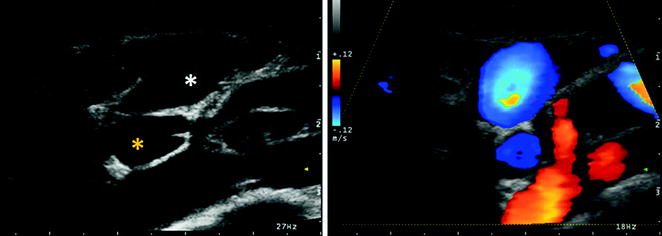
Fig. 2.6
Transverse scan of J1 IJV in B-mode (in the left side) and in color mode (in the right side). It is often possible to simultaneously visualize the IJV and VV valve system, as in present picture is exemplified. IJV (white asterisk) and VV (yellow asterisk) are imaged in the same picture at the level of the valve system of both veins, See also the correspondent Movies 2.3 and 2.4
2.1 Jugular Veins
IJV is the vein of greater size in the cervical region and is considered the main cerebral venous outflow route, particularly in the supine position. The cerebral venous flow goes mainly from the superficial and deep venous system to the transverse sinus (TS) which in its turn continues in the sigmoid sinus (SyS), which drains into the IJV. The IJV joins the subclavian vein (SV) to form the BCV. The confluence of the two brachiocephalic veins gives rise to the superior vena cava (SVC), which drains the cerebral venous blood in the right atrium.
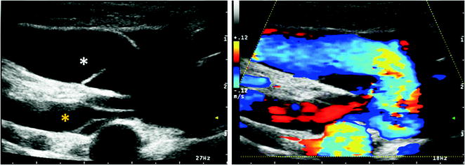
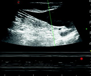
Fig. 2.7
Longitudinal scan of J1 IJV in B-mode (in the left side) and in color mode (in the right side). As in the Fig. 2.6, it is often possible to simultaneously visualize the IJV and VV valve system, as in present picture is exemplified in longitudinal scan. IJV (white asterisk) and VV (yellow asterisk) are imaged at the valve level. The valve system seems composed from two leaflets for both veins. See also the correspondent Movie 2.5
Fig. 2.8
Longitudinal scan of IJV at the valve level (J1) in M-mode. Another way of evaluate the valve leaflets movement is by using M-mode as echocardiographic evaluation of valve function. The M-mode allows to evaluate the movement of the structures at different depth levels along the sampling line (M-line). The M-line in the picture is green, and, in the lower part of the image, the asterisk indicates the line correspondent to the cycles of movement of one IJV leaflet. See also the Movie 2.6
Fig. 2.9
Transverse scan of IJV at the level of the thyroid gland (J2) in B-mode (upper part of the picture) and in color mode (lower part of the picture). The red asterisk indicates the thyroid gland, the white one the common carotid artery, and the yellow one indicates the IJV
Fig. 2.10
Longitudinal scan of IJV at the level of the intermediate segment (J2), in B-mode (upper part of the picture) and in color mode (lower part of the picture). The white asterisk indicates the CCA and the yellow one the IJV, and upon the IJV course, the suprafacial muscular planes of the neck are identifiable. In this example, IJV is parallel to the CCA within the same sheath and both vessels are visible in the same scanning plane but with opposite blood flow direction, as shown in color mode. See also the correspondent Movie 2.7
Fig. 2.11
a Longitudinal scan of IJV at the level of the intermediate segment (J2) in M-mode. By using this scanning mode, it is possible to evaluate the width of the movement of expansion–contraction of the IJV in comparison with the movements of the CCA, as reference for the heart cycle. It is noticeable that the variations in the IJV diameter are different in each heart cycle because of the superimposed effect of the breath cycle. It is sometimes difficult to differentiate one component from the other one, especially in some situations, as in the presence of IJV valve incontinence or pulmonary hypertension, where the breath-dependent variations can be much more accentuated. b This variability is expressed in the Doppler waveform that is affected by the same components, as in this example
Fig. 2.12
Transverse scan of IJV at the level of the distal segment (J3) in B-mode and color mode. From up to bottom: (1) image in B-mode with manual tracking of J3 IJV CSA; on the left side (white asterisk), there are the CCA and the external carotid artery (ECA), slightly upon the carotid bifurcation, and besides there is the common facial vein (see also the Movie 2.8). (2) Image in color mode of the same structures with the opposite direction of blood flow in arteries and veins showed by Doppler waveform. (3) Doppler waveform of the common facial vein (left side) and J3 IJV (right side)
Fig. 2.13
Longitudinal scan of IJV at the level of the distal segment (J3). From up to bottom: (1) B-mode scan with J3 IJV (yellow asterisk) and carotid axis (white asterisk). (2) Image in color mode of the same structures, with the identification of the opposite direction between arteries and veins in the Doppler waveform (see also Movie 2.9). (3) J3 IJV Doppler waveform
Fig. 2.14
Longitudinal scan of IJV at the level of J1, J2, and J3 in color mode and Doppler mode. From top to bottom, J1, J2, and J3 IJV are imaged; the variation of the Doppler waveform is showed, being similar to the one of central veins in J1–J2 segments, nearer to the right atrium, and partially different in the J3 segment, more distant from the right atrium
Fig. 2.15
Schematic drawing of the venous plexus of the VA at the V1 and V2 levels; VV is outlined in blue, and the vertebral artery is outlined in red; the gray boxes correspond to the shadows of the vertebral bones in the ultrasound image
The IJV therefore begins at the level of the jugular foramen, after the junction of the inferior petrosal sinus (IPS) with the SyS, as a direct continuation of the latter. At this level, there is a slight expansion, called jugular bulb or gulf, which cannot be explored by ultrasound, and which continues relying on the anterior surface of the transverse process of the atlas [6]. The interaction between these two structures may obstruct the jugular venous outflow in some cases evidenced by neurosurgery. However, not even this segment can be investigated by ultrasound, while the next segment, at the level of epistropheus or C2, becomes explorable. In this segment, the relationships of contiguity of the IJV with the carotid axis are easily recognizable. The most common course of IJV is slightly anterior and lateral compared to the internal carotid artery (ICA), with a distance of about 1 mm from it in 69.5 % of examined cases. Variations in the anatomy of the IJV and its correlation to CCA are frequent [7]. The subsequent course of the IJV maintains this relationship with CCA, passing under the anterior edge of the sternocleidomastoid muscle to join the SV and converge into the BCV [8].
In a study performed with computed tomography angiography (CTA) aimed to evaluate the IJV anatomy and its relationship to the carotid artery, out of 176 IJV examined both from the right and from the left side compared to the CCA, 85.2 % of IJV were in a lateral position, 12.5 % in the anterior position, 1.1 % in the medial position, and 1.1 % in the posterior position [7]. Furthermore, in an ultrasonic study designed to evaluate the degree of overlap between the IJV and CCA in the position of the head suitable for IJV cannulation, in over 1,000 veins, the IJV covers even if only partially the CCA in 54 % of patients, predisposing them to the accidental puncture of the carotid artery [9]. The variability may be even greater if you consider the effect of the rotation of the head; in fact, the overlap between IJV and CCA increases passing from the neutral position of the head to a rightward rotation (23.3 vs. 39.2 %) and to a leftward one (35.3 vs. 52.8 %), so that the incidence of lateral positioning of the IJV compared to the CCA is significantly reduced with the rotation of the head (40 vs. 21 % at right, 26.5 vs. 10.5 % at left). The right side appears, however, associated with a minor overlap, whatever the position of the head [10].
Fig. 2.16
Venous plexus of the vertebral artery at the level of V1 and proximal V2 segments in B-mode. The vertebral artery is indicated by the white asterisk and the venous plexus surrounding it by the yellow asterisk. The Movie 2.10 shows the dynamic relation between these structures
Fig. 2.17
VA venous plexus at the level of V1 and proximal V2 segments in color mode. The opposite color-coded signal of artery and vein corresponds to the different flow direction. It is evident the plexiform aspect of the vertebral venous outflow, surrounding the VA, and the confluence of at least one deep cervical branch (green asterisk), frequently found at this level, where the main trunk of the VV collects the flow from plexi and deep cervical veins before to join the SV. See Movie 2.11 about the relation between arteries and veins
Fig. 2.18
Venous plexus of the VA at the level of V1 and proximal V2 segments in color mode and Doppler mode. In the examples, two features are represented: (1) the morphological variability of the plexus with more (top image) or less (bottom image) evident venous network and deep cervical veins confluence. (2) The Doppler waveform variability, more (bottom image) or less (top image) similar to the one of central veins
Fig. 2.19
VA venous plexus at the V1 and proximal V2 levels in color mode and Doppler mode. The entrance point of two deep cervical veins is identified and the Doppler waveform sampled, showing the same variability as IJV one depending on heart and breath cycles
An important and well-studied element of the IJV is its valve apparatus, located near the confluence with the SV, and present in 86–93 % of the veins in autopsy case studies [11].
From the ultrasound point of view, it is therefore possible to divide the IJV into three different segments:
a rostral segment or J3, bounded below by the carotid bifurcation and corresponding to the IJV segment before receiving the confluence of the common facial vein.
an intermediate segment or J2, between the carotid bifurcation and the supravalvular plan,
a lower segment or J1, consisting of the valve plane and of the dilation immediately supravalvular.
Morphological anatomical abnormalities of IJV are considered rare; for example, duplication would have a ratio of 4/1000 unilateral cervical dissections [12].
2.2 Internal Jugular Vein Valves
The high-resolution ultrasound examination revealed the presence of a valve in one or both veins in 87 % of cases in the series of Lepori et al. [13] and in 72 % in the series of Macchi and Catini [14]; the series of Darge et al. [15] in a population of children and young adults has found instead a prevalence of 96 %. In autoptic studies on adults, the 86–88 % of the examined subjects had a valve [16, 17]. Gender differences in the prevalence of the valvular apparatus of the IJV are not reported, and in the subjects with unilateral valve, it is more commonly located to the right side.
Related posts:
Stay updated, free articles. Join our Telegram channel

Full access? Get Clinical Tree


