Fig. 1.
Setup for re-dispersing lipid vesicles consists of an (a) Branson ultrasonic water bath cleaner, and (b) Eppendorf microfuge tube in a glass scintillation vial. The Eppendorf tube is tightly capped and sealed with 1 parafilm “M” laboratory film; 2 labeled; 3 placed in vial with water at indicated level; and sonicated until 4 vesicle solution clears.
19.
Kimwipes.
20.
Refrigerate at 4°C for incubation steps.
2.7 MFP-3D BIO AFM and Accessories (See Note 5; Fig. 2)
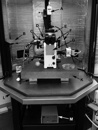
Fig. 2.
MFP-3D BIO AFM setup as configured in our laboratory for macromolecular and cell biology applications includes (a) Top View camera for probe viewing and alignment; (b) MFP-3D BIO stainless steel platform for mounting cantilever holder on head; (c) optical (x,y) alignment controls which move the entire base plate to translate the cantilever and specimen to field of view with bottom view cameras via objectives; (d) x,y scanner; (e) MFP-3D BIO Head; (f) sample (x,y) alignment controls which move the sample relative to the cantilever; (g) IX71 Olympus inverted optical microscope; (h) Hamamatsu video camera for highest resolution viewing and recording; (i) Composite camera for lower resolution viewing and image capture; (j) isolation module (×2); (k) granite slab; (l) TMC BCH-45 acoustic enclosure platform; and (m) vibration isolation electronics controller. The ARC2 with Hamster, Fiber-Lite, Hamamatsu, X-cite, and heater controllers are not shown.
1.
BCH-45 Acoustic Hood Enclosure by TMC, Wakefield, MA.
2.
AVI-350/LP Active Vibration Isolation System (see Note 6).
3.
MFP-3D AFM Head Platform.
4.
MFP-3D AFM Head (Fig. 3; see Note 7).
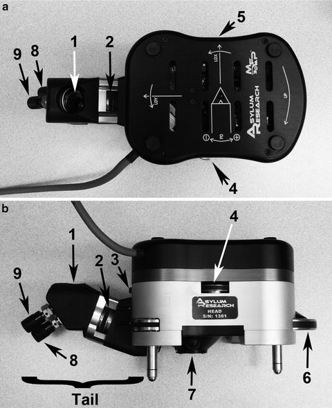
Fig. 3.
Controls on the MFP-3D head in the (a) top view and (b) side view are: 1 “tail” mirror; 2 top view camera focus wheel; 3 LDY adjustment wheel which moves laser across the cantilever; 4 deflection (PD: PhotoDiode) positioning wheel which centers the reflected laser beam on the head’s photo detector; 5 LDX adjustment wheel which moves laser along the cantilever; 6 engagement (front leg) thumbwheel which raises and lowers the head and cantilever away from and towards the sample; 7 underside location of head where cantilever holder is attached; and 8 and 9 x,y mirror movement knobs which adjust view of cantilever probe in the AR “Live Video” panel.
5.
XY Scanner (Fig. 4; see Note 8).
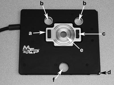
Fig. 4.
The uppermost component of the Bio baseplate is the x,y scanner shown here with (e) a substrate secured with two (c) magnets. The x,y scanner platform has (a) a scanner “top plate” which moves the sample on the secured substrate; (b) two back leg holes; (d) spring post for securing the scanner to the baseplate; and (f) a front leg hole. The holes accommodate the head’s three legs to rest directly on the baseplate for appropriate position orientation.
6.
Adjustable Metal Base Plate.
7.
IX71 Olympus Inverted Optical Microscope with ×10, ×40, and oil ×60 objectives (see Note 9).
8.
Optical filter cubes for fluorescence.
9.
Video Cameras (see Note 10).
10.
Fiber Lite.
11.
Dell Precision T3500 Central Processing Unit with Dual Monitors.
12.
Igor Software by Wavemetrics (see Note 11).
13.
Asylum Research AFM Operating Software Modules and SmartStart Bus Recognition.
14.
ARC2 SPM Electronics Controller with integrated Hamster.
15.
AR Cantilever Holders (Standard or i-Drive).
16.
AR Cantilever Holder Stand.
17.
Low Power Binocular Dissection Microscope and Light Source(s).
18.
Tweezers and “Philips” screwdriver (for standard holder) or “Straight” screwdriver (for i-drive holder).
19.
Duster (moisture-free lint and dust remover).
20.
Laboratory Squeeze Bottle with Fine-tip Dispenser containing 70% Alcohol (see Subheading 3.5, step 21g).
21.
Acrylic Dessicator Cabinet for storage of cantilever holders and probes.
3 Methods
3.1 Preparation of Lipid Vesicles (5 mM 30% PS/70% PC in Bilayer Buffer)
3.1.1 Preparation of Phospholipid Suspension
1.
Open ampoules of PS (1.0 mL, 10.0 mg/mL in chloroform) and PC (2.5 mL, 10.0 mg/mL in chloroform) and with a glass Pasteur pipette transfer the PS and PC into a glass round bottom tube and dry the mixture under nitrogen to be sure that all chloroform is removed.
2.
Add 1.0 mL of “bilayer buffer” (consists of 0.01 mol/L HEPES, 0.14 mol/L NaCl, 1.0 mmol/L CaCl2, pH 7.5) to the tube and mix thoroughly with a vortex until all the phospholipids have been removed from the wall of the tube, resulting in a turbid mixture.
3.
Add 7.8 mL of “bilayer buffer” to the 1.0 mL turbid PS/PC mixture; mix thoroughly with a vortex.
3.1.2 Extrusion of Phospholipid Suspension
1.
Clean the components of the “mini-extruder,” and fill the 1.0 mL size syringe (gas tight) with the phospholipid suspension. Mount the inserts of the extruder into the metal holder so that in between the “o-rings” a 19.0 mm polycarbonate filter is tightly squeezed in place. Fill a “gas tight” syringe (1.0 mL) with 0.5 mL of 30% PS/70% PC suspension. Provide an empty “gas tight” syringe on one side and the filled syringe on the other side. Be sure that it is thoroughly tightened to avoid leakage.
2.
Empty one syringe through the filter into the other one, repeating this step 29 times. Make sure that at the end the suspension (much less turbid now) is in a different syringe than the one started with so that all of it has passed through the filter at least once.
3.
Validate the activity of the extruded PS/PC on forming phospholipid bilayer by ellipsometry (see Note 12).
4.
Store the extruded phospholipid suspension aliquots in Eppendorf tubes at −20°C until use. The defrosted aliquot should be stored in a 4°C refrigerator for no longer than 5 days.
3.2 Preparation of Mica Substrates for Artificial Membrane Immobilization
1.
Utilize a precleaned lab bench-top surface for a level mounting work area.
2.
Lay a “pre-cleaned” specimen glass slide in the substrate mounting guide that has an “on-center” location guide (Fig. 5).
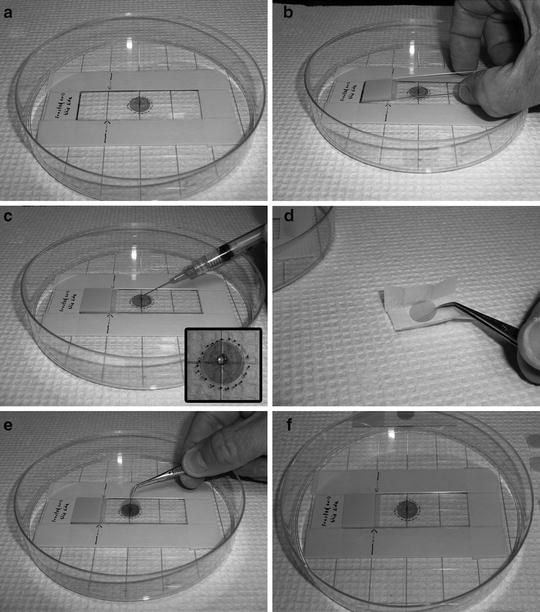
Fig. 5.
Image composite depicts a guided preparation technique to insure “on-center” substrates. (a) Our homemade guide setup for aligning and securing mica disks to glass slides; (1) depicts raised framework of layered masking tape to act as a guide to hold in place a (2) glass slide. (b) a blank glass slide within the tape framework; (c) a small drop of adhesive added on-center of glass slide; (d) an unwrapped mica disk being picked up with micro tweezers; (e) disk dropped on the top (center) of the adhesive drop; and (f) gravitational forces and the weight of the disk relative to the adhesive’s viscosity allow for an even distribution of the mounting medium, resulting in a level fastened substrate.
3.
Unwrap 0.5 in. mica disk(s) ready for mounting.
4.
Using a 23 G needle attached to a 3.0 mL syringe containing some mounting medium, place a small bead of the medium “on-center” on the precleaned glass slide.
5.
Immediately pick-up the 0.5 in. mica disk with the fine-point jeweler’s forceps and place “on-center” on top of the bead; gravity will do the rest.
6.
After several seconds remove the mounted mica substrate on glass support from the mounting guide and place on the bench-top surface for 24 h of drying.
7.
Repeat steps 2–6 to make as many of the mica substrates as desired; we typically make 50–100 and store in standard microscope slide boxes.
8.
Remember that the mica support should not be cleaved until immediately prior to use (see Subheading 3.3).
3.3 Adsorption of PSPC to Mica (See Note 3)
1.
Retrieve lipid vesicles from −20°C freezer.
2.
Upon thawing, check for any cloudiness of PSPC vesicles stock.
3.
Cloudiness warrants subsequent sonication of the solution for approximately 5 min (see Note 13).
4.
Using a P200 and a P1000 pipette dispenser, dilute and mix 100 μL of lipid vesicle stock with 400 μL of adsorption bilayer buffer in a 1.5 mL Eppendorf tube.
5.
Sonicate diluted vesicles for 5 min.
6.
Cleave mica prep on glass slide with Scotch 3M Translucent Tape.
7.
Carefully circumscribe an intact Pap Pen ring barrier around the mica disk, several millimeters from the edge.
8.
Pipette the diluted PSPC membrane vesicles onto the freshly cleaved mica support to a volume of approximately 150 μL; this is the maximum volume that maintains an intact and complete meniscus (Fig. 6; see Note 14).
Fig. 6.
Illustration of moisture chamber for incubating lipid membranes.
9.
Incubate and adsorb vesicles (fusion method) for approximately 1.5–2.0 h at room temperature in a covered moistened glass petri culture dish(s) (moisten chamber(s) with Whatman filter paper) (Fig. 6; see Note 15).
10.
Add 50 μL of same buffer before beginning to rinse; rinse away the non-adsorbed vesicles by adding– removing 50 μL of fluid volume from the meniscus with fresh buffer and with continual re-adding–removing the same amount of corresponding imaging buffer. Repeat this washing procedure approximately 30 times or for a total volume of approximately 1.5 mL of fresh buffer solution (see Note 16).
11.
Remove the previously (prior to rinsing) added 50 μL of buffer from meniscus and incubate substrate preparation(s) for a further 1.5–2.0 h at room temperature before placing chambers in 4°C refrigerator.
12.
Incubate fused preparations overnight, or longer at 4°C; preparations are viable for up to a week as long as sufficient buffer covers the sample.
3.4 Addition of Protein(s) (See Note 17)
1.
Using a P20 pipette dispenser, add 5.0 μL of protein (i.e., β2GPI cofactor at 0.33 mg/mL) to the 150 μL buffer meniscus covering the formed artificial lipid membrane, and incubate at 4°C overnight or longer; this results in the formation of patches of cofactor (antigen to which mAb aPL binds) of varying sizes (10).
2.
Prior to image session(s) remove desired number of preparations from the refrigerator and place on level and vibration-free laboratory countertop.
3.
Allow sufficient amount of warm-up time to room temperature.
4.
5.
Transport preparation(s) with meniscus volume near 150 μL.
3.5 Operation of the Asylum Research MFP-3D BIO AFM (See Note 18)
1.
Turn the laser “On” by turning the “Laser Key” to the right (clockwise). When not in use leaving the laser “Off” prolongs its lifetime.
2.
Turn “On” the fiber optic light source via “toggle button”; “red” portion of switch should be showing.
3.
Determine which probe type and cantilever holder (standard or i-Drive) will be required for the imaging session (see Note 19).
4.
Locate and choose the tools (small “Philips” screwdriver or small “straight” screwdriver, fine tweezers, etc.) necessary to mount and secure imaging probe to the chosen cantilever holder.
5.
Mount and secure the probe of choice in the cantilever holder.
(a)
Set out cantilever changing stand (Fig. 7a).
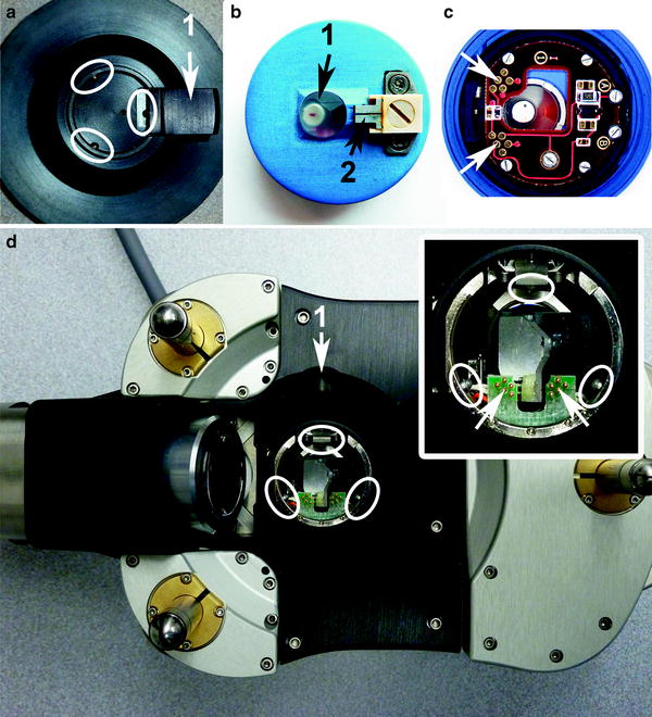
Fig. 7.
This image shows a few integral components of the atomic force microscopy (AFM) that require careful handling and positioning when mounting cantilevers on cantilever holder and holder on the changing stand and head. (a) A portion of the cantilever holding stand with the kinematic bearings (white ellipses) and the 1 lever; (b) top of the i-Drive holder with 1 crystal optical window and underlying shielded and sealed NbFeB magnet and 2 retaining clip which secures the silicon chip; (c) bottom side of the i-Drive holder with “pogo” contacts (white arrows); (d) with inset shows bottom side of head and analogous kinematic bearings (white ellipses) which accommodate kinematic mounting points of the holder and protruding “pogo” pins (white arrows) which align with the “pogo” contact spots; 1 indicates location of head’s lever which is sealed under a black rubber dome. The three legs are visible in this underside view of the head.
(b)
Choose cantilever holder; standard or i-Drive (see Note 20).
(c)
Place cantilever holder on the changing stand; locate and make note of location of kinematic mounting points and “pogo” contact locations underneath (Fig. 7a, c).
(d)
Orient the cantilever holder with “retainer clip” screwheads towards and near the lever on the stand.
(e)
Press the stand lever down and at the same time angle the cantilever holder into the stand; opposite the lever are two fixed silver bearings in the stand that must match up with the two symmetric, kinematic mounting points (oval grooves) on the cantilever holder.
(f)
Lower the cantilever holder, aligning and securing the third kinematic point with the silver bearing on the stand’s lever.
(g)
Release lever to lock cantilever holder in place on the cantilever changing stand.
(h)
Place cantilever changing stand on the stage of a low power binocular dissection microscope with a side light source and a top light source that is transmitted via top part of the microscope.
(i)
Inspect the holder for cleanliness; if not clean, follow cleaning instructions (see Subheading 3.5, step 21e).
(j)
Using a moisture-free air supply (Fisherbrand Air-It), gently blow areas (under cantilever clip, sides of quartz window, etc.) of cantilever holder; debris and bits of silicon can lead to improper seating of cantilever and suboptimal “AC mode” imaging.
(k)
Choose appropriate screwdriver (“Philips” for standard cantilever holder or “straight” for i-drive cantilever holder).
(l)
Have a box of cantilevers with appropriate tips handy (see Note 20).
(m)
Pick up a cantilever from the box with fine tweezers; while observing through the oculars of the binocular dissecting scope, slide the cantilever chip under the metal “restraint” clip.
(n)
Position the cantilever tip in the clear trapezoidal shaped quartz optical window.
(o)
Do not push the cantilever chip too far back under the restrainer clip, or else misalignment of the tip may ensue. The base of the chip and cantilever need to be parallel to the optical window surface.
(p)
Carefully, remove cantilever holder stand from dissecting microscope stage and place on the counter to gently finger tighten “Philips” or “straight” center screw.
(q)
Place the stand back on the microscope stage and recheck stability placement of cantilever chip; the chip should not move if nudged with tweezers, and must be firmly mounted to perform optimal “AC mode” and/or “Contact” imaging.
(r)
When using a shorter cantilever positioned next to a longer one on the chip, the longer cantilever should be removed (see Note 21).
6.
Install the cantilever holder onto the MFP-3D BIO AFM head (Figs. 7 and 8):
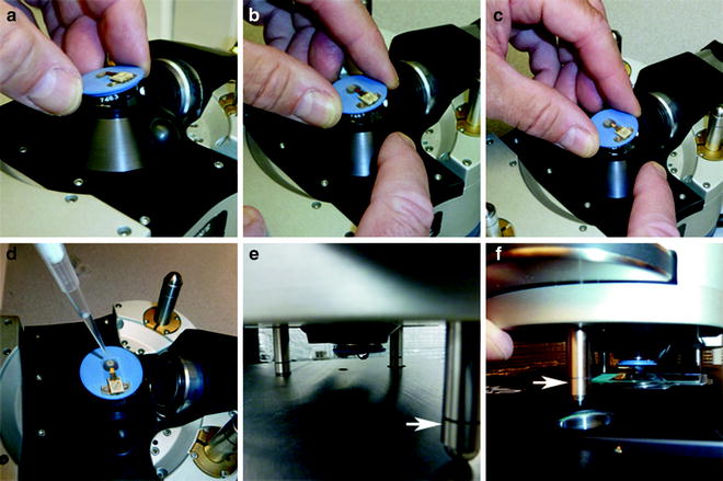
Fig. 8.
(a–f) A pictorial readiness from mounting holder on the head to placing head with cantilever over and into meniscus covering sample. While head is resting on the stainless steel platform with bottom side up, (a–c) position and secure the i-Drive cantilever holder onto the MFP-3D BIO AFM head. Once head is connected perform the following steps: (d) submerge the probe with solution; (e) flip head right-side up, check solution drop, move to x,y scanner stage, and place back legs in respective holes; and (f) lower probe into meniscus, gently lowering the front leg (white arrow) of the head with thumbwheel.
(a)
(b)
Next, remove the cantilever holder from the cantilever changing stand (Fig. 7a) by pressing the stand lever down with an index finger and holding the cantilever holder with the opposite hand.
(c)
Transport the cantilever holder to the acoustical enclosure and place carefully in the AFM “head assembly” by tilting it in at the “pogo” pins (Fig. 8a).
(d)
While tilting, align the kinematic points (grooves) with the two corresponding silver bearings; slightly slide into place while lowering the third kinematic point in register with the third bearing opposite the black release button (Fig. 8b).
(e)
Press and release the black button on the right to lock it in place; the end at the “pogo” pins will lift slightly upon seating (Fig. 8c).
7.
Start the MFP-3D BIO software as follows:
(a)
Click on the desktop icon titled AR that resides to the far left of the right monitor screen (see Note 22).
(b)
Igor Pro software compatible with the AR MFP-3D BIO AFM software chosen will appear; a strange chime will sound at this point (see Note 23).
(c)
Next, go to file > Load AFM Software (located at the bottom of pop-up window).
(d)
Click on Load AFM Software; the standard (basic) MFP-3D BIO “mode template” appears with accompanying “Holder” (Cantilever or Sample) panel and “Mode Master” panel. The “SmartStart Bus Recognition” feature will identify which type of cantilever holder is connected to the “Head”; panel usually pops up if no holder is recognized.
(e)
Choose desired imaging mode (or a personalized profile/preference) from the “mode master”; if returning to continue with a saved experiment (*.pxp), then click on file > open experiment and continue from there.
8.
Toggle the video camera window (and “Video Panel”) on:
(a)
Click on the camera (MFP3DXop v28up109) icon at bottom of screen.
(b)
Go to input at the top of video window > click on “S-Video.”
(c)
Go to and click on “AFM Controls” > go to “Other” > click on “Video Panel.”
9.
At this step, the following needs have to be verified before continuing.
(a)
Is the word “Ready” present in the lower left corner of the left monitor?
(b)
Is the “green” checkmark for “ARC Ready” present?
(c)
Is the “green” checkmark for “MFP-3D Ready” present?
(d)
Is the video camera window for viewing the cantilever displayed?
(e)
Are the following panels displayed?
(i)
Master Panel.
(ii)
Master Channel Panel.
(iii)
Sum and Deflection Meter Panel.
(f)
Affirmative responses to these questions indicate that the system is ready to continue.
10.
Get Clinical Tree app for offline access
Return to the BCH-45 acoustic hood enclosure to do the following:
(b)
Secure the specimen substrate support (i.e., glass specimen slide with a freshly cleaved mica disk) with two black magnets; one at each end of the glass slide (Fig. 4).
(c)
Place 200 μL of buffer on the freshly cleaved blank mica surface.
(d)
Place a bead of buffer on the cantilever holder’s triangular optical window until the cantilever (mounted probe) is submerged (Fig. 8d).
(e)
 Histochemical Detection of Lipid Droplets in Cultured Cells
Environmental Scanning Electron Microscopy Gold Immunolabeling in Cell Biology
Histochemical Detection of Lipid Droplets in Cultured Cells
Environmental Scanning Electron Microscopy Gold Immunolabeling in Cell Biology
 Colocalization Analysis in Fluorescence Microscopy
 Atomic Force Microscopy Functional Imaging on Vascular Endothelial Cells
 Imaging Non-fluorescent Nanoparticles in Living Cells with Wavelength-Dependent Differential Interference Contrast Microscopy and Planar Illumination Microscopy
 Environmental Scanning Electron Microscopy in Cell Biology


Next, grab the MFP-3D BIO AFM “head assembly” from the “mounting platform” with both hands.
Related posts:
Histochemical Detection of Lipid Droplets in Cultured Cells
Environmental Scanning Electron Microscopy Gold Immunolabeling in Cell Biology
Colocalization Analysis in Fluorescence Microscopy
Atomic Force Microscopy Functional Imaging on Vascular Endothelial Cells
Imaging Non-fluorescent Nanoparticles in Living Cells with Wavelength-Dependent Differential Interference Contrast Microscopy and Planar Illumination Microscopy
Environmental Scanning Electron Microscopy in Cell Biology
Stay updated, free articles. Join our Telegram channel
Full access? Get Clinical Tree
