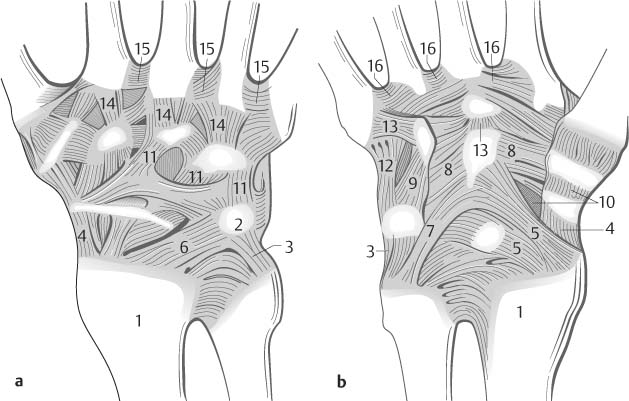
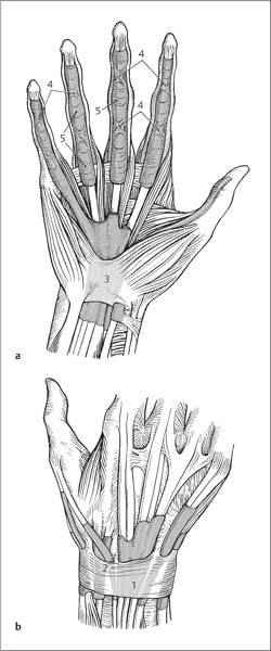
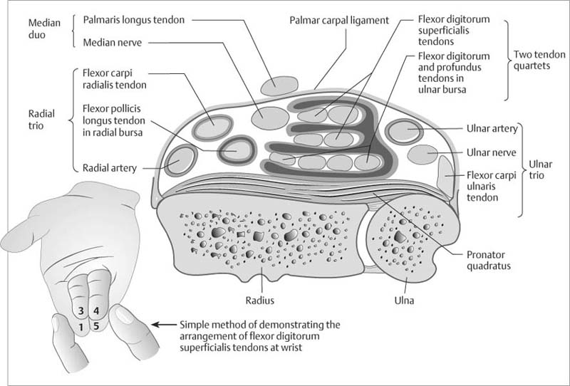
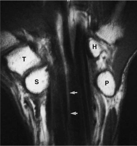
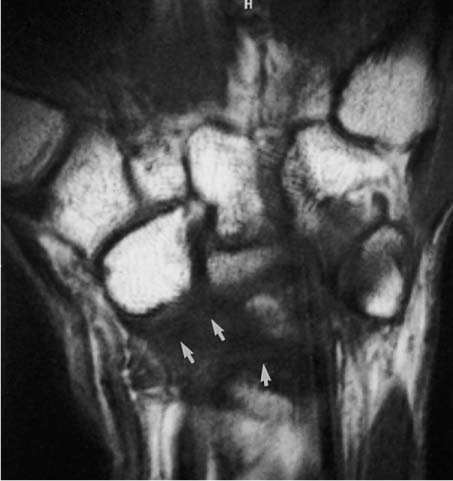
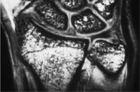
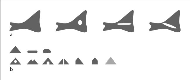
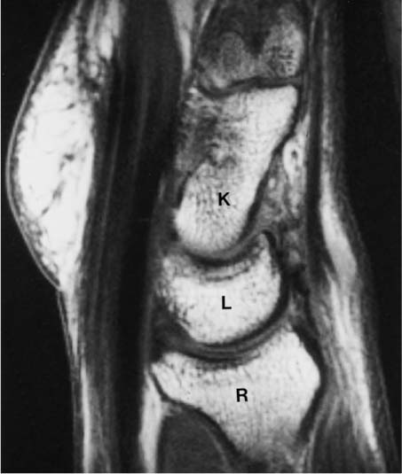
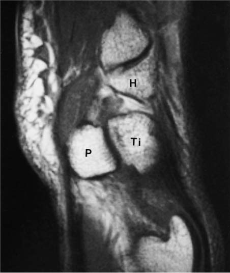
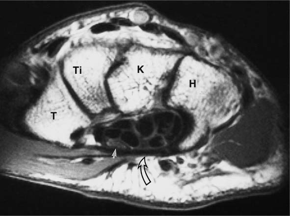
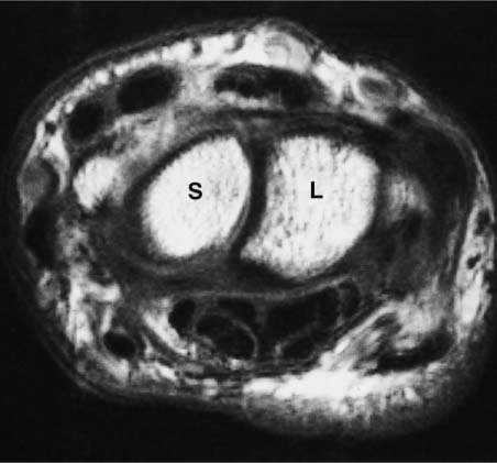
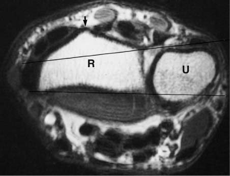
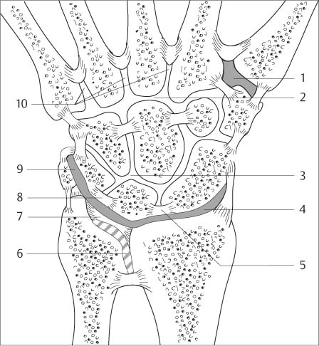
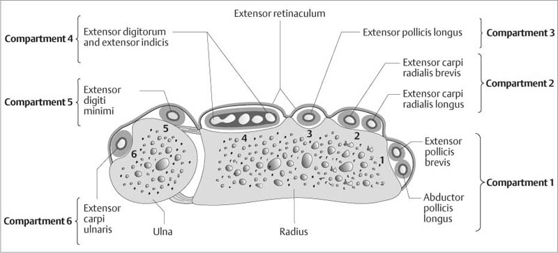
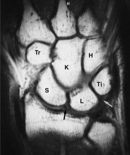
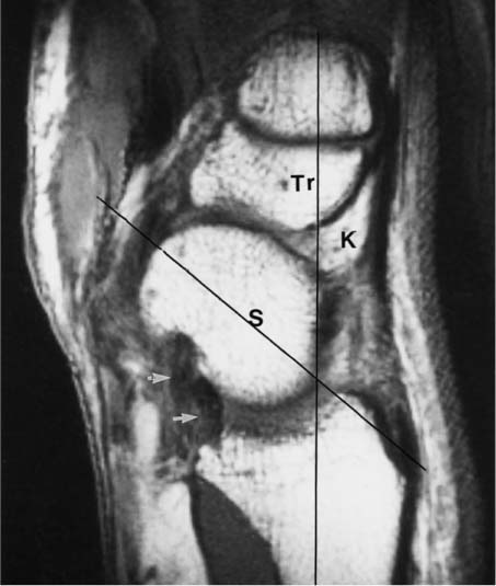
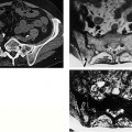
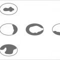
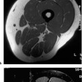
5 Wrist MRI is used less frequently for the wrist than for knee or shoulder since the wrist has fewer conditions with established MRI indications, such as ligamentous injuries, soft tissue and bone tumors, or inflammations. Furthermore, positioning in the MRI gantry is difficult and burdensome for the patient unless special coils are used. With the right auxiliary equipment, however, the 〉small’ wrist is suitable for imaging at a high resolution by using appropriate surface coils. The wrist is the most complex joint of the human body and poses high technical demands on diagnostic imaging, and it is here that MRI has opened new diagnostic avenues and will continue to forge the diagnostic and therapeutic approach in the future. The position should be as comfortable as possible for the patient. The best results can be achieved by using small Helmholtz-type surface coils or flexible coils that keep the wrist next to the patient’s body while the patient is placed in a comfortable supine position. An off-center field of view is a prerequisite for this examination technique. For examinations performed in the center of the magnetic field, the patient has to be prone with the arm extended above the head. This position might be difficult for older patients and those with shoulder complaints. Excellent images can be obtained by using a temporomandibular joint coil incorporated in a head coil, but the patient must be in the lateral decubitus or prone position with the arm extended above the head. This position again is uncomfortable and often the patient can hold still without moving the arm for a few image acquisitions only. Examinations of the head require the highest spatial resolution and should be performed only with dedicated surface coils. Circular coils with a diameter of 8 – 15 cm are most frequently used. The wrist is placed on or into the coil. Usually a field of view of 6 – 8 cm is large enough, which can be achieved with a coil diameter of 5 – 6 cm. Such small surface coils must have strong gradient fields to achieve this field of view for the applied sequence parameters. Conventional coils have the disadvantage of a rapid signal loss with increasing distance from the center of the receiver coil. A homogeneous distribution can be achieved with Helmholtz-type coils or flexible coils. Each examination of the wrist should include a coronal section. It provides a survey image of the bone marrow of all carpal bones and, at the same time, visualizes the distal forearm and the metacarpal bones. The sagittal plane is most suitable for visualizing the axial relationships of instabilities and for revealing any posterior or anterior subluxations. The transverse plane is primarily used for the evaluation of the carpal canal. Furthermore, it is the plane mandatory for delineating the extent of tumors and their pattern of infiltration. For the wrist proper, it can also assist evaluating the palmar or dorsal capsule and the synovial tendon sheaths. Coronal T1-weighted and T2-weighted images as well as sagittal T1-weighted images have been proven useful for finding the causes of unclear carpal pain. STIR sequences have been quite helpful for the sensitive detection of effusions and bone marrow edema. Contrast Enhancement. This frequently provides additional information. IV contrast medium is indicated whenever the findings are unclear. 3D-GRE Sequences. These allow sections less than 1 mm in width, which are especially advantageous for evaluating the triangular cartilage complex, but are rarely obtained in routine imaging. Since GRE sequences are sensitive to different magnetic susceptibilities, they can display an increased sclerosis in osseous regions. Rapid GRE Sequences Applying these sequences repetitively at short intervals (three sections within 10 sec.) can display enhancement dynamics in inflammatory and tumorous tissue. This technique can be used to monitor inflammatory conditions (rheumatoid arthritis) during therapy and, furthermore, might clarify the type of tumors (hemangioma) and reveal therapeutic responses (radiation therapy, chemotherapy). MR Arthrography. The use of MR arthrography for the visualization and evaluation of the triangular fibro-cartilage complex (TFCC) and interosseous ligaments is currently being assessed. Its fundamental disadvantage is the inability to visualize the flow of contrast medium from the mediocarpal joint into the radiocarpal joint and from the radiocarpal joint into the radioulnar joint as evidence of corresponding defects of the ligaments and triangular cartilage. Instilling contrast medium into several joint compartments is time consuming and currently its use is difficult to justify. However with more experience, use of the technique may increase. Cinematic Examination of the Wrist. This can be achieved with rapid GRE sequences and in the future also with echo-planar sequences. An interesting approach is the realtime visualization of motion by recording the images during movement of the patient’s hand. Whether this provides more information than conventional fluoroscopy remains to be seen and awaits the results of upcoming studies. The eight carpal bones can be divided functionally into a proximal row (scaphoid, lunate, triquetral, pisiform) and into a distal row (trapezium, trapezoid, capitate, hamate). The pisiform articulates with the triquetrum and can be considered to be a sesamoid in the flexor carpi ulnaris tendon. Functionally, it conforms neither to the proximal nor distal row. The articulation between distal radial articulating surface, distal ulna, triangular articular disk and proximal carpal row forms the radiocarpal articulation. In about 15% of the cases, it communicates with the pisotriquetral articulation. The proximal and distal carpal rows form the midcarpal joint. The distal carpal row and metacarpal bases constitute the carpometacarpal articulation, which has no motion because of strong connecting ligaments (amphiarthrosis). The articulation between the metacarpal bases is also referred to as intermetacarpal articulation. Separate articulations are the first carpometacarpal articulation (the sellar joint of the thumb) and the distal radioulnar articulation. The articulating surface of the radius is concave and forms a sigmoid notch for the ulna. The anatomic arrangement of the carpal ligaments is very complex. Interosseous (intercarpal) ligaments, which partially compartmentalize the internal joint capsule and as such are intrinsic, are distinguished from extracarpal ligaments, which reinforce the joint capsule and are extrinsic. Intrinsic ligaments: The proximal carpal row is interconnected by the interosseous ligaments between scaphoid and lunate (SL ligament) and between lunate and triquetrum (LT ligament), (Fig. 5.1) and forms a functional unit. These ligaments prevent a communication between the radiocarpal and mediocarpal articulations. Like all fibrous and ligamentous structures of the body, they are subject to degeneration, and defects in the SL ligament and LT ligament are found in about 30% of asymptomatic older patients. The distal carpal row is also interconnected by interosseous ligaments (Fig. 5.1). The configuration of the interosseous ligaments and the ulnar disk creates different joint compartments (Fig. 5.1). Familiarity with these compartments is a prerequisite for the performance and interpretation of arthrography. In MRI, the distribution of fluid accumulation or effusion within the individual compartments can be used to localize the site of a pathologic process. Extrinsic ligaments: The entire carpal region is enveloped by a firm fibrous capsule, partially reinforced by strong ligaments (Fig. 5.2). On the palmar side, the radiocapitate ligament, which is a part of the palmar radiocarpal ligament, extends from the radial styloid process across the waste of the scaphoid to the capitate. The radiotriquetral ligament, also part of the palmar radiocarpal ligament, arises from the ulnar aspect of the radial styloid process and follows a similar diagonal direction. It crosses the lunate and connects with fibrous extensions to it (part of the palmar radiocarpal ligament). On the ulnar aspect of the palmar carpal region, fibrous bands arise from the ulnar styloid process and fuse with the triangular fibrocartilage complex. Since these ligaments form a ‘V’ with the radial palmar ligaments, these structures are also referred to as proximal or distal V-ligaments. There are two strong diagonal ligaments on the dorsal side. The proximal ligament extends from the radial styloid process over the lunate to the triquetrum, called the dorsal radiotriquetral ligament, and represents the dorsal component of the carpal sling. The triquetrum can be imagined as the stone placed in the sling. From the triquetrum, broadly fan-shaped fibers extend over the distal carpal row to the trapezium, constituting the dorsal carpal ligament. Radial and ulnar collateral ligaments are seen on the respective sides of the carpal region. The triangular articular disk is composed of fibrocartilage and is positioned between the distal ulna proximally and the triquetrum and lunate distally. It has a flat triangular configuration, extends into the hyaline cartilage of the distal articulating surface of the radius and fuses imperceptibly with a complex structure of fibers and ligaments between the ulnar styloid process and proximal carpal rows. Fig. 5.1 Schematic drawing of a coronal section through the wrist to illustrate the compartmentalization of the carpal region into five articular compartments by the interosseous ligaments and triangular disk (after Greenspan). 1 = Compartment of the first carpometacarpal articulation 2 = Common carpometacarpal compartment 3 = Mediocarpal compartment 4 = Radiocarpal articulation 5 = Scapholunate ligament 6 = Distal radioulnar articulation 7 = Triangular disk 8 = Ligament between lunate and triquetrum 9 = Ligament between pisiform and triquetrum 10 = Intermetacarpal compartment Fig. 5.2a, b a Posterior and b anterior view of the extrinsic ligaments (after Kahle and co-workers). 1 = Radius Ligaments between distal forearm and carpal bones: 3 = Ulnar collateral ligament 4 = Radial collateral ligament 5 = Palmar radiocarpal ligament 6 = Posterior radiocarpal ligament 7 = Palmar ulnocarpal ligament Ligaments between carpal bones: 8 = Radiate carpal ligament 9 = Pisohamate ligament 10 = Palmar intercarpal ligaments 11 = Posterior intercarpal ligaments Ligaments between carpal and metacarpal bones: 12 = Pisometacarpal ligament 13 = Palmar carpometacarpal ligaments 14 = Posterior carpometacarpal ligaments Ligaments between metacarpal bones: 15, 16 = Metacarpal ligaments Two bands of fibers of the ulnar attachment are distinguished: one at the ulnar styloid process and one at the base of the distal ulna. Its undersurface glides over the head of the distal ulna covered with hyaline cartilage. The ulnar component of the radiocarpal articulation is distal to the triangular disk. The central and radial portions of the disk are not vascularized and, in contrast to the ulnar portion of the disc, show poor spontaneous healing after trauma. Because of its vascularization, the ulnar aspect of the disk has a higher signal intensity. Since it is difficult to separate the multiple fibrous structures of the ulnar side of the carpal region by imaging, the triangular disk and its ligamentous complex are simply referred to as triangular fibrocartilage complex (TFCC). Apart from the disk, this complex includes the dorsal and palmar radioulnar ligaments, a variably manifested ligamentous structure between triquetrum and ulna (so-called ulnocarpal meniscus or meniscal homologue), the ulnar collateral ligament, two ulnocarpal ligaments, the ulnolunate ligament and the ulnotriquetral ligament. The ulnocarpal meniscus can occasionally contain an accessory ossicle, called the os triquetrum secundarium or os triangulare. The opening to the prestyloid recess, also referred to as the ulnar recess and representing an extension of the joint capsule, is between discus and meniscus. Fig. 5.3a, b Anatomy of the tendons and tendon sheaths of the hand. a Anterior (palmar) view of the flexor tendons. b Posterior (dorsal) view of the extensor tendons (after Kahle and coworkers). 1 = Extensor retinaculum 2 = Septa of the retinaculum 3 = Flexor retinaculum 4 = Cruciate ligaments 5 = Annular ligaments Like the midcarpal articulation, the radiocarpal articulation contributes to flexion and extension as much as to radial and ulnar abduction. Flexion occurs to a greater degree in the radiocarpal articulation and extension is somewhat greater in the midcarpal articulation. The scaphoid undergoes the most conspicuous changes between radial and ulnar abduction of the wrist. Its normally 45 to 50 degree palmar inclination relative to the longitudinal axis of the radius rotates palmarly with radial abduction, while it extends upright and fills the space between distal radius, trapezium and trapezoideum with ulnar abduction. After passing through the openings and channels of the wrist, the muscle tendons are surrounded by synovial sheaths, which are arranged in several tendon sheath compartments (Fig. 5.3–5.5). Fig. 5.4 Anatomy of the tendons and tendon sheaths of the hand. Cross section at proximal wrist to illustrate the six extensor compartments (after Netter). Fig. 5.5 Anatomy of the tendons and tendon sheaths of the hand. Cross section proximal to the flexor retinaculum to illustrate the flexor tendons (after Netter). Fig. 5.6 Normal anatomy. Coronal T1-weighted SE image. The bone marrow spaces of the carpal bones exhibit a homogeneous signal. The interosseous ligaments (scapholunate ligament = SL, lunotriquetral ligament = LT) are identified as low signal structures (arrows). S = Scaphoid L = Lunate Ti = Triquetrum Tr = Trapezoid C = Capitate H = Hamate Fig. 5.7 Normal anatomy. Coronal T1-weighted SE image. The carpal canal with its low signal flexor tendon is visualized. The linear high signal structure seen centrally is a section of the median nerve (arrow). The Guyon canal is between the hamulus of the hamate and pisiform. S = Distal pole of the scaphoid T = Trapezium P = Pisiform H = Hamulus of the hamate Coronal Plane. This is the standard plane for visualizing the wrist. The bone marrow space of the carpal bones, especially lunate and scaphoid, can be easily evaluated, showing a homogeneous signal of high intensity on T1- weighted sequences (Figs. 5.6–5.8). Punctate decreases in signal intensity can correspond to bone islands, small cysts or nutrient vessels. The homogeneously high signal intensity reflects the absence of hematopoietic bone marrow in the distal extremities. The interosseous scapholunate and lunotriquetral ligaments are not definitively visualized in the coronal plane. Since the lunotriquetral ligament is slightly smaller, it can be evaluated less often than the scapholunate ligament. These ligamentous structures do not occupy the entire inter-carpal spaces and are more arranged along the peripheral contact zone. Consequently, the coronal plane visualizes these ligaments at the radiocarpal articulation and not at the mediocarpal articulation (Fig. 5.9). As found at the remaining intercarpal articulations, the interspaces are filled with hyaline cartilage of the respective carpal bones. The somewhat stronger scapholunate ligament shows variations where it is attached at the hyaline cartilage of the scaphoid and lunate. A broad zone of attachment along the proximal articular surface of the lunate is the most frequently encountered finding. Like the capsular ligaments and fibrocartilaginous disk complex, the interosseous ligaments exhibit a low signal intensity in all sequences. Fig. 5.8 Normal anatomy. Coronal T1-weighted SE image. The radial aspect of the proximal and distal V ligament (radiocapitate ligament, radiotriquetral ligament) is visualized. These fibrocartilaginous structures can deviate by exhibiting an artificial increase in signal intensity on T1- and T2*-weighted and protein density weighted images in certain joint positions, unrelated to and not to be mistaken for a pathologic process (see magic angle phenomenon, Appendix, p. 378). Furthermore, an increasing number of published articles have reported various patterns of increased signal intensities, particularly in thin sections, in the scapholunate and lunotriangular ligaments of asymptomatic pattern, attributed to degenerative changes (Fig. 5.10). These increases in signal intensity can be punctate or linear and can occur both along the course of the ligament or at the osseous attachment. Moreover, thin MRI sections can reveal morphologic variants that can be triangular, linear or amorphous. The ulnar disk has degenerative changes beginning in the third decade, causing increased signal intensities not to be mistaken for acute ruptures or inflammations. Histologically, these areas show a decreased number of chondrocytes as well as an altered fibrous matrix. The T1– and T2-weighted images show focal and linear increases in signal intensity (Fig. 5.10). Linear signal intensities that extend to the surface generally correspond to a complete chronic rupture. These degenerative changes progress with age but are rarely symptomatic. Fluid or effusion is not detectable in the capsule or recesses of the carpal joints of most healthy wrists, though it can be normal to observe a small amount of fluid on T2-weighted, STIR and GRE sequences. An effusion exceeding 1 – 1.5 mm in width should be considered pathologic. The coronal plane also allows the evaluation of the triangular fibrocartilage disk. However, the disk is seen with 3 mm sections only on one or two sections. Thin sections of 1.5 – 2 mm are recommended for the region of the triangular fibrocartilage disk. The low-signal fibers of the triangular fibrocartilage disk radiate into the distal radial articular surface and exhibit a broad-based attachment along the radiocarpal articulation and more proximal along the radioulnar articulation. Fig. 5.9 Coronal 3D GRE image of a healthy subject. The scapholunate and lunotriquetral ligaments exhibit a triangular configuration and contain a somewhat heterogeneous signal increase centrally. High signal cartilage is seen at the base. The ulnar portion of the extrinsic ligaments is well delineated and consists of the triangular fibrocartilage complex with high signal radial attachment formed by the cartilaginous cover of the radius. The high signal on the ulnar site is caused by vascularized connective tissue. The so-called meniscus homologue (meniscus ulnocarpalis) is further distal with the ulnar collateral ligament along its ulnar side. Sagittal Plane. Images in the sagittal plane show the axial relationship of the carpal bones to each other. In particular, the axes of the radius, lunate, capitate and scaphoid can be measured as on a lateral radiographic view but without interfering superimpositions (Figs. 5.11–5.13). Palmar or dorsal subluxations are accurately visualized on the lateral plane only. Even minor subluxations as well as early localized cartilaginous degenerations can be detected. The sagittal plane is therefore mandatory for the evaluation of instabilities and degenerative changes. Furthermore, it discloses the structural changes of the lunate in patients with avascular necrosis of the lunate. Fig. 5.10 a, b Variable visualization of the triangular disk and the intrinsic ligaments between the lunate and scaphoid and between the lunate and triquetrum. a The fibrocartilaginous triangular disk is usually seen as structure of low signal intensity or signal void (left). Age-related degeneration induces increases in signal intensity, which initially are focal and later appear linear with possible extension to the surface (from left to right). b The intrinsic ligaments of the proximal carpal row are seen usually as low signal intensity to signal void and are triangular in shape (about 60%). Form variants can lead to a more linear (about 30%) or more amorphous (more than 10%) visualization. The signal changes consist of (from right to left) focal increase in intensity in the center, at the tip (about 5%) or base (about 3%), linear and still central increase (about 10%), and unilateral or bilateral increase at the attachment as well as a diffuse increase. Fig. 5.11 Normal anatomy. Sagittal T1-weighted SE images. Scaphoid and its articulation with the trapezium and trapezoid are seen in part. On the palmar aspect, the radioulnar and radiotriquetral ligaments are diagonally transected (arrows). The longitudinal axis of the wrist (the vertical line along the radio-lunate-capitate-metacarpal axis) and the 30 to 60 degree tilted scaphoid axis are superimposed. S = Scaphoid C = Capitate T = Trapezoid Fig. 5.12 Normal anatomy. Sagittal T1-weighted SE images. The normal alignment of radius, lunate and capitate is apparent. The flexor tendons are seen on the palmar aspect. L = Lunate C = Capitate R = Radius Fig. 5.13 Normal anatomy. Sagittal T1-weighted SE images. The pisotriquetral articulation and the ulnar styloid process are visualized. H = Hamate Ti = Triquetrum P = Pisiform Transverse Plane. The axial or transverse plane displays the carpal tunnel with its contents. The retinaculum, which extends between distal scaphoid, tubercle of the trapezium and hamulus of the hamate, is seen as structure of low signal intensity (Fig. 5.14). The median nerve is immediately beneath it and, because of its water and fat content, has a higher signal intensity than the flexor tendons in all sequences. Positional variants of the median nerve are well recognized on all transverse images and should not be mistaken for pathologic displacements. Moreover, the compartment for the ulnar nerve, the Guyon canal, can be adequately evaluated in this plane. The superficial and deep flexor tendons are also distinctly delineated (Fig. 5.15), and inflammatory changes or effusions of the tendon sheaths can be easily detected on T2-weighted images. Furthermore, the palmar and dorsal capsular ligaments are displayed on the transverse images, especially if pathologic changes are present. Only the transverse images can adequately display the anatomic position of the radioulnar joint and can detect even minor palmar or dorsal subluxations (Fig. 5.16). Fig. 5.14 Normal anatomy. Transverse T1-weighted SE images. The flexor retinaculum is seen as structure of low signal intensity (open arrow). The flexor digitorum superficialis and profundus tendons also are seen as nearly signal void. The median nerve is relatively far on the radial aspect, appears transverse-ovoid and has an increased signal intensity relative to the flexor tendons (arrow). T = Trapezium Ti = Trapezoid C = Capitate H = Hamate with hamulus Fig. 5.15 Normal anatomy. Transverse T1-weighted SE images at the level of the scapholunate joint space. The capsular ligaments are stronger on the palmar side than on the dorsal side. S = Scaphoid L = Lunate Fig. 5.16 Normal anatomy. Transverse T1-weighted-weighted SE images at the level of the distal radioulnar articulation. Lister’s tubercle is seen at the dorsal aspect of the radius (arrow). Lines are drawn between dorsal and palmar corners of the radius to determine any malposition of the ulna. The ulna should not project beyond these lines by more than half the shaft width. R = Radius U = Ulna MRI has been become established as a very sensitive method for the detection of avascular necroses due to the direct visualization of pathologic processes involving the internal osseous structures. Bone scintigraphy has an equally high sensitivity but a lower specificity. Conventional radiographs and CT are negative in the early stages of avascular necroses. The most common manifestations in the wrist are the spontaneous avascular necrosis of the lunate (Kienböck disease) and, somewhat less frequent, the spontaneous avascular necrosis of the scaphoid (Preiser disease). Only a few case reports describe spontaneous avascular necroses affecting other carpal bones: trapezoid (Agati disease), osteochondritis dissecans of the pisiform (Schmier disease) and triquetrum (Witt disease) as well as multiple avascular necroses involving capitate, trapezium, and hamate (Brainard disease). Lunate avascular necrosis represents the progressive necrotic collapse of the lunate. Men are affected three to four times more often than women. It is generally unilateral but can be bilateral, possibly affecting each wrist at a different stage. Etiology. Various causative mechanisms are being discussed. Frequently, the patient remembers a trauma in the recent or remote past. Mechanical overuse of the wrist seems to play a role in some patients. For workers using a jackhammer, lunate avascular necrosis is a recognized occupational hazard. Incongruence of the radiocarpal articulation is considered a predisposing factor, most often manifested as relatively short ulna, less often as relatively long ulna (so-called ulna plus variant and ulna minus variant according to Hultén [Hultén 1928]). Symptoms. The symptoms generally begin between the ages of 20 and 40 years, but can become manifest after the fifth decade. The complaints often begin insidiously. Radiating wrist pain can last for years, leading to progressing active and passive restriction of motion and declining strength of grip. A swelling is observed on the dorsum of the hand, associated with local tenderness. Characteristically, passive extension of the middle finger is painful. Therapy. Depending on the stage of the disease, conservative therapy (immobilization for stage Decloux I and II) or surgically reconstructed articular congruence by means of ulnar extension or radial shortening (so-called leveling surgeries for stage Decloux II) should be considered. To avoid secondary degenerative changes and carpal collapse, a lunate resection is usually combined with plastic replacement using interposed tendons, silicon (Swanson prosthesis), Vitallium or even acrylic. Alternatively, an intercarpal fusion or extended resection with additional partial resection of adjacent carpal bones (e.g., Steinhäuser techniques) should be considered. Furthermore, transposing the pisiform into the lunate lodge is a surgical option. In stage IV disease, fusion or denervating surgeries as salvage procedures can provide symptomatic relief (Fig. 5.17). MRI is indicated if symptoms persist or worsen post-surgically and clinical and conventional radiologic findings are inconclusive. Familiarity with the surgical procedure is mandatory for interpreting postsurgical findings. Diagnosis. Diagnosing avascular necrosis of the lunate can be difficult since its early stage is radiographically unremarkable. Bone scintigraphy is a sensitive method and already positive in the early stages. The first radiographic finding consists of a subtle increase in density in the lunate in comparison with the other carpal bones. Cysts can develop within the lunate. Later in the disease, the lunate becomes fragmented. The fragmentation generally begins in the proximal subchondral region that articulates with the distal radius. Already in this stage, a functional insufficiency of the scapholunate ligament can develop, leading to a moderate rotatory subluxation of the scaphoid (RSS). This instability can progress to degenerative changes of the styloid as the first manifestation of osteoarthritis of the carpal bones. This is followed by progressive collapse with loss of height and dorsovolar ribbon-like elongation of the lunate. The proximal migration of the capitate eventually leads to a carpal collapse followed by a generalized osteoarthritis of the radiocarpal and mediocarpal articulations. With the progression of the structural changes, grip strength and range of motion decline. The osseous changes can be visualized well by conventional and computed tomography. Different staging classifications of lunate avascular necrosis on the basis of conventional radiographic findings have been advocated and described in publications by Stähl (1947, five stages), Decloux (1957, four stages) and Lichtman (1988, four stages). The staging proposed by Decloux is as follows: • Stage I: Increased density of the lunate, • Stage II: Geographic and/or linear radiolucencies,
Introduction
Examination Technique
 Positioning
 Coil
Coil
 Sequences and Parameters
 Special Examination Techniques
Anatomy
 General Anatomy
 Specific MRI Anatomy
Spontaneous Avascular Necroses
 Avascular Necrosis of the Lunate (Kienböck disease)
Related posts:

Stay updated, free articles. Join our Telegram channel

Full access? Get Clinical Tree


