
Artifacts
Artifacts in musculoskeletal ultrasound refer to features in the ultrasound image that do not reliably represent the anatomic structure underneath the transducer. Knowledge of artifacts is critical for reliably interpreting images in musculoskeletal ultrasound. Some artifacts such as anisotropy can be minimized with appropriate scanning technique. Others must be simply recognized for appropriate image interpretation. Artifacts can even provide clinical clues for underlying pathology in some circumstances. A detailed discussion of all of the potential artifacts that can be encountered with ultrasound is beyond the scope of this text; however, the more common ones are mentioned.
ANISOTROPY
Anisotropy is the most significant and commonly encountered artifact with the superficial structures in musculoskeletal ultrasound and it is particularly potentially problematic when using linear transducers. It refers to the property of tissue to differentially conduct or reflect sound waves back to the transducer based on the angle of incidence of the sound waves. Anisotropic artifact refers to a darkening and loss of resolution of the image (Figures 4.7 and 13.1). This occurs when the approach of the sound waves is less than perpendicular (ie, angle of incidence greater than 0 degrees) (Figure 2.7). Therefore, the examiner should attempt to keep the direction of the beam as close to perpendicular as possible.
Tendons are particularly prone to anisotropic artifact due to their high reflectivity and uniform linear orientation (Figure 9.10) (see Chapter 7). Most other tissues have a degree of anisotropy. Conspicuity of a needle is also affected by anisotropy. Effort should be made to maintain the incident sound wave as close to perpendicular to the needle as possible. This is discussed in more detail in Chapter 14. Techniques such as toggling the transducer and heel-to-toe rocking should be used to reduce anisotropy. These maneuvers are discussed in Chapter 5.
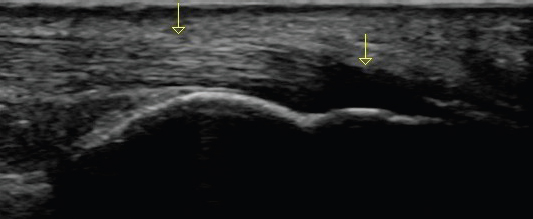
FIGURE 13.1 Sonogram demonstrating an example of signal change due to anisotropic artifact. The image displays a long-axis view of a normal Achilles tendon with insertion on the calcaneus. The yellow arrows represent the direction of the approaching sound waves from the transducer. The normal fibrillar architecture of the tendon is seen toward the left of the screen where the angle of incidence is orthogonal to the tendon. Note the hypoechoic appearance of the tendon fibers as they curve at a steep angle to insert into the calcaneus. This is anisotropic artifact related to this portion of the tendon not being perpendicular to the incident sound beam. This artifact can be resolved by performing a heel-to-toe rock with the transducer to change the angle of incidence to the distal portion. Failure to recognize the effect of anisotropy on an image like this could lead to an erroneous conclusion of pathology.
INADEQUATE CONDUCTION MEDIUM
Ultrasonography requires a sufficient amount of conduction median between the transducer and the skin of the patient for the sound waves to adequately travel from the transducer to the tissue and back to provide a clear image. This is usually done with conduction gel (Figure 13.2) or less frequently stand-off pads. This is necessary because ultrasound waves do not conduct well through air. They need a medium such as gels or liquid to create a good image. The examiner should use a liberal amount of conduction gel to avoid the artifact caused by a lack of effective sound wave transmission (Figure 13.3).
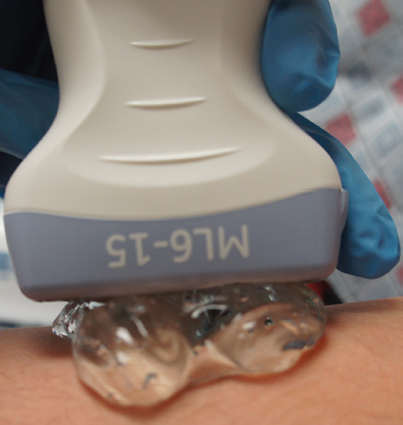
FIGURE 13.2 Picture demonstrating the use of conduction gel to enhance the transmission of sound waves between the tissue and the transducer.
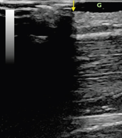
FIGURE 13.3 Sonogram demonstrating the effect of inadequate conduction gel on the ultrasound image. The tissue is relatively uniform superficial muscle. The right side of the image has gel under the transducer (the gel is the anechoic superficial region on the right side of the screen labeled G). Note that the tissue to the right of the yellow arrow is under the gel and clearly visible. The left darkened area is under the portion of the transducer without the gel. This impaired image results from the lack of sound wave transmission between the tissue and the transducer in the field where there is not an adequate conduction medium.
POSTERIOR ACOUSTIC SHADOWING
Posterior acoustic shadowing refers to a darkening of the ultrasound image beneath a structure with a large amount of reflectivity. Examples of this include decreased signal underneath tumors, calcifications, or foreign bodies (Figure 13.4). The tissue below an object of higher impedance receives less of the incident sound waves than surrounding tissue that is not below that object and appears darker. Surveying the entire ultrasound image rather than simply focusing a single structure can help to identify posterior acoustic shadowing by recognizing the darkening throughout the image in a vertical line. This artifact is sometimes more evident than the appearance of the actual structure causing the posterior acoustic shadowing and can be used to help to identify the location of a tumor or foreign body.
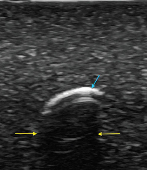
FIGURE 13.4 Sonogram demonstrating the effect of posterior acoustic shadowing (yellow arrows) beneath a highly reflective foreign body (blue arrow).
POSTERIOR ACOUSTIC ENHANCEMENT
Posterior acoustic enhancement, also known as increased through transmission, occurs as a result of a focal area of decreased impedance that lead to an increased transmission of sound waves to the tissue immediately below it. It is essentially the reciprocal of posterior acoustic shadowing. Cysts and veins are examples of structures that can lead to posterior acoustic enhancement (Figure 13.5). Because a greater amount of sound waves return to the transducer from tissue with less impendence above it, that tissue generally appears more hyperechoic. If the source of artifact can be compressed such as a vein, increased transducer pressure can reduce or eliminate it. Similar to other artifacts, the entire image should be analyzed to recognize the focal brightness seen throughout all of the tissue in a vertical line below the area of decreased impedance. In some circumstances, posterior acoustic enhancement can be used to provide clinical clues for assessment by enhancing conspicuity of underlying structures (Figure 13.6).
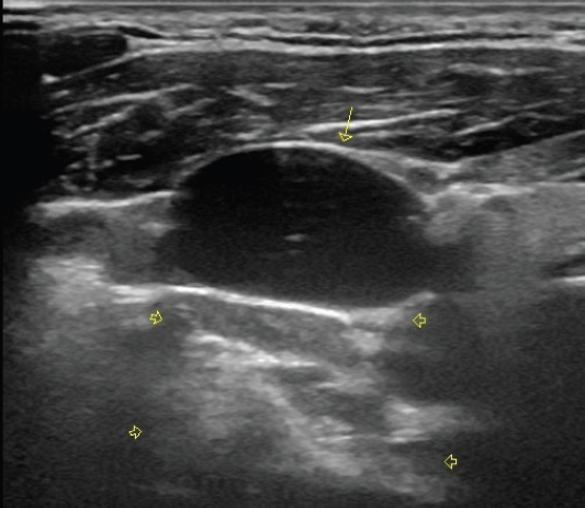
FIGURE 13.5 Sonogram of a short-axis view of the jugular vein (yellow arrow). Note that the tissue directly beneath the anechoic jugular vein (yellow arrowheads) is more hyperechoic than the tissue lateral to that. The effect is produced because the vein has less attenuation of the sound waves than the surrounding solid tissue.
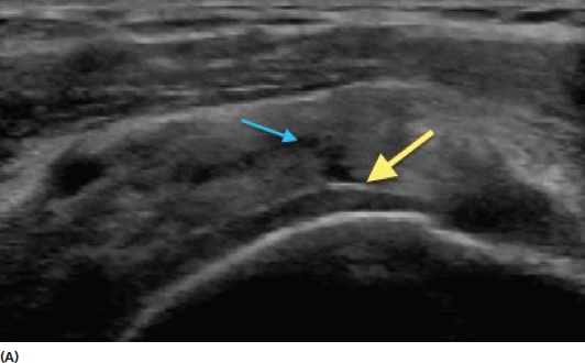
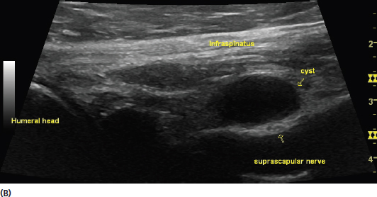
FIGURE 13.6 Sonograms demonstrating examples of posterior acoustic enhancement providing additional clinical clues. The image in (A) is a long-axis view of the supraspinatus tendon. In this image, the decrease in overlying tissue density as a result of the tendon tear (blue arrow) results in posterior acoustic enhancement and improved visualization of the border of the articular cartilage (yellow arrow). The enhancement of border of the cartilage is a clinical clue suggesting overlying rotator cuff tear, even in circumstances when the tear is less conspicuous. The image in (B) is a long-axis view of the infraspinatus tendon with a posterior labral cyst. This image shows good visualization of the suprascapular nerve that lies below the cyst. The nerve is often difficult to see with such clarity in ordinary circumstances.
REVERBERATION ARTIFACT
Reverberation artifact occurs as a result of repetitive reflection back and forth between two highly reflective surfaces (Figure 13.7). In musculoskeletal ultrasound, it is most frequently encountered with needle guidance and metallic implants (Figure 13.8). This artifact appears as equally spaced hyperechoic lines that blur the image. It is particularly important to recognize that this artifact makes the metallic structure appear thicker and deeper than it really is.
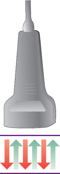
FIGURE 13.7 Illustration of the development of reverberation artifact. The sound waves bounce back and forth between a superficial object with high impendence and the transducer.
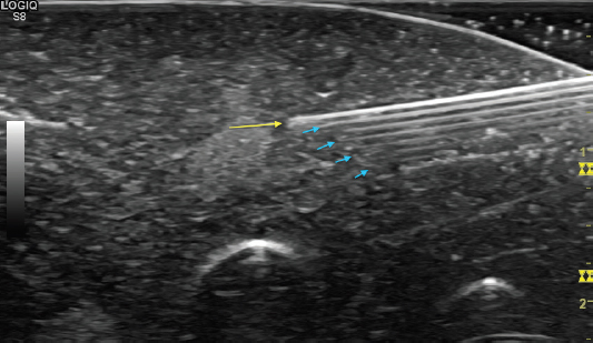
FIGURE 13.8 Sonogram demonstrating an in-plane view of a needle with reverberation artifact. The needle tip is identified by the position of the yellow arrow. The equally spaced hyperechoic artifact (blue arrows) is beneath the actual needle.
Other forms of specific descriptions of reverberation artifact include comet-tail and ring-down artifact. Comet tail artifact usually occurs because of reflection between two closely located structures. The tapering tail appearance results from attenuation of the artifact as it moves more deeply (Figure 13.9). Ring-down artifact looks similar, but is related to deep air pockets.
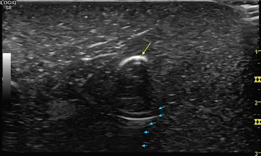
FIGURE 13.9 Sonogram demonstrating an appearance resembling comet tail artifact (blue arrows). The artifact lies beneath a highly reflective structure (yellow arrow) and tapers with attenuation as it extends deeper.
OTHER ARTIFACTS
There are many other types of artifacts seen with ultrasound and a detailed description is beyond the scope of this text. Many of them are related to variations in the signal between tissues of different densities. Ultrasound images are based on the assumption that sound waves are traveling through tissue at a relatively uniform speed (1,540 m/s in human tissue). Tissue variation with significantly different densities can potentially “fool” the instrumentation into creating an image that does not completely represent the anatomic structure. Excessive refraction and attenuation can also occur with tissues of differing densities. These types of artifacts more frequently are problematic in ultrasound of deeper structures as opposed to those typically viewed in a musculoskeletal evaluation.
REMEMBER 
1) The entire screen of the ultrasound image should be assessed to help detect artifact.
2) The transducer should be positioned so that the direction of the incident sound waves is perpendicular to the tissue of interest to minimize anisotropic artifact.
3) Posterior acoustic enhancement can sometimes be used to provide clinical clues and increased conspicuity of tissue.
Related posts:
Stay updated, free articles. Join our Telegram channel

Full access? Get Clinical Tree


