Ultrasound is the ideal imaging modality for guiding most peripheral joint, tendon, and nerve injections. It allows visualization of both the needle and soft tissue target in real time. This improves accuracy of needle placement for both injection and aspiration procedures and allows identification of neurovascular and other visceral structures for avoidance. The use of ultrasound guidance for various injections is often a matter of debate. Some argue that it is unnecessary for many simple injections, particularly those that have easily palpable landmarks. Others contend that accuracy is improved in even routine injections. There has yet to be a widespread consensus regarding which specific procedures are appropriate for ultrasound guidance. It is clear that it should be considered in circumstances where needle accuracy is needed for efficacy, safety, and/or visualization of the tissue effects of the procedure. Appropriate advanced planning will help ensure smooth execution of the procedure. A checklist of materials and equipment to be used should be reviewed in advance (Table 14.1). Sufficient time should be taken to inspect and establish that the correct medication and dosage is available. The needle gauge and length should be appropriate for the procedure planned. There must be adequate length to reach the target. This includes a needle for a local anesthetic when needed. TABLE 14.1 Equipment and Materials for Ultrasound Guided Procedures
Ultrasound Guidance for Injections
INDICATIONS FOR ULTRASOUND GUIDANCE
PLANNING THE PROCEDURE
| Medications (thoroughly examined for correct labeling and dosage) |
| Appropriate size and length needles |
| Local anesthetic (when needed) |
| Ultrasound machine with appropriate transducer (linear or curvilinear) |
| Skin preparation (sterilization) material |
| Gauge |
| Dressing or bandages |
| Sterilization material for the transducer or transducer cover |
| Gloves |
| Sterile drapes (when needed) |
Scanning the area of the procedure should be done in advance. This allows image optimization with the ultrasound machine as well as precisely determining the depth of the target for approach planning (Figure 14.1). A consideration for approach planning should be minimizing anisotropy of the needle. There is greater conspicuity when the incident ultrasound beam is more orthogonal to the needle (Figure 14.2). The needle is particularly more difficult to see when a steep angle is used for approaching deeper targets. For this reason, beginning the needle approach somewhat further from the target will facilitate a more perpendicular position and better needle visualization (Figure 14.3). When approaching a very superficial target, an oblique standoff of piled up sterile gel on one end of the transducer can allow visualization of the needle prior to contact with the skin (Figure 14.4).
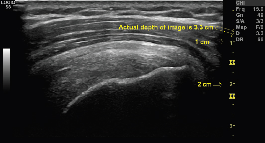
FIGURE 14.1 Sonogram demonstrating use of the measuring tool to determine the depth of the image. The sonogram is a long-axis view of the supraspinatus tendon. The depth of the entire image is shown. The markers to the right are also available to determine the depth at each level of the image in centimeters. Most ultrasound machines have measurement tools of this nature. They should be used in the prescan to determine the precise depth of the intended target in advance.
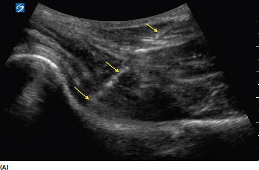
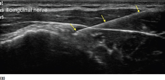
FIGURE 14.2 Sonograms demonstrating the effect of needle anisotropy with in-plane views of the needle. The image in (A) shows a long-axis view of the anterior hip. Note the more difficult needle visualization (yellow arrows) of a deeper injection. The image in (B) shows the improved conspicuity of a more superficial needle (yellow arrows). A needle that is more perpendicular to the incident sound beam is more easily visualized. Anisotropic artifact of deeper injections can be improved by initiating the injection further from the target to create a more perpendicular trajectory. The examiner can also use heel-to-toe rock of the transducer, or beam direction or steering, if available on the equipment, to increase the angle of incidence of the sound waves in relation to the needle.
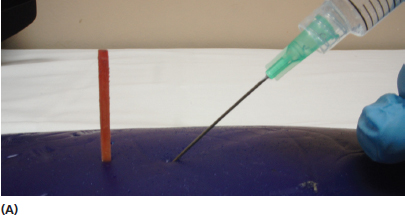
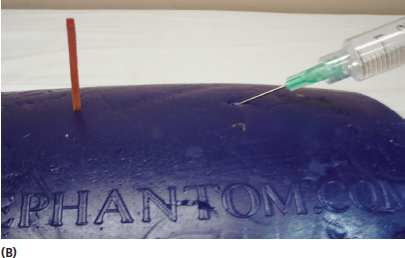
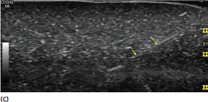
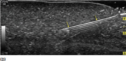
FIGURE 14.3 Pictures and sonograms demonstrating different needle approaches for the same target. The picture in (A) shows a steep trajectory toward the target. The picture in (B) shows an approach to the same target from a greater distance to apply a more orthogonal approach in relation to the transducer. The sonogram in (C) demonstrates the appearance of the needle (yellow arrow) from a steeper approach. The sonogram in (D) shows an in-plane view of the same needle (yellow arrows) with an approach that is more perpendicular to the needle. The disadvantage of this approach is that it results in the needle traversing through tissue over a greater length to reach the same target. The advantage is that it allows better visualization of the needle.
Scanning prior to the procedure provides help distinguishing undesirable areas for avoidance (Figure 14.5). During this time, the settings on the ultrasound machine should be reviewed including appropriate depth, focal zone placement, and frequency for optimization of the area to be visualized (see Chapter 4).
In addition to preparing the skin, antiseptic preparation of the transducer surface or a sterile transducer cover should be used to avoid contaminating the injection field. Use of alcohol-based chlorhexidine is preferred over povidone-iodine by some centers for skin preparation. Alcohol can potentially have adverse effect on the transducer crystals, so obtaining information from the manufacturer should be done prior to use of any substance with the transducer.
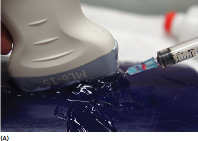
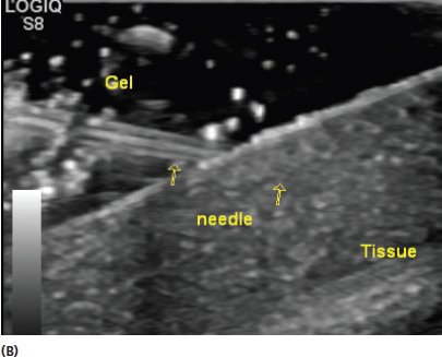
FIGURE 14.4 Demonstration of using a large amount of transducer gel to create an oblique standoff (A). This is reflected by the sonogram in (B). The oblique standoff of transducer gel allows visualization of the needle prior to making contact with the skin. This is particularly helpful when the target is a very superficial structure.
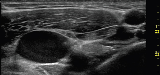
FIGURE 14.5 Sonogram demonstrating an example of an area where prescan planning and live guidance can help avoid undesirable placement of the needle. The image is an area of the neck with multiple neurovascular structures that could be avoided with proper technique.
Use of sterile probe covers can alleviate the need to sterilize the transducer surface (Figure 14.6). This is a good option because it allows free movement of the transducer in the field to optimize tissue and needle conspicuity.
The “no touch” method can also be used. This is accomplished by keeping the nonsterile transducer completely out of the sterile field (Figure 14.7). Although potentially time saving, this method presents the problem of the limitation of transducer movement in situations when the needle is difficult to visualize. It also provides a greater risk of sterile field contamination, particularly in less experienced practitioners.
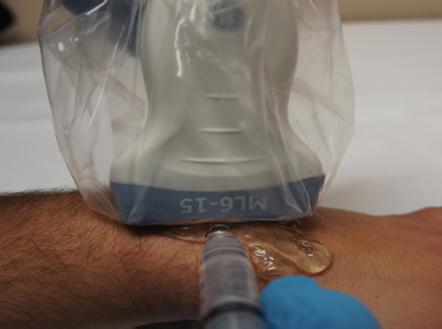
FIGURE 14.6 Picture of a transducer with a sterile cover. The cover allows movement of the transducer in the area of the procedure without contaminating the sterile field.
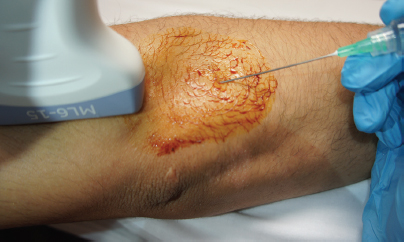
FIGURE 14.7 Picture demonstrating the “no touch” method of performing a sterile injection. The image is created at an angle to the target and the transducer is kept out of the sterile field.
The procedure should also be explained to the patient during the preparation period providing “informed consent.” It is also reasonable to explain the benefit and potentially improved accuracy of ultrasound guidance to the patient. Some patients may have had similar injections without guidance and be surprised by the additional preparation time. Anxiety can be alleviated with an explanation that the additional preparation provides a more accurate injection.
Consideration should also be given to the orientation of the transducer and needle relative to the anatomic target. The terms short axis and long axis refer to the position of the transducer relative to the anatomic target (Figure 14.8). The terms in-plane and out-of-plane refer to the orientation of the needle relative to the transducer. With in-plane orientation, the needle is parallel to the transducer. With out-of-plane orientation, the needle is perpendicular to the transducer (Figure 14.9). In-plane orientation is generally preferred for most injections for the advantage of visualization of the entire needle approach and needle tip (Figure 14.10). Out-of-plane injections can be used effectively in some circumstances, particularly when the target is superficial and close to the point of skin insertion. The needle in an out-of-plane view will appear as a hyperechoic dot (Figure 14.11). This view has the disadvantage of only showing a small cross section of the needle and not facilitating reliable visualization of the needle tip.
The arrangement of the patient and injection field in relationship to the ultrasound machine should also be considered in advance. Having the ultrasound screen in direct line with the needle and transducer will facilitate an easier injection by allowing visualization of all of these components without having to avert gaze away from the needle (Figure 5.8). Consideration of which hand will hold the transducer and which will be used to perform the injection should also be determined in advance. Many practitioners prefer to stabilize the transducer with the nondominant hand and perform the injection with the dominant hand. The time spent doing a plan of the injection approach with the preprocedure scan can provide considerable rewards for improving the ease of the injection.
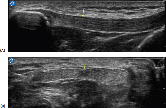
FIGURE 14.8 Sonograms demonstrating the appearance of the patellar tendon (yellow arrow) in long axis (A) and short axis (B).
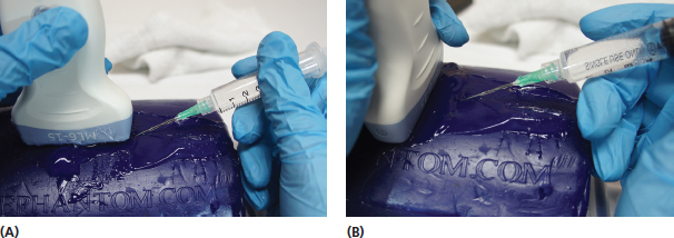
FIGURE 14.9 Pictures demonstrating the orientation of an in-plane (A) and out-of-plane (B) position of the needle relative to the transducer.
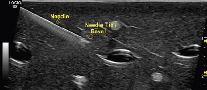
FIGURE 14.10 Sonogram demonstrating an in-plane view of a needle. This orientation is generally preferable for most injections as it allows visualization of the needle tip throughout its trajectory.
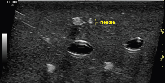
FIGURE 14.11 Sonogram demonstrating an out-of-plane view of the needle. This orientation is sometimes more challenging because the needle tip and length of the needle are not seen. In this view, the needle will appear as a hyperechoic dot when it moves into the field. It can be used successfully for needle introduction into small spaces over short distances.
PERFORMING THE INJECTION
Once the appropriate planning has been completed, the needle should be inserted with the same trajectory as determined during the prescanning period. Once the target has been identified on ultrasound, the needle must be directed toward the center of the transducer. One should resist staring at the screen to find the needle while not referring back to the needle position relative to the transducer. The ultrasound beam is thin and any deviation from the center of the transducer will result in an inability to visualize the needle with in-plane injections.
Anisotropy can make the needle difficult to visualize even when it has been effectively placed under the transducer with in-plane approach. For this reason, the more perpendicular the needle is to the transducer position, the greater the conspicuity. This should also be considered when planning the injection. Using heel-to-toe rocking and toggling can sometimes increase needle visibility (Figure 14.12). Many ultrasound machines have settings that allow alteration of the beam from the transducer to create a more orthogonal approach of the incident beam relative to the needle position (Figure 14.13).
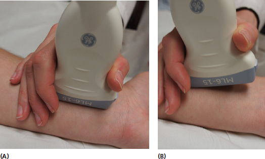
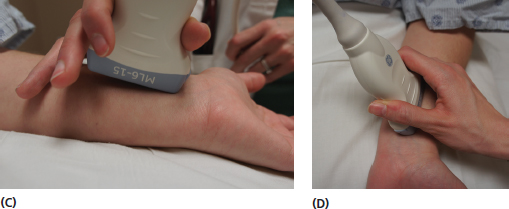
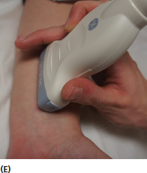
FIGURE 14.12 Pictures demonstrating the use of heel-to-toe and toggling maneuvers with the transducer to eliminate anisotropic artifact. Image (A) shows the transducer in a relatively neutral position with respect to the underlying tissue. Images (B) and (C) show the changes in position in a heel-to-toe rock. The images in (D) and (E) show the changes in position in toggling. These maneuvers are designed to change the direction of the incident beam to create an incident angle to as close to 90° as possible to the object being observed.
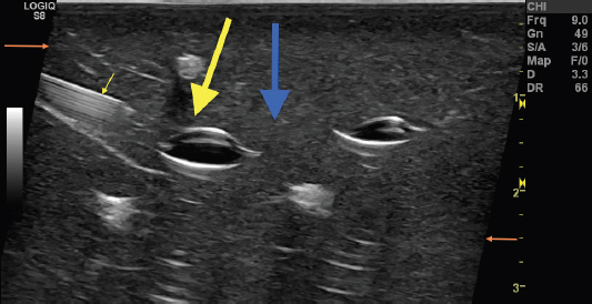
FIGURE 14.13 Sonogram of an in-plane view of a needle (small yellow arrow) using directional change or “beam steering” to change the angle of incidence of the sound waves. This technique allows the examiner to maintain even contact on the skin with the transducer but alters the beam in a favorable direction to increase the angle of incidence to the needle. The large blue arrow indicates the direction of the incident sound waves without this feature. The large yellow arrow shows the direction of the incident sound waves with this feature activated. The change in direction of the margins (orange arrows) indicates the beam steering is activated. Altering the beam to create a more perpendicular approach in relation to the needle position allows for better needle visualization.
The needle should not be advanced if the tip is not visualized. Other maneuvers that can help to visualize the needle tip include jiggling the needle tip back and forth and rotating the needle bevel. When jiggling, the needle is rapidly moved back and forth in relatively small amounts. This movement often increases conspicuity of the tip. Rotating the needle will often help identify the tip because of the asymmetric shape of the bevel.
With out-of-plane orientation the needle is generally easier to visualize, however, only a cross-sectional view is seen. Caution must be used with this approach because the needle appearance is roughly the same regardless of the position of the needle tip (Figure 14.14). The tip is confirmed by the first appearance of the hyperechoic dot as the needle is advanced into the tissue field. In situations where the tip appears at the incorrect depth, the needle should be partially withdrawn and readvanced to the appropriate depth.
Needle reverberation artifact can distort the image of the needle (Figure 14.15). This occurs as a result of the incident sound beam bouncing back and forth between the transducer and the high impedance needle (Figure 13.7). Understanding of this artifact can prevent confusion with this distorted image.
Documentation of the ultrasound-guided procedure should, at a minimum, include an image of the tissue target. An image showing the needle in the proper position is preferable. There should also be documentation of the need for the procedure including an explanation of the need for ultrasound guidance. Becoming proficient at ultrasound guidance requires practice. Using objects such as turkey breasts with placed targets or practice tools such as Blue Phantoms (Figure 14.16) can enhance skills before performing injections in live clinical situations.
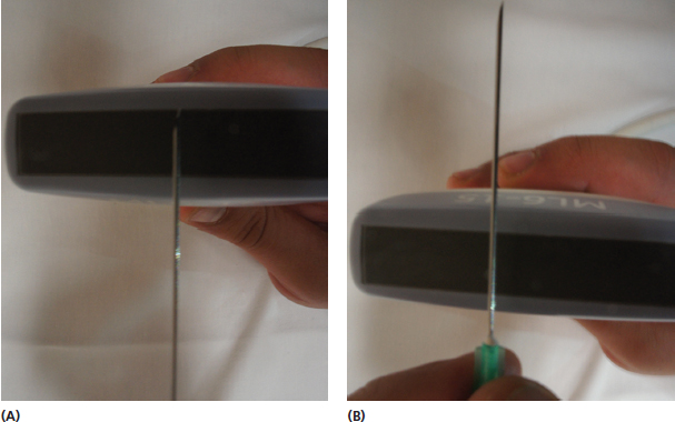
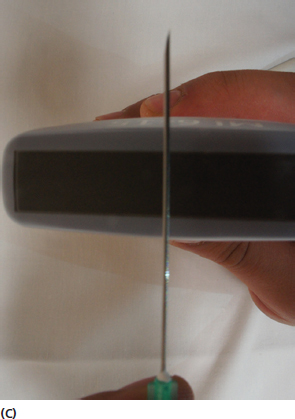
FIGURE 14.14 Pictures demonstrating the potential out-of-plane position of a needle relative to the transducer that all display the same ultrasound image (A)–(C). All three positions will appear as a single hyperechoic dot. For this reason, caution must be used to maintain the location of the needle tip when using the out-of-plane orientation.
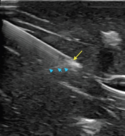
FIGURE 14.15 Sonogram demonstrating needle reverberation artifact. The needle is shown in in-plane view. The needle tip is identified by the yellow arrow and the reverberation artifact is identified by the blue arrowheads. It is important to recognize what portion of the image represents artifact for reliable needle placement.
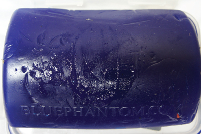
FIGURE 14.16 Picture of an example of a commercial practice tool that can be used to practice guided injections.
REMEMBER 
1) Preprocedure scanning should always be performed to assess for any undesirable areas and plan the depth and precise location of the target.
2) The transducer should be positioned so that the direction of the incident sound waves is perpendicular to the needle as much as possible to minimize anisotropic artifact.
3) In-plane needle orientation is generally preferable to visualize the advancement of the needle tip. When out-of-plane orientation is used, great care is needed to establish when the tip of the needle first arrives in the field.
Related posts:
Stay updated, free articles. Join our Telegram channel

Full access? Get Clinical Tree


