Segmental Anatomy of the Hepatic Parenchyma
An understanding of the segmental anatomy of the liver is fundamental to modern radiological investigation and surgical management of hepatic malignancy (Figure 7-1). The classification was first described in 1957 by the French surgical anatomist Couinaud, and later popularized by Bismuth and is globally recognized.1 The eight hepatic segments are divided into those constituting the right hemiliver (segments V–VIII), the left hemiliver (segments II–IV), and the caudate lobe (segment I). The right and left hemilivers are separated in the functional midline by the plane of the principal fissure between the gallbladder fossa and the inferior vena cava (IVC) (Cantlie Line). This plane is defined by the course of the middle hepatic vein, and has no external markings. In the left lobe of the liver, the plane formed by the umbilical fissure divides the left lateral sector (segments II and III) from the left medial sector (segment IV). The medial sector is divided into segments IVA superiorly and IVB inferiorly. In the right lobe of the liver the plane formed by the right hepatic vein and the IVC divides the right anterior sector (segments V and VIII) from the right posterior sector (segments VI and VII).
Figure 7-1. The segmental anatomy of the liver with the tributaries of the portal vein. (Ellis H. Anatomy of the liver. Surgery (Oxford). 2011;29(12):589–592.)
 Vascular Anatomy
The inferior vena cava courses to the right of the aorta in the retroperitoneum. Prior to ascending posterior to the liver, the IVC lies posterior and lateral to the duodenum and head of the pancreas. The retrohepatic portion of the IVC lies on the posterior surface of the right lobe of the liver, and ascends to the central tendon of the diaphragm behind the bare area of the liver, prior to entering the right atrium. There are three major hepatic veins that enter directly into the inferior vena cava at the superior surface of the posterior liver (Figure 7-2). The right hepatic vein is the shortest of these and lies in the plane dividing the right hemiliver into the anterior and posterior sectors. The length of the right hepatic vein is typically only 1 cm. The middle hepatic vein lies in the plane separating the liver into the right and left lobes (aka, portal fissure, Cantlie line), and commonly joins the left hepatic vein outside the liver parenchyma to enter the IVC as a common trunk, although it may drain directly into the vena cava.1 The left hepatic vein lies in the umbilical fissure separating the left liver into segment IV and the left lateral sector (segments II and III) and has a relatively long extrahepatic course. As described above, the left hepatic vein typically, though not always, joins the middle hepatic vein prior to entering the vena cava.
Figure 7-2. Hepatic veins. Transverse diagram of the liver shows the right hepatic vein (RHV), middle hepatic vein (MHV), and left hepatic vein (LHV) draining into the retrohepatic inferior vena cava (IVC). The hepatic veins divide the liver into Couinaud system segments as indicated.
The proper hepatic artery arises from the common hepatic artery after branching of the gastroduodenal artery and ascends superiorly toward the liver in the lateral free edge of the lesser omentum with the common bile duct and portal vein, the portal triad. Typically the hepatic artery lies anterior to the portal vein and medial to the bile duct in this region. The hepatic artery then divides into branches that supply the right and left liver at the level of the hepatic hilum. The right hepatic artery typically follows a very short extrahepatic course before entering the hepatic parenchyma, where it further divides into right anterior and posterior sectoral branches. The cystic artery supplying the gallbladder arises from the right hepatic artery. The left hepatic artery follows a longer extrahepatic course where it runs to the base of the umbilical fissure. The left hepatic artery then gives off a branch to segment IV known as the middle hepatic artery, and then enters the left lateral segment to supply segments II and III. The caudate lobe (segment I) is also typically supplied by branches of the left hepatic artery.
There are several common anatomic variants of hepatic arterial anatomy that are worth noting. The right hepatic artery may arise directly from the superior mesenteric artery, in which case it is described as being a replaced right hepatic artery. Alternatively, an accessory right hepatic artery may arise from the same location. A replaced right hepatic artery can be identified as a pulsatile structure ascending to the right of, and posterior to, the common bile duct within the portal triad. Similarly, a replaced or accessory left hepatic artery may arise from the left gastric artery and run through the gastrohepatic ligament to supply the left lobe of the liver. Anomalous right hepatic arterial anatomy is present in 10–20% of patients, while anomalies in the course of the left hepatic artery are present in 7–18% of patients.2
The portal vein arises from the union of the superior mesenteric and splenic veins posterior to the neck of the pancreas. The portal vein then ascends toward the liver as the most posterior structure of the portal triad. The portal vein branches into segments supplying the left and right lobes of the liver at the hilum. The course of the portal vein follows that of the hepatic arteries within the liver, and the branch points of the portal triads within the liver define the hepatic segments.
 Biliary Anatomy
Within the liver, the bile ducts follow the course of the hepatic arterial and portal venous branches within portal triads. The extrahepatic right and left ducts join at the hepatic hilum to form the common hepatic duct. The common hepatic duct descends to the right of the hepatic artery and anterior to the portal vein. Typically, the right hepatic artery passes posterior to the common hepatic duct, but an important variant is passage of the right hepatic artery anterior to the duct. The common hepatic duct is joined by the cystic duct, which drains the gallbladder, at which point it is known as the common bile duct. The level of union between the cystic and common hepatic ducts can be highly variable. While the classic anatomy is for the cystic duct to enter the common duct obliquely on the right, common variants include a cystic duct that runs parallel to the common duct for a variable course prior to union, and a cystic duct that spirals posteriorly to the common duct before entering on the left. Inferiorly, the common bile duct passes posterior to the pancreas where it is joined by the pancreatic duct to form a common channel draining into the duodenum. The blood supply to the common bile duct is via the hepatic artery and typically courses in the 9 o’clock and 3 o’clock positions. It should be noted that anomalies from the “typical” pattern described above are frequent and must always be considered during surgical dissection.
 Gallbladder
The gallbladder lies in a fossa on the inferior surface of the liver between segments IV and V. Typically, the gallbladder is completely extrahepatic with a fibrous attachment to the liver bed known as the cystic plate. The gallbladder may occasionally be intrahepatic, that is, surrounded by varying degrees of hepatic parenchyma, or it may be attached to a longer gallbladder mesentery. The gallbladder comprises the fundus most superiorly, body, and neck (or infundibulum). The cystic duct arises from the gallbladder neck and courses medially to join the common hepatic duct, most commonly in an angle to the lateral surface of the hepatic duct. The cystic duct may run parallel to the common hepatic duct before joining, however, and it may spiral around the hepatic duct, prior to entering. There are less common variants in which the cystic duct may enter the hepatic ductal confluence, or into branches of the right or left hepatic ducts. The blood supply to the gallbladder is the cystic artery, which is typically a branch of the right hepatic artery. The typical location for the cystic artery is within the triangle of Calot, the borders of which are the cystic duct inferiorly, the liver bed superiorly, and the common hepatic duct medially.
NORMAL APPEARANCE OF US
The normal liver is homogeneous in appearance. The echo-genicity of the liver should be slightly greater than that of the cortex of the right kidney.3 Distinguishing portal veins from hepatic veins within the liver parenchyma may be somewhat of a challenge to the novice ultrasonographer. The distinction can be made by the echogenicity of the vessel walls (Figure 7-3). Portal veins typically have hyperechoic walls (as they are invested by Glisson capsule), and thus appear bright, while hepatic veins do not have reflective walls.4 Once the hepatic and portal veins are identified, the ultrasonographer can define the various segments of the liver as defined by their relation to the hepatic venous and portal venous structures as described above. Intrahepatic ducts, when normal in diameter, are not visualized on transcutaneous US.
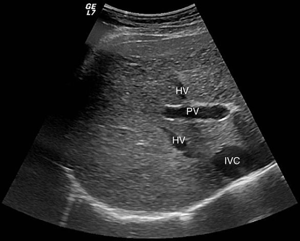
Figure 7-3. Hepatic veins (HV) and inferior vena cava (IVC) are anechoic structures with very thin walls. The portal vein (PV) has echogenic walls that appear brighter on sonographic examination.
With the patient in a fasting state, the gallbladder is typically anechoic with thin walls. Normal gallbladder diameter is typically 3–4 cm, with length up to 10 cm.3 An anatomic aid in identifying the gallbladder includes the main lobar fissure of the liver, which appears as a linear echogenic structure and points toward the gallbladder neck. In addition, the hepatic artery can sometimes be seen anteromedial to the portal vein with the common bile duct anterolateral to the portal vein, forming the so called “Mickey Mouse” sign (see Figure 7-4).5 The normal thickness of the gallbladder wall in the fasting state is less than 3 mm.6,7 If the patient is not in the fasting state; however, the gallbladder will be contracted, which may appear as wall thickening. The normal size of the common bile duct is dependent upon the patient’s age, as the CBD is known to dilate over time.8 Normal CBD diameter is considered to be up to 6 mm, although this figure may need to be revised upward in the elderly (Figure 7-5). An upper limit of 8 mm has been suggested as appropriate in patients over 50.9 Another important consideration is the postcholecystectomy patient as the CBD typically dilates after cholecystectomy.10,11 A diameter of up to 10 mm has been suggested as appropriate in the postcholecystectomy setting,9 but larger diameters can be seen in the absence of other pathology (Figure 7-6).
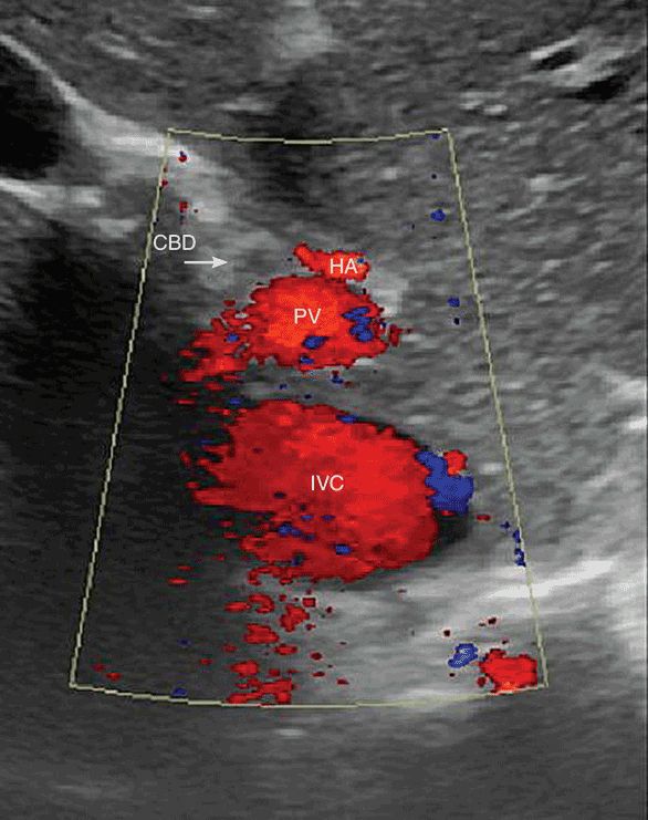
Figure 7-4. The “mickey mouse” sign is made up of the three portal structures. The left ear is the hepatic artery (HA), the right ear (at the arrow tip) is the common bile duct (CBD), and the portal vein is the face.
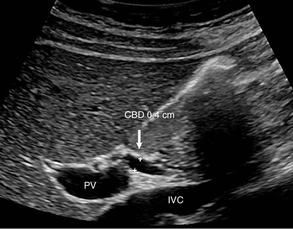
Figure 7-5. Long axis view of the portal vein (PV) demonstrates the normal common bile duct (CBD). The PV can be seen coursing toward the porta hepatis with a portion of the nondistended CBD above. The inferior vena cava (IVC) is seen immediately below.
Figure 7-6. Ultrasound of a patient 1 year postcholecystectomy. The common bile duct is dilated to compensate for an absent gallbladder. This is a normal duct variant postcholecystectomy. Dilated ducts are also seen in older patients without a cholecystectomy.
SCANNING TECHNIQUES
 Transabdominal US
Transabdominal US of the liver, gallbladder, and biliary tree is typically performed with a 2.5–5.0 MHz sector or convex probe. Ideally the patient will be fasting to minimize bowel gas and insure a physiologically distended gallbladder. The scan should begin with the probe placed longitudinally along the right costal margin, so that the posterior right lobe of the liver and the right kidney can be visualized. The depth of penetration of ultrasound waves can be adjusted and should be such that the posterior right lobe is at the bottom of the screen.12 The probe is then placed in a transverse plane below the xiphoid process. The patient is asked to hold his breath, to allow the diaphragm to push the liver down toward the probe, and the probe is angled cephalad to visualize the superior portion of the liver. The junction of the hepatic veins with the inferior vena cava can be seen only through this window. The probe is then moved caudally, while remaining in the transverse configuration. At this point the left portal vein can be visualized as a tubular anechoic structure with hyperechoic walls. The left portal vein should be the only tubular structure visualized within the liver on this view. The presence of other structures suggests intrahepatic biliary dilatation. The probe is then moved further in the caudal direction along the right costal margin. The portal vein as it enters the liver can now be seen, and again should be the only tubular structure visualized. The presence of another tubular structure, the so-called “shotgun” sign,13,14 indicates extrahepatic biliary ductal dilatation. The probe is then moved further along the costal margin of the ribs until the gallbladder can be visualized, which will appear as an anechoic round structure inferior to the portal vein, and then along the costal margin past the gallbladder to examine the right posterior sector.
After the right posterior sector has been examined, the probe is returned to the subxiphoid position, this time in the longitudinal configuration. The probe is slid caudally along the costal margin as described above. This sweep of the probe will allow visualization of the right, left, and caudate lobes, the aorta, and the inferior vena cava. The scan should progress from the xiphoid until the image has moved past the liver to the right kidney.
After examination of the liver has been completed, attention is then turned to the gallbladder, which is seen in the longitudinal plane at the level of the supine patient’s elbow just below the costal margin. The gallbladder will appear as an anechoic, ovoid structure with a tapering neck (Figure 7-7). After thoroughly examining the gallbladder in the longitudinal plane, the probe is rotated to the transverse position without losing contact with the patient’s skin. After passing the probe through the gallbladder several times, the patient is placed in the left lateral decubitus position and the gallbladder is reimaged using the technique above. Decubitus positioning of the patient will cause stones to move into the gallbladder fundus, aiding in visualization.
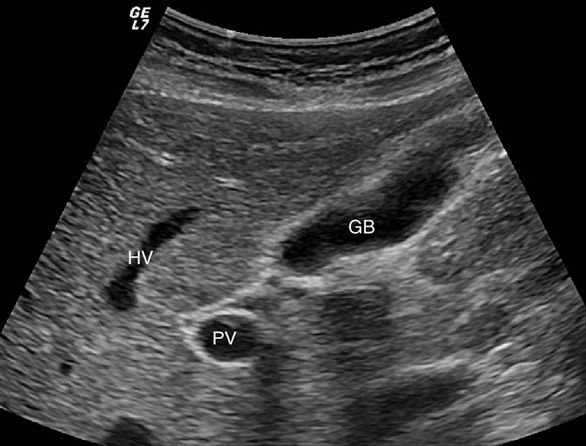
Figure 7-7. Long axis view of normal gallbladder (GB). The main lobar fissure is seen between the GB neck and the right portal vein (PV).
Visualization of the common hepatic duct is aided by having the patient in a 45 degree, right side up position. The probe is placed halfway down the costal margin in the transverse plane. After identification of the portal vein, the probe is rotated to the transverse position, again without losing contact with the patient’s skin. The portal vein will change from a horizontal structure to a circle as the probe rotates. The common hepatic duct will come into view as a tubular structure anterior to the portal vein. Measurement of the common hepatic duct should be from inside wall to inside wall (Figure 7-8).3
Figure 7-8. Common hepatic duct is seen here as a tubular structure anterior to the portal vein (PV). The common duct diameter is measured from inside wall to inside wall.
THERAPEUTIC MANEUVERS
Intraoperative US plays a pivotal role in hepatic surgery, including detection and localization of lesions and planning of hepatic resection. Ultrasound is essential when performing liver-directed therapy for resection or ablation. Although modern cross-sectional imaging such as CT scans and MRIs are highly sensitive, there is still an incidence of additional lesions found by intraoperative ultrasound that are not visualized by preoperative imaging. This incidence can range up to 20% of patients.
IOUS allows evaluation of the relationship between tumor and the hepatic veins, thus allowing for determination of the amount of liver parenchyma that must be resected. Such determination is particularly important in patients with cirrhosis, in whom it is critical to leave an adequate liver remnant postoperatively. In this setting, IOUS allows greater use of segmental resection rather than formal anatomic lobectomy.42,43 The value of IOUS in operative planning has been demonstrated by reports that have revealed changes in surgical management of hepatic tumors due to sonographic findings in 30% to 50% of operations.17,44–47 Facility with IOUS is particularly crucial when considering laparoscopic liver resection, and is considered a mandatory part of the surgeon’s skill set prior to starting a laparoscopic liver program. In addition to aiding in planning for hepatic resection, IOUS may also detect occult hepatic metastases during colorectal surgery in 5–10% of operations.17,48
US is also widely used for guidance in the ablation of hepatic tumors. Thermal ablation, either with radiofrequency (RF) or with microwave (MW) energy has become an important part of the treatment algorithm for patients with unresectable tumors. These procedures may be performed percutaneously, laparoscopically, or at the time of laparotomy. US has become the ideal method for proper localization of the ablation probes, as it gives real-time information on proper placement. Typically, lesions will become hyperechoic as ablation progresses, although assessment of ablation margins by US is limited. These approaches are highly operator dependent, and require a high degree of facility with US on the part of the surgeon.49
 Intraoperative Ultrasound
Intraoperative US (IOUS) of the hepatobiliary tree can be performed either laparoscopically or via an open approach. The transducers used for IOUS may vary depending on the technique and are typically of higher frequency than employed for transcutaneous ultrasound, generally in the range of 7–8 MHz (Figure 7-9).15–17 The use of such high-frequency probes allows for visualization of subcentimeter lesions. Probes for IOUS are typically either flat or cylindrical. The flat probes provide a wide field of view and are particularly well suited for imaging the liver. Probes with a flexible tip that can be articulated or flexed and extended to allow the user to maintain contact on the curved liver surface for optimal visualization are also particularly useful, especially in the laparoscopic setting.
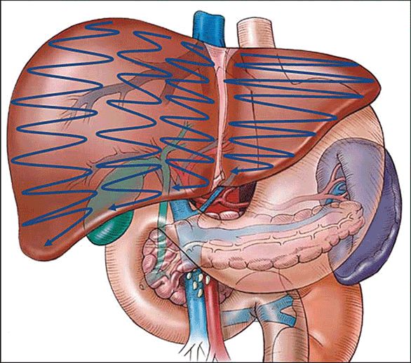
There are two basic techniques utilized. One is the “lawn mower” technique (Figure 7-10) where the ultrasound transducer is swept back and forth across each sector of the liver in a systematic fashion. The second is the “pedicle tracking” technique (Figure 7-11) where the transducer is used to identify the main portal pedicle and then the left and right branches of the portal venous system are followed out through their sectoral and segmental branching points. Ultrasound is then used to map out the location of the hepatic veins as they track and drain into the inferior vena cava. Rotation of the probe in clockwise or counterclockwise direction, along with superior and inferior angulation (“rocking”), allows for structures to be followed and masses outlined with precision.
Related posts:
Stay updated, free articles. Join our Telegram channel

Full access? Get Clinical Tree


