A. X-ray tubes
–X-ray tube voltage in mammography ranges from 25 kV to 34 kV.
–Three-phase or high-frequency generators are used to minimize voltage fluctuations.
–For film–screen mammography, molybdenum (z = 42; K-edge energy 20.0 keV) is the most common target material in the anode because it produces characteristic radiation at optimal energy levels.
–Molybdenum produces characteristic x-rays of 17.9 and 19.5 keV.
–Some commercial x-ray tubes use rhodium targets (z = 45; K-edge energy 23.2 keV), which produce characteristic x-rays with a slightly higher energy.
–Rhodium produces characteristic x-rays of 20.2 and 22.7 keV, which are more penetrating than those of molybdenum.
–Rhodium characteristic x-rays have an energy ~3 keV higher than molybdenum characteristic x-rays.
–Tungsten targets are also available on some machines, which do not produce characteristic x-rays in the mammography range.
–Filters for tungsten targets may be molybdenum, rhodium, or sliver (Z = 47; K-edge energy 25.5 keV).
–The normal focal spot is 0.3 mm, which is much smaller than conventional radiography (1.2 mm).
–The 0.3 mm focal spot uses tube currents of 100 mA.
–The small focal spot (0.1 mm) is used for magnification mammography.
–The small focal spot can tolerate only low currents of ~25 mA.
–A beryllium (Z = 4) x-ray tube window is used to minimize x-ray beam attenuation.
–The heel effect (higher x-ray intensity on the cathode side) is used to increase the intensity of radiation near the chest wall where greater penetration is needed.
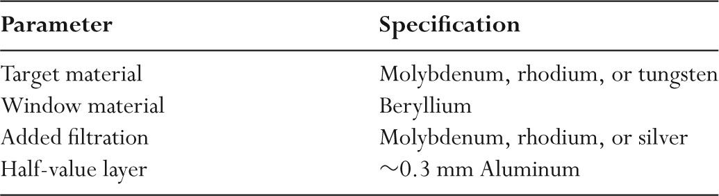
–Table 4.1 shows the physical characteristics of the key components of mammography x-ray tubes.
B. Filtration
–For screen–film mammography, the x-ray energy level that optimizes contrast for an average-sized breast is ~19 keV.
–Lower-energy x-ray photons have inadequate breast penetration and increase dose.
–Higher-energy x-rays photons decrease contrast.
–The optimum mammographic photon energy increases with increasing breast thickness and breast density.
–Filters are used to achieve the optimal photon energies that minimize both high-and low-energy x-ray photons.
–Filters in mammography may be made of molybdenum, rhodium, or silver.
–Filters in mammography are ~30 μm thick.
–Filters remove most bremsstrahlung radiation above the filter K-edge.
–Removal of this higher-energy bremsstrahlung radiation improves contrast.
–All filters remove very low-energy x-rays that contribute only to patient dose.
–Figure 4.1 shows the x-ray spectra from a molybdenum target.
TABLE 4.1 Specifications for a Screen–Film Mammography Unit
–Compared to a Mo filter, a Rh filter transmits more photons between 20 keV and 23 keV.
–Compared to a Rh filter, silver (K-edge 25.5 keV) transmits more photons between 23 and 25.5 keV.
C. Grids
–Scatter to primary ratios in mammography ranges from 0.6 to 1.0.
–Reduced scatter is due to the use of low-energy photons that interact primarily by photoelectric absorption.
–For soft tissue, x-ray photon energies >25 keV would produce more Compton scatter than photoelectric absorption.
–Scatter to primary ratios in mammography are lower than for general radiology.
–Scatter in mammography nonetheless reduces image contrast.
–The importance of scatter increases with increasing breast thickness and increasing x-ray tube voltage.
–Contact mammography is performed using a moving grid.
–Carbon fiber is the most common interspace material for linear grids as aluminum would attenuate too many of the low-energy x-rays used in mammography.
–One manufacturer produces a high transmission cellular (HTC) grid with a honeycomb pattern and an air-interspace material.
–Values for linear grid line densities are ~50 lines per centimeter.
–Mammography imaging systems use grid ratios of ~5:1.
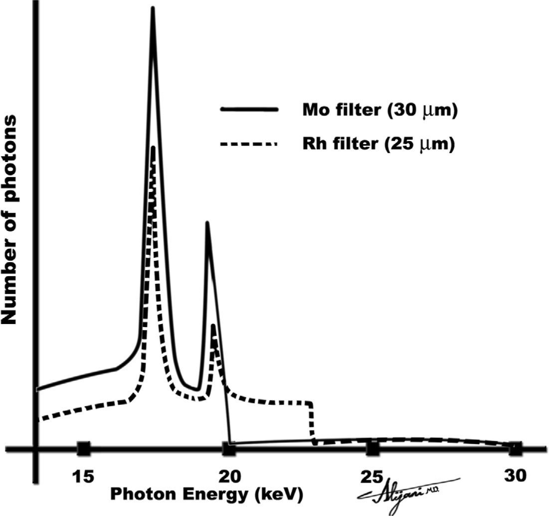
FIGURE 4.1 X-ray spectra from a molybdenum target at 30 kV showing the effect of adding a molybdenum (or rhodium) filter.
–Mammography grids have a Bucky factor (ratio of radiation intensity incident on the grid to that transmitted) of ~2.
–Use of a grid doubles the patient dose relative to nongrid examination.
D. Screen–films
–Rare earth intensifying screens made of gadolinium oxysulfide (Gd2O2S) are used in screen–film mammography.
–Single screens are used, which may incorporate light absorbers to limit screen diffusion and improve resolution.
–Single-emulsion films are used to reduce receptor blur.
–Crossover and parallax effects are eliminated by using a single emulsion.
–X-rays are mainly absorbed at the front of the screen which should be located as close as possible to the film to minimize blur.
–This is achieved by having the film between the x-ray source and screen.
–Mammography films generally have high gradients (>3.0) and, accordingly, low film latitude.
–Limited latitude is acceptable when there is adequate breast compression and the film is properly exposed.
–Mammography films have relatively thick single emulsions, which make them sensitive to processor artifacts.
–Optimal film densities in mammography are between 1.6 and 2.0, higher than in radiography.
–Higher film densities are needed in mammography because this results in the best film contrast.
E. Digital detectors
–Full field of view digital systems are replacing screen–film mammography.
–In 2008, about one third of all mammography facilities were using digital mammography.
–Higher-energy x-ray spectra are used in digital mammography.
–A typical matrix size in digital mammography is 3k × 4k.
–Pixel sizes are ~80 μm, whereas the smallest visible microcalcifications are ~150 μm.
–Photostimulable phosphors with a 50-μm pixel size have also been used to perform digital mammography.
–Digital mammograms may be processed using computer aided diagnosis (CAD) software, which attempts to identify malignant lesions, and microcalcification clusters.
–CAD systems can assign a probability of malignancy for each identified lesion.
–Mammography CAD software has been shown to have sensitivities as high as 90% and can identify lesions missed by radiologists.
–CAD systems can have a high false-positive rate of up to one or two false positives per image.
–CAD has a high accuracy for detection of clusters of microcalcifications.
F. Compression
–Optimal mammography requires the use of breast compression.
–Compression is achieved using radio translucent paddles.
–Compression reduces the thickness of the breast, and as a result reduces breast dose.
–Compression also immobilizes the breast and spreads the breast tissue.
–Lower x-ray tube voltages can be used with compression, which will increase contrast.
–Compression brings the breast closer to the image plane, minimizing image magnification and reducing focal spot blur.
–Compression reduces exposure times, and thus minimizes patient motion blur associated with long exposure times.
–Compression force is normally between 111 and 200 newtons (25 and 45 lb).
–The principal drawback of compression is patient discomfort.
A. Cancer Detection Task
–Mammography is a low-cost and low-dose procedure that can detect early-stage breast cancer.
–Recognition of breast cancer depends on detection of subtle architectural distortion, masses near normal breast tissue density, skin thickening, and microcalcifications.
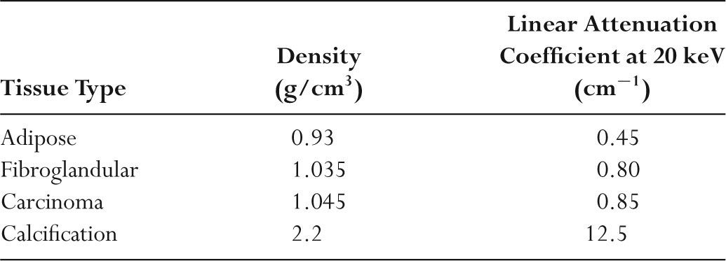
TABLE 4.2 Properties of Breast Tissue
–Microcalcifications are specks of calcium hydroxyapatite [Ca5(PO4)3OH], which may have diameters as small as 0.1 mm (100 μm).
–Detection of microcalcifications is difficult because of their small dimensions.
–Table 4.2 summarizes the key physical properties of the major breast tissues and pathologic conditions.
–X-ray attenuation properties of breast cancer are similar to those of normal fibroglandular tissue.
–The small differences in attenuation between normal and malignant tissue result in low contrast and make cancer detection difficult.
–Mammography imaging systems are designed to maximize image contrast.
–Image contrast in screen–film mammography is improved by use of low photon energies, high film gradients, breast compression, and scatter-removal grids.
B. Contact mammography
–Screening mammography normally includes a craniocaudal and a mediolateral oblique view of each breast.
–Compressed breasts are normally 3 to 8 cm thick, with an average of ~4.5 cm.
–Typical x-ray tube currents are ~100 mA.
–Exposure times are generally longer than ~1 second.
–Exposure times may be up to 4 seconds for dense and/or thick breasts.
–Exposures in excess of about 2 to 3 seconds may introduce motion artifacts.
–X-ray beam half-value layers in mammography are ~0.3 mm Al.
–For a normal compressed breast (4.5 cm), a typical x-ray tube voltage in screen-film mammography is 25 kV.
–Higher tube voltages are used in digital mammography.
–The tube current exposure time product is ~150 mAs.
–Compression results in greater sharpness, less scatter, and reduced patient dose.
–A mammogram requires an air kerma of ~0.2 mGy at the image receptor.
–Table 4.3 summarizes techniques used in contact mammography.
C. Magnification mammography
–Magnification mammography improves visualization of mass margins and fine calcifications.
–Magnification is achieved by moving the breast away from the film using a 15-to 30-cm standoff and keeping the source to image receptor distance constant.
–The geometric principles of magnification are illustrated in Figure 4.2.
–The magnification is the ratio of the source to image receptor distance (SID) to the source to object distance (SOD); magnification is given as SID/SOD.
–A typical SID is 65 cm, and SOD in magnification is 35 cm, so that magnification is normally 1.86.
–Small focal spots (0.1 mm) are essential to minimize geometric unsharpness with tube currents of ~25 mA.
–The breast area that can be imaged in a single magnification radiograph is reduced.
TABLE 4.3 Technique Summary for Mammography
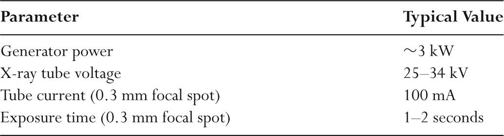
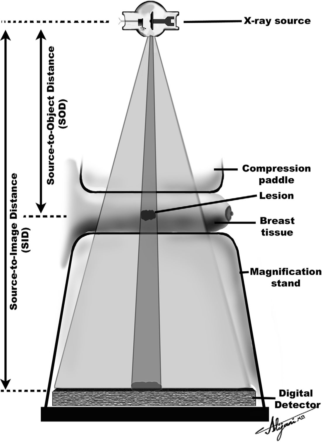
FIGURE 4.2 Geometric principles of magnification in mammography.
–The presence of an air gap reduces the amount of scatter reaching the film and eliminates the need for a grid.
–The absence of a grid reduces the required mAs by ~30%, since there is no loss of primary photons by any grid.
–Compared with contact mammography, reduced x-ray tube currents (i.e., 25 mA) increase exposure times by a factor of about three.
–Longer exposure times markedly increase the chance of patient motion (blur).
D. Viewing mammograms
–High luminance viewboxes and complete film masking are required.
–Viewboxes with luminance values of ~3,000 candelas per square meter (cd/m2) are used.
–Conventional viewboxes are ~1,500 cd/m2.
–Extraneous light decreases contrast perception.
–A magnifying glass should be used to view microcalcifications.
–Viewing rooms should be darkened (<50 lux), and hot lights should be available.
–A digital screening examination and prior examination contain 400 MB of data.
–Viewing digital mammograms requires high quality and high performance monitors.
–Five-MP monitors are essential for viewing digital mammograms.
E. Stereotaxic localization
–Stereotaxic localization has been developed to perform core needle biopsies.
–Digital imaging systems are used for stereotaxic localizations, eliminating time- consuming film processing.
–The matrix size of digital systems is 512 × 512 or 1,024 × 1,024.
–For a 5 cm × 5 cm field of view, the pixel size is 50 to 100 μm.
–Digital systems use a CCD to capture the light from the screen and a 2:1 demagnification of the image via optical lenses or fiberoptic tapers.
–Two views of the breast are normally acquired (±15 degrees from the normal).
–Images of the lesion will shift by an amount that depends on the lesion depth, which permits a three-dimensional localization of the lesion.
–A biopsy needle gun is positioned and fired to capture the required tissue sample.
–Benefits of core needle over open biopsies are a short procedure time, minimal local anesthetic, reduced cost and risk, and no residual scarring of breast tissue.
F. Digital Tomosynthesis
–Compression causes overlapping of the breast tissue, which reduces breast cancer visibility.
–Digital tomosynthesis creates tomographic images that improve lesion visibility.
–A conventional digital mammography imaging chain is used to generate tomographic images.
–Digital tomosynthesis requires full compression to minimize motion artifacts during the long scan times.
–Digital tomosynthesis takes a number of projection images, each at a different angle.
–The x-ray tube moves in an arc around the breast, with projection images obtained at selected angles.
–The total angular movement is 15 degrees, with one image taken every degree, for a total of 15 projection radiographs.
–The total examination time is ~5 seconds.
–The total radiation dose in digital tomosynthesis is comparable to a contact mammogram on a digital system.
–Acquired image data are processed to generate ~45 tomographs, with a nominal slice thickness of ~1 mm.
–Digital tomosynthesis entered clinical practice in Europe in late 2008, and FDA approval is expected in the United States in 2009.
A. Breast cancer
–Breast cancer accounts for 32% of cancer incidence and 18% of cancer deaths in women in the United States.
–The National Cancer Institute estimated that there were ~180,000 new cases of breast cancer in the United States in 2007, including 2,000 males.
–The number of breast cancer deaths was 40,000.
–One in eight women in the United States ultimately develops breast cancer.
–Figure 4.3 shows breast cancer incidence and mortality rates.
–Early detection with screening mammography reduces breast cancer mortality rates by between 15% and 35%.
–The American Medical Association, American Cancer Society, and American College of Radiology (ACR) all recommend screening of asymptomatic women.
–The ACR recommends a baseline mammogram by age 40, biannual examinations between ages 40 and 50, and yearly examinations after age 50.
B. MQSA
–The Food and Drug Administration (FDA) developed the Mammography Quality Standards Act (MQSA) requiring all of the more than 10,000 mammography facilities in the United States to be certified.
–MQSA was passed in 1992, and the final rules became effective April 1999.
–It is against federal law to practice mammography without certification by the FDA.
–To obtain certification, the facility must receive accreditation by an approved body such as the American College of Radiology (ACR).
–The ACR initially developed a voluntary mammography accreditation program in 1987 to improve the quality of screen–film mammography.
–Accreditation is currently based on the five steps listed in Table 4.4.
–Some states (e.g., Arkansas, California, Iowa, and Texas) have mammography accreditation programs that are similar to the ACR program.
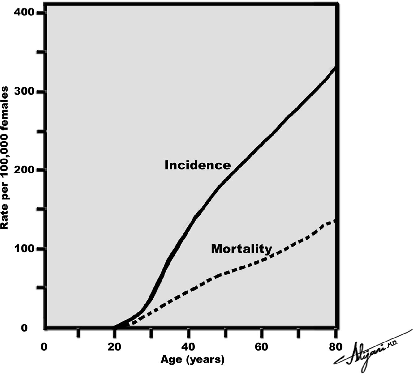
FIGURE 4.3 Breast cancer incidence and mortality.
Related posts:


Stay updated, free articles. Join our Telegram channel

Full access? Get Clinical Tree


