| Metric | Metric definition | Old units | SI units | Conversion factor |
|---|---|---|---|---|
| Exposure | Ionization per unit mass of air | Roentgen (R) | Coulombs/kilogram (C/Kg) | 1 R = 2.58 × 10⁻⁴ C/Kg |
| Air Kerma | Kinetic energy released per unit mass of air | _ | Gray (Gy) 1 Gy = 1 J/Kg | |
| Absorbed Dose | Energy imparted per unit mass | rad | Gray (Gy) | 1 rad = 10 × 10–3 Gy |
| Equivalent Dose | Absorbed dose-weighted for type of radiation | rem | Sievert (Sv) | 1 rem = 10 × 10–3 Sv |
| Effective Dose | Equivalent dose-weighted for relative radiosensitivity of tissues | rem | Sievert (Sv) |
The Radiation Absorbed Dose is purely a physical quantity that describes the absorption of energy by any material, and it does not account for biologic damage in living organisms. The biologically significant consequence of interaction of x-rays is in their ability to ionize atoms, which is the process of removing electrons from atoms (ionizing radiation). The process of ionization has the potential of inducing detrimental effects in biologic tissues by several complex mechanisms that can lead to effects such as DNA single- or double-strand damage, which can lead to carcinogenesis (8). High doses of radiation from certain imaging procedures may also cause skin erythema, epilation, and, in extremely rare cases, dermal necrosis (8, 11). The effects of x-rays and gamma rays on biologic systems and cells have been known from the early years of discovery of x-rays and gamma rays. It has been well established for more than 100 years that the proper use of x-rays and radionuclides in medical imaging requires careful consideration of the physical and biologic aspects of radiation dosimetry.
It is well known that different types of ionizing radiation may induce varying degrees of biologic damage for the same Radiation Absorbed Dose. Therefore, some types of radiation can be more damaging than others for the same Radiation Absorbed Dose in a given tissue. In order to account for this variability, the concept of Equivalent Absorbed Dose, also known as “Equivalent Dose,” is used. Equivalent Absorbed Dose is derived by multiplying the Radiation Absorbed Dose in Gy by a Radiation Weighting Factor (wR) which accounts on a relative scale for the potential biologic effect. For x-ray and gamma radiation used in imaging the numerical value of this conversion factor is unity; therefore, the absorbed dose in Gy is numerically equal to the Equivalent Dose, but the units are now expressed in Sieverts (Sv) to designate the Equivalent Dose. The value for the conversion factor (wR) can be higher than unity for other types of radiation-like neutrons, protons and as high as 20 for alpha particles but these particles are not relevant to diagnostic imaging. Therefore, 1 Gy of Radiation Absorbed Dose from x-rays and gamma rays in any tissue becomes 1 Sv of Equivalent Dose to that tissue. For x-rays and gamma rays, the term “Dose” is commonly used and it represents Radiation Absorbed Dose.
X-rays emitted from modern radiographic equipment produce a highly collimated (spatially restricted) beam much like a spot light which can be directed onto a particular area. While most of the radiation dose is restricted to the tissues within the target region irradiated by the collimated x-ray field, tissues adjoining this region could receive a small fraction of the radiation dose due to x-ray scattering within the body. Additionally, extra-focal or off-focus radiation arising from electrons impinging the anode at locations adjacent to the focal spot within the x-ray tube could also affect regions extending to about a few centimeters beyond the target region. Another source of unwanted radiation arises from leakage of x-ray through the shielding of the x-ray tube. In radiography, the dose from leakage radiation is typically less than 1/1000 of the dose from the primary (useful) x-ray beam intensity and its contribution to the patient dose is considered negligible. Thus, if we consider a series of extremity radiographs, each radiograph will deliver most of the radiation dose to the collimated region and not to the entire body. For example, if a hand radiograph delivers 0.05 mGy to the hand at skin entrance, the rest of the body receives virtually no radiation of any significance. In radiographic and fluoroscopic examinations, for example a chest radiograph, most of the radiation dose is restricted to the collimated region, chest in this example, with the rest of the body receiving substantially reduced radiation dose mostly due to scattering of the primary beam within the body. Hence, in order to assess the risk from partial body irradiation as practiced in diagnostic x-ray imaging, the concept of Effective Dose was developed. Conceptually, for x-rays and gamma rays, the Effective Dose is the mean absorbed dose resulting from a uniform irradiation of the entire body that is associated with the same total radiation risk detriment as that from the irradiation of just a part of the body (12). The Effective Dose metric enabled calculation of the total body radiation dose equivalence from a single or a series of radiographic examinations.
The Effective Dose (HT) is estimated as:
where DT is the dose equivalent to the tissue T, and wT is the weighting coefficient for that tissue (13, 14). The weighting coefficient is different for various tissues depending on their radiosensitivity. Figure 28.1 shows the tissue weighting factors for some of the organs and tissues recommended by the International Commission on Radiological Protection (ICRP) (14). The above calculation must be performed for each tissue that receives a substantial amount of radiation to yield the Effective Dose.
Figure 28.1 Tissue weighting factors (wT) recommended by the ICRP for some of the organs and tissues (ICRP Report No. 103, 2007). The remainder of the tissues (13 for each sex) include adrenal glands, extrathoracic tissue, gall bladder, heart, kidneys, lymphatic nodes, muscle, oral mucosa, pancreas, small intestine, spleen, thymus, and prostate (for men) or uterus/cervix (for women).
For example, a hypothetical CT examination of the head to a one-year-old infant may deliver about 20 mGy absorbed dose to the midsection of the tomographic slices, but this may translate to an Effective Dose of only about 2 mSv or less as organs and tissues in the imaged region receive most of the dose, which is about 10% or lower than the absorbed dose at the examination site. The Effective Dose from pediatric imaging studies has been reported in many publications (15–21). The Effective Dose enables a comparison of the radiation received from various examinations and it also provides a means to compare this radiation with that received from other sources, such as the natural background radiation. The Effective Dose an individual receives from natural background sources is about 3.0 mSv per year. Therefore, in the above example of a head CT examination, the resulting effective x-ray dose is considered equivalent to about 8 months of natural background radiation. CT examinations represent the highest effective dose in the spectrum of the radiographic examinations. By comparison, a plain high-resolution radiographic examination of the hand, may impart a dose of about 0.05–0.10 mGy at skin entrance, which corresponds to less than 0.01 mSv of Effective Dose. This Effective Dose is about the same as an individual receives in one day of natural background radiation. Linet et al. from the National Cancer Institute have published a comprehensive review of Effective Dose levels to children and adults from diagnostic imaging procedures with tables listing the estimated Effective Dose for various examinations (22). Importantly, the Effective Dose for common pediatric imaging procedures is reported for various ages from newborn to adults in increments of about five years. The risks from such procedures are also discussed in this publication.
The Effective Dose model has been used widely for assessing radiogenic risk (23–27). However, caution must be exercised in the interpretation of its significance (28). The use of this metric as an index of risk or detriment from radiation has been the subject of criticism and controversy (28, 29). It is important to note that the Effective Dose can be useful but it also has limitations as a metric of radiogenic risk. The estimation of the Effective Dose requires measurements and assumptions that are subject to uncertainties in the measured dose and in assumptions made for its calculation. First, it requires the measurement of the Radiation Absorbed Dose, which is almost always estimated and not directly measured for the individual patient. Additionally, the irradiated volume must be known, and this is subject to uncertainties primarily due to body size, which is problematic between large and small patients. This presents a substantial challenge due to the large variation in size in the pediatric population. The dose imparted to each organ or tissue can vary with the position of the x-ray beam and as a result, the organ dose at each of these locations is also subject to considerable uncertainty. Most importantly, even if we assume that the widely used values of the weighting factors for each organ or tissue are accurate in representing radiogenic risk, these risk weighting factors are intended for the general population and they do not account for the radiosensitivity of the individual patient. Moreover, the risk weighting factors do not account for age and this is particularly a problem in estimating the risk to the pediatric patient. The Effective Dose can be instructive in the understanding of the relative risks between different radiologic examinations and also in estimating the radiogenic risks to a population of human subjects who undergo imaging procedures. The Effective Dose becomes more problematic when it is applied to the individual patient. Unfortunately, the Effective Dose is often reported for individual patients without adequate explanation of the aforementioned limitations of this radiation dose descriptor. The Effective Dose sometimes is also reported without a clear differentiation between this dose metric and the physical quantity of dose, the Radiation Absorbed Dose, as noted by Brenner (28).
The x-ray image
The radiographic image is the recorded shadowgram of x-rays after they are transmitted through the body. Typically, about 5% of all x-rays incident on abdomen as an example are transmitted, and are available for detection but this can vary greatly depending on the body part thickness. The rest of the x-rays are either scattered (by the Compton and coherent effect) or are completely absorbed (photoelectric effect) by the body tissues. The difference in absorption and scattering characteristics of the tissues along the x-ray beam path and consequently the spatial variations in the number of x-rays, and its energy transmitted through the body is responsible for the recorded contrast on the radiograph. The absorption and scattering characteristics of tissues are dependent on their effective atomic number and density. For example, the high absorption of x-rays by bone produces a strong shadow because of its higher effective atomic number and density compared to soft tissues, which are less dense and their effective atomic number is much lower. The density of bone typically ranges from 1.2 g/cc for trabecular bone to 1.9 g/cc for cortical bone, and that for muscle and fat tissue is 1.05 g/cc and 0.90 g/cc, respectively. The high effective atomic number of bone is due to its calcium content, which contributes to an abundance of electrons that are strongly bound to its nucleus, favoring absorption by the photoelectric effect compared to the loosely bound electrons of the elements constituting soft tissue. Therefore, the contrast mechanism between soft tissues and bone is due to the difference in the density and the atomic number and this is a classic example of the radiographic process. Contrast between soft tissues is also dictated by the same mechanism, but the differences are much smaller than between soft tissue and bone. Fat has a lower effective atomic number, which means that fat consists of relatively light elements such as hydrogen and carbon, while muscle and other nonfat soft tissues contain heavier elements such as oxygen and nitrogen. Hence, fat is less absorbing of x-rays than muscle because of its lower density and effective atomic number. The differential absorption property of x-rays by tissues of various compositions (subject contrast) is an essential element of radiographic image formation. These differences in contrast are commonly referred to as “densities” in the radiograph. The terms bone density, fat density, air density are commonly used. It is important to note that due to the combination of differences in the effective atomic number and density among certain tissues, they may not exhibit different x-ray contrast despite the fact that the two tissues may be very different histologically. Moreover, the tissue density alone may not account completely for the contrast in the radiologic image (30). Because of the similarity in x-ray attenuation, and interference from overlapping tissues, discrimination between soft tissues is challenging in conventional radiography and the level of this detail is highly dependent on the particular tissue and physiologic process. Improved visualization of soft tissues is possible with CT because of its tomographic capability, and even higher contrast between soft tissues is attained with MRI because of its high sensitivity to magnetic properties of tissues combined with tomographic imaging. Other factors determining radiographic image quality include the spatial resolution, quantum mottle, detector “noise,” and artifacts that will be discussed in the following sections.
Image contrast
Contrast (or contrast discrimination) is the ability of the imaging system to record subtle differences in x-ray absorption among tissues. Contrast resolution is profoundly affected by the energy of the x-ray beam, which is selectable by the operator by adjusting the kVp. Generally, as the energy of the x-ray beam increases by increasing the kVp, the ability of the beam to penetrate through dense or thick tissues improves. In general, the use of a relatively high kVp is desirable until the point that contrast loss due to high energy begins to degrade. This strategy is highly dependent on the particular imaging task and the optimal kVp is different for imaging various parts of the anatomy. In general, lower kVp is used for imaging of infants (about 60 kVp or lower) and higher kVp is used for older children.
Contrast is affected by interference from scattered x-rays in the body reaching the detector, the number of x-rays detected, and the ability of the x-ray detector to record the image without additional degradation or “noise.” Radiologic technologists are aware of the dependence of contrast on the energy of the x-ray beam and apply the appropriate energy setting expressed in kVp for each type of examination. The interference from scattered x-rays is particularly destructive on contrast, and it is an important issue in body imaging. The number of scattered x-rays is much lower in extremity imaging due to the small volume of soft tissue, and generally the contrast in extremity skeletal images is very high. X-ray scatter increases dramatically with body thickness and with the area of irradiation. Fortunately, its effect on contrast is not as dramatic in the body imaging of small children (up to the age of about 12 years) and it has an even lesser effect on extremity imaging where the thickness of tissue is small and the magnitude of x-ray scatter is low.
The number of detected x-rays is a critical factor affecting contrast discrimination. The kVp and the product of tube current and exposure time (mAs) in combination affect the information density of the image, that is the number of x-rays detected per unit area that form the image. This affects the statistical quality of the image or the degree of graininess in the image.
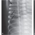
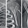
Generally, the contrast improves if more x-rays are detected and this can be accomplished with a more efficient detector or with higher radiation dose. Typically, radiographic detectors such as the now obsolete film-screen cassettes and the more recent digital detectors detect about 60–90% of the incident x-rays; the nonintercepted x-rays pass through the detection system without interaction. A major limitation in discerning subtle differences in subject contrast arises from the limited number of x-rays detected. This effect is called “quantum noise,” or “quantum mottle,” which gives the image a grainy appearance, a major factor contributing to degradation in the diagnostic quality of x-ray images. Quantum mottle tends to obscure small differences in attenuation between tissues and, therefore, it can contribute to missed lesions. Figure 28.2 shows an example where an “elbow” test phantom is imaged at three different settings. While the kVp is identical (60 kVp), the mAs and the distance between the x-ray source and the detector were varied. The number of x-ray photons per pixel is increased from (A) to (C), resulting in improved skeletal image quality. It is relevant to note that for a fixed kVp, increasing the mAs and/or reducing the distance between the x-ray source and the detector would increase the absorbed dose to the patient and increase the number of x-rays per pixel. Compared to the panel (C), the “fracture” (marked by arrows in each panel) is barely visible in panel (A). The degradation of the image is due to the lower statistical quality of the image, or quantum mottle. Good examples of the effect of quantum noise, analogous to the simulation above, can be observed in photographs taken at low light levels. Careful observations of these images reveal a snow-like grainy appearance due to the low number of light photons detected by the camera image sensor. Outdoor daylight pictures rarely exhibit quantum mottle effects because of the abundance of light (number of photons) that reach the camera image sensor. In x-ray imaging, increasing the number of detected x-rays, or increasing the efficiency of the detector, will result in lower quantum mottle and improved contrast, and better discrimination of radiographic densities among different tissues. The downside of aggressive dose reduction is in increasing the probability of missing an abnormality as demonstrated in Figure 28.2.
Figure 28.2 Images of an elbow phantom with a fracture marked by arrow. The number of x-ray photons per pixel is progressively increased from left to right. While all images were acquired at 60 kVp, the mAs and source-to-detector distances were: (A) 0.5 mAs, 74 inches; (B) 4 mAs, 40 inches; and (C) 16 mAs, 40 inches. Reducing the number of x-ray photons per pixel, for example in A, causes increased image noise, resulting in reduced visibility of the fracture.
Figure 28.3 shows an experimental radiographic example of “lesions” in a homogenous background by acquiring three images of a contrast test object at three different exposure levels. All images were acquired at 50 kVp, image A at 16 mAs, image B at 5 mAs, and image C at 0.5 mAs. Therefore, image A was acquired with three times the dose of image B and 32 times the dose of image C. The lesions from top to bottom of each column (1–8) have the same diameter and the diameter of each lesion decreases moving horizontally from column 1 to column 8. The contrast of each lesion decreases progressively from the top row to the bottom row. It can be clearly seen that visualization of lesions decreases progressively as we move from the upper left to the lower right of this image. It is important to note that the lesions from top to bottom in each column (1–8) become progressively invisible not because of size but due to their decreasing contrast. This can occur because its composition or thickness is low compared to the background. Additionally, improper selection of kVp and high x-ray scatter can contribute to reduction in contrast. Image A exhibits the best contrast (more lesions are visible) compared to image B and C owing to the higher dose and good x-ray photon statistics (number of x-rays per unit area). In image C, the photon statistics are poor due to the relatively low dose and the image has a noisy appearance. An acceptable image would probably be image B or perhaps an image with an exposure between images A and B. The reason for not opting for the “best” image quality is that the dose for such an image may be too high and the gain in diagnostic image quality may not be substantial. This situation is very common in radiography where soft tissue or even skeletal lesions may not be visualized because of lack of contrast and not because of size.
Figure 28.3 Images of a contrast-detail phantom containing details or “lesions.” The lesions from top to bottom have the same diameter and the diameter of each lesion decreases from left to right. Within each column, the contrast of the lesion reduces from top to bottom. All images were acquired at 50 kVp, and the mAs were: (A) 16 mAs; (B) 5 mAs; and (C) 0.5 mAs. It is important to note that the lesions from top to bottom in each column become progressively invisible not because of size but due to their decreasing contrast. Image A exhibits the best contrast (more lesions are visible) compared to images B and C owing to the higher dose and good x-ray photon statistics (number of x-rays per unit area).
Image spatial resolution
Spatial resolution refers to the ability of an imaging system to distinguish (resolve) two closely spaced objects. High-resolution x-ray images allow better definition of small and closely spaced structures such as the borders of a “hair line” fracture of fine trabeculae in bone. The term “sharpness” is also used to describe the clarity of a border; but sharpness does not have a quantitative descriptor and is used for subjective judgment. However, spatial resolution can be measured very accurately by objective means.
Figure 28.4 shows a radiographic image of a resolution test object used to assess the spatial resolution of radiographic systems. In this case, the image of the test object was acquired using a portable wireless digital flat-panel radiographic system. The converging lines are very thin x-ray absorbing lines with specified spacing that becomes progressively smaller as they converge. As the lines converge, the number of lines per unit length referred to as the spatial frequency in line pairs per millimeter (lp/mm) increases. The maximum spatial resolution of a radiographic system is determined by the spatial frequency (lp/mm) at which the individual lines appear merged or blurred. In x-ray imaging, depending on the radiographic system, the maximum attainable spatial resolution can range from 1.0 to 20.0 lp/mm. In this case, the lines converge at about 3.5–4.0 lp/mm and, therefore, this is the limiting spatial resolution for this x-ray imaging system.
Figure 28.4 A radiographic image of a test object used to assess the spatial resolution of radiographic systems. The converging lines are very thin x-ray absorbing lines with specified spacing that becomes progressively smaller as they converge. As the lines converge, the number of lines per unit length referred to as the spatial frequency in line pairs per millimeter (lp/mm) increases. The maximum spatial resolution of a radiographic system is determined by the spatial frequency (lp/mm) at which the individual lines appear merged.
High spatial resolution is very important for the detection of subtle skeletal abnormalities, particularly in infants, and, for this reason, imaging systems for skeletal surveys (SSs) are optimized for high spatial resolution. However, imaging at high spatial resolution generally requires higher radiation dose and, therefore, careful balancing between spatial resolution, contrast, and dose is very important. In other imaging tasks, such as abdominal or pelvic imaging, planar radiography is limited by the anatomic complexity and overlapping tissues and organs. Therefore, high radiographic spatial resolution may be of limited usefulness if the anatomic complexity is the limiting factor.
Physiologic motion and voluntary movement
Physiologic motion, such as breathing, peristalsis and voluntary body movement can have a detrimental effect on the spatial resolution of the radiographic image. Amateur and professional photographers are familiar with the consequences of motion of the subject in their images. In radiography this presents a particular challenge with infants who cannot be asked to hold their breath or hold still during the x-ray exposure. Fortunately, modern x-ray generators have the ability to take extremely short exposures, in the order of one millisecond if necessary in order to “freeze” motion. A short exposure time in conjunction with specially designed body immobilizing devices works quite well for imaging of infants. The study of physiologic function or combined physiologic and anatomic imaging, where the path of administered contrast medium is monitored, is performed by electronic imaging means where x-ray imaging is performed in real time and recorded by a digital x-ray video system (fluoroscopy) and is discussed later in this chapter.
X-ray detection systems
The physical characteristics of the x-ray detection system have a profound effect on radiographic image quality and radiation dose to the patient. Proper selection of equipment with consideration to the special requirements of pediatric imaging is essential.
Equipment that delivers suboptimal contrast or spatial resolution is likely to have a detrimental effect on the detection of subtle abnormalities.
The now obsolete x-ray film-screen systems provided the highest spatial resolution of all imaging modalities, having the ability to resolve typically from 4 to 18 1p/mm per millimeter. Fluoroscopy follows with spatial resolution of 1–4 1p/mm and customary CT has a spatial resolution of 0.5–2.0 lp/mm. The various x-ray detection systems will be discussed in this section. Brief mention is made to film and screens but this technology has, for the most part, been replaced by the various types of digital radiography (DR).
Radiography
As the x-ray beam passes through the body its intensity is attenuated by tissues of different density, composition, and thickness. The resulting two-dimensional (2D) pattern of x-ray intensity after traversing through the body is recorded on an imaging detector. This type of imaging is known as radiography, also referred to as plain x-rays or “films” but today digital images are used instead of film. Film has been the standard for radiographic imaging since the discovery of x-rays and when used in combination with fluorescent screens as the primary detector it attained a very high level of performance in terms of spatial resolution. The evolution of film-screen technology for radiography parallels that of film photography; both technologies had a remarkable endurance for more than 100 years but, just like film photography, film-screen radiography has been replaced by DR. In the North America, Europe, and in much of Asia, nearly all radiography is digital and the rest of the world is rapidly making the transition.
Examples of materials and tissues that can be detected by their distinctly different absorption characteristics in the order of decreasing radiographic density are metal, bone, soft tissue, fat, and air. All soft tissues of the body, including muscle, connective tissue, cartilage, blood, and internal organs, have very similar radiographic absorption characteristics, and they may not be easily differentiated by conventional x-ray techniques. A number of contrast media can be used to alter the x-ray absorption properties of some of these tissues and thus enhance their visualization. Numerous exposure techniques and positioning of the patient are utilized, depending on the size and part of the body examined, as well as the specific indication for which the x-ray examination is performed.
Digital radiography
Film was an excellent image display medium, but it was far from an ideal detector (31). Even the most advanced x-ray film-screen systems have had severe limitations with respect to image contrast and accommodation of a wide range of exposure in a given image from very low to very high. DR has overcome most of the critical limitations of film. The most relevant DR technologies are discussed below.
Stimulable phosphor radiography, also called computed radiography or CR, is a technology that has been in use since the early 1980s. It has been very well received by radiologists, and it is the most widely used form of DR. In this approach, a phosphor plate is used as the primary x-ray detector in a light-shielded cassette and the x-ray image is recorded on the phosphor plate with conventional x-ray equipment (31–35). During the x-ray exposure, the phosphor plate absorbs x-ray energy and stores it within its crystal structure. After the x-ray exposure, the cassette is placed in a processing device, where it is interrogated by a scanning laser beam, and is shown in Fig. 28.5. During this scan, the laser stimulates the stored energy within the crystal structure, which is released in the form of light in the ultraviolet-blue region. This light is recorded by a photodetector on a point-by-point basis, producing a digital representation of an image in the computer. This computer file contains the x and y coordinates of the image, which may be as high as the laser sampling allows, typically 1500 × 2000 picture elements (pixels), and each pixel can represent 4096 brightness levels. The digital image can be stored in the computer or it may be transmitted to a remote location for interpretation. Recent versions of this technology have demonstrated significant improvements in spatial resolution, dose efficiency, and ergonomic features. One version of high-resolution CR is attained by dual-side sampling technique (Figure 28.5) that also increases the detected optical signal strength and radiation dose efficiency. The introduction of high-resolution plates, laser beam diameter of about 50 microns and improved readout optics enable this technology to be used in some high-resolution skeletal imaging applications, once the exclusive domain of film-screen systems. High-resolution CR is now widely available for SSs for suspected child abuse (36, 37).
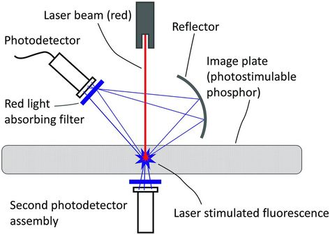
Figure 28.5 Illustration of the optically stimulated readout of a CR cassette, where a laser beam, typically operating at wavelengths corresponding to red, stimulates the cassette resulting in fluorescent emission of blue photons that are recorded by photodetectors.
In contrast to the CR approach, a newer generation of x-ray image sensors uses a scintillator plate with a thickness of about 300–700 microns as the primary detector of x-rays and an electronic amorphous silicon image sensor (flat-panel detector) that is in contact with the scintillator (38–43). This technology is generally referred to as “DR,” for digital radiography, and is illustrated in Fig. 28.6. In this approach, the x-rays interact with the scintillator causing it to emit light (scintillations). These scintillations are promptly detected by the flat-panel detector which consists of a rectangular array of a few million individual detectors (pixels) which record the location and the intensity of the x-ray induced scintillations. Therefore, the image is recorded by the pixelated amorphous silicon sensor with specific x and y coordinates and defining each point in the image plane, as well as an intensity value, typically from zero to 4095 (12 bits per pixel) providing 4096 intensity levels or levels of gray. In this process, x-rays are first converted to light, and the light is converted to electrons (electric current) by the silicon photodetector elements. The term “indirect conversion” is frequently used for this process because of the intermediate step of light creation due to x-ray interaction in the scintillator before converting the light to electric current. The smallest pixel size currently attainable with this technology is about 50 microns, but typically the pixel size is between about 140 and 200 microns.
Figure 28.6 Illustration of a wireless DR cassette using a scintillator for converting x-rays to light and an array of TFT coupled amorphous silicon photodiodes to convert light to electronic signal.
Another approach for DR uses a layer of amorphous selenium with thickness between 100 and 600 microns as the primary detector of x-rays (31, 44). Instead of producing light, selenium generates a very small electric current in response to the x-ray interaction. In this process, x-rays are converted directly to electrons (electric current) without the intermediate step of scintillation light and, hence, is referred to as direct conversion. This electric current is subsequently detected by the amorphous silicon array resulting in the same type of electronic image as with amorphous silicon detectors. This approach has proved to be very successful for digital mammography but it has yet to be optimized for radiography. Its main advantage is in its high spatial resolution, but the use of a thick selenium layer for absorption of the high energies in general radiography currently presents some technical challenges.
Selecting the best DR detector
There is no simple answer as to the best detector for DR, and such selection is especially challenging for imaging suspected child abuse. A recent study provided insight on the relative merits of DR technologies (45). Skeletal surveys require high spatial resolution and high contrast at the lowest possible radiation dose. CR systems are convenient because of their cassette format, small form-factor, and wide availability. However, a CR system used for general adult radiography is not ideally suited for the high-resolution requirements of skeletal pediatric surveys. Caution is advised to carefully evaluate the suitability of a given CR system for the intended task, particularly in terms of the resolution requirements for pediatric SSs. While nominally “high-resolution” CR systems are available from various vendors, their performance may vary. If properly used, high-resolution CR can offer adequate image quality for SSs and in general for radiographic applications requiring high resolution. In general, high-resolution CR systems are not the most radiation dose efficient. This is in part due to the inherent inefficiencies in the laser-induced optical readout approach. These systems continue to evolve and a properly configured and well-maintained CR system can be used for such studies.
Flat-panel DR systems offer dose efficiency due to their excellent stopping power for x-rays (typically better than 80% or higher) and excellent image noise characteristics (45). This performance is due to the close proximity of the scintillator to the amorphous silicon sensor that enables high capture efficiency for x-ray induced scintillations. DR is in principle superior to CR in terms of radiation dose efficiency, image noise levels, and contrast. However, in practice CR may be more conveniently available than high-resolution DR and, therefore, CR may be the only realistic option for many facilities. A DR detector is typically more bulky, heavier, and much more costly than a CR cassette. Optimized CR systems can deliver high image quality at an acceptable dose. For this reason, DR detectors have been used mostly as fixed detectors, either on the wall or under the radiographic table. Recent technical developments have enabled the manufacturing of DR cassettes, similar in form factor to CR cassettes, that are wireless and completely portable (Figure 28.6). This represents a tremendous technologic improvement, and high-resolution DR cassettes are being introduced. As these developments materialize it is likely that DR systems will be widely used for high-resolution pediatric skeletal imaging (46). In a recent study, improved imaging characteristics with one type of DR technology was demonstrated by using an “irradiation side sampling” approach, essentially by irradiating the detector from the back side (47). This approach was described previously for high-resolution mammographic imaging (48).
The impact of DR technology in radiographic imaging cannot be overemphasized. Its development represents a major milestone in the evolution of x-ray imaging technology. These detectors are currently used not only for static x-ray images but also for dynamic fluoroscopic examinations. Used either in the static or fluoroscopic mode, these detectors deliver high and consistent image quality with the ability for digital storage and communication of images. The technical challenges to construct such large detectors consisting of more than 5 million pixels with size in the order of 100 microns have been daunting but they are now a reality. Current technologic efforts are directed towards the development of x-ray detectors with higher spatial resolution and with increased capture efficiency for x-rays. Currently, the best detectors capture about 70–80% of the available x-rays, and improved detectors are needed for attaining close to 100% capture efficiency. Greater x-ray capture efficiency can be achieved by increasing the thickness of the primary detector, currently a layer of thallium-doped cesium iodide scintillator with a thickness between about 200 and 700 microns. However, increasing this thickness is known to degrade the spatial resolution that can blur fine anatomic detail in DR. There is a continuing need to develop new x-ray detectors that exhibit increased efficiency without degradation in spatial resolution. Research efforts are now directed towards the new generation of x-ray detectors that will have higher x-ray detection efficiency and will count individual x-ray photons. Success in this endeavor will contribute to improved image quality at a reduced radiation dose to the patient.
Fluoroscopy
In x-ray fluoroscopy, similar to radiography, the x-ray beam passing through a part of the body is detected by an integral assembly of scintillator and a photosensitive device which can be a camera-coupled image intensifier (an older technology) or in newer systems, a flat-panel detector that is a DR detector modified for fast image data readout. Upon detection of x-rays, the detector signal is directed to a digital image display for real-time direct viewing. Images can be viewed continuously and digitally stored.
Fluoroscopy enables observation of voluntary or involuntary motion of parts of the body or organs and is used in numerous procedures, including upper and lower gastrointestinal studies and angiography. Modern fluoroscopic techniques use pulse mode x-ray acquisition for reducing motion-induced blurring. The default acquisition mode in fluoroscopy is 30 images per second commonly called frames per second or fps. In recent years it has been found that 30 fps is useful only when very fast dynamic imaging is needed. In most fluoroscopic imaging a much slower frame rate is sufficient for diagnosis. Therefore, 15 fps and 7.5 fps or even slower frame rates are now commonly used. Slower frame rates enable radiation dose reduction because fewer x-ray exposures are taken during a fluoroscopic procedure. Flat-panel digital x-ray detectors are gradually replacing image intensifiers. The new detectors generate geometric distortion-free images, better spatial uniformity of the signal, and improved image contrast over the entire field of view.
Digital fluoroscopy is used effectively in digital subtraction angiography (DSA), in which two digitized images are produced, one before intravascular contrast agent and another after the injection. The computer then subtracts one image from the other, and the resultant image displays only the structures (opacified vessels) with the contrast agent. Fluoroscopic techniques provide a very powerful tool in pediatric imaging, but they can overexpose the patient to radiation if not used properly. Fluoroscopy has the potential of imparting a high radiation dose; therefore, measures must be taken to minimize the dose to children from these procedures. Fluoroscopic systems must be adjusted properly for pediatric applications and this requires particular attention to the technical details (49, 50). It must not be assumed that fluoroscopy systems that were calibrated for adult imaging are optimized with respect to dose and image quality for pediatric imaging. Physicians practicing fluoroscopy, especially pediatric procedures, must be appropriately trained on the radiation dose aspects of fluoroscopy (51).
One challenge with general purpose fluoroscopic systems is in their less than ideal spatial resolution and dose efficiency required for some pediatric imaging tasks, especially for certain interventional procedures in infants. Research in high-resolution fluoroscopy has been in progress in recent years (52–54) and it is likely that high-resolution flat-panel fluoroscopic detectors (pixel smaller than 140 microns) will become available in the near future.
Computed tomography
The introduction of computed axial tomography (CAT) scans in the mid 1970s represents a major milestone in radiology since the invention of x-rays. Allan Cormack, a physicist, and Godfrey Hounsfield, an engineer, were awarded the Nobel Prize in Medicine in 1979 for their work that led to the development of this technology. CT images are cross-sectional slices. Conventionally, CAT scanners displayed axial slices through the body along the vertical axis from the feet up towards the head. In modern CT, the images are not limited to axial slices; coronal and sagittal reformations can be displayed in conjunction with appropriate acquisition and reconstruction techniques, and the anatomy can be depicted in three dimensions with advanced visualization techniques. Therefore, the term axial did not accurately reflect the capabilities of CT, and instead of CAT, the term CT is now used by radiology professionals. The introduction of CT enabled physicians for the first time to visualize internal structures without substantial interference from surrounding tissues.
During image acquisition, a fan-shaped x-ray beam is directed from the x-ray tube through the patient and is shown in Figure 28.7. The transmitted radiation is intercepted by an array of detectors that map the relative x-ray attenuation of tissues along the x-ray beam path. The x-ray tube and the detector array are rotated in unison around the body and after acquiring about 900 x-ray projections in a 360-degree rotation a mathematical reconstruction algorithm is used to generate the tomographic image of the scanned body volume. The tomographic reconstruction depicts the anatomy by dividing it into volume elements (voxels) as small as 0.5 mm on each side. Typically, a single CT slice of selected thickness consists of a matrix of 512 × 512 picture elements (pixels), each displaying a shade of gray that is represented by a number ranging from –1000 to +4000 called a Hounsfield Unit (HU), or more commonly, the CT number. The CT number represents the relative attenuation of the anatomy with respect to water, which by definition is assigned a CT number of zero. Fat has a CT number between –20 and –70, air has a value of –1000 and blood and muscle have a CT number of about +40. Various soft tissues have CT numbers typically in the range from +20 to +70, and compact bone has a CT number greater than +200. The high contrast sensitivity of CT allows detection of contrast differences as small as 0.25% or approximately a difference in attenuation between different tissues of about 0.2%. This contrast discrimination is about one order of magnitude better than with DR. Contrast differences between tissues that are lower than about 3% cannot be detected by DR. CT excels in the discrimination of very subtle contrast variations between different tissues and between different physical or pathologic states within the same type of tissue. The use of contrast media further enhances the ability to differentiate among tissues that do not provide adequate native attenuation difference. For this reason, oral or IV contrast materials are used commonly.
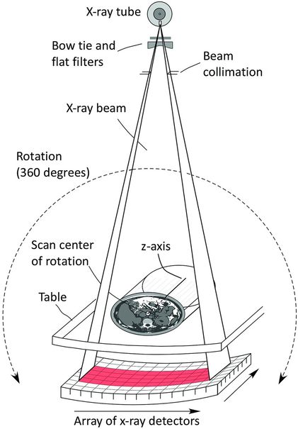
Figure 28.7 In CT acquisition a fan beam of x-rays is directed from the x-ray tube towards the detector. The x-ray tube and detector are rotated in unison around the scan center of rotation, which is aligned with the patient. Approximately 900 projections or more are acquired during the gantry rotation and mathematically reconstructed to provide cross-sectional images of the patient.
Related posts:
Stay updated, free articles. Join our Telegram channel

Full access? Get Clinical Tree


