RADIOGRAPHIC EQUIPMENT
The basic components of a radiography unit are a source of radiation (x-ray tube) and a receiving medium (x-ray film in the case of conventional plain film radiography). Figures 3-1 and 3-2 identify a stool, table, shields, side markers, and other accessories that are used for the radiographic setup.
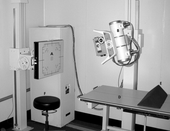 |
| FIG. 3-1 Typical radiographic system and related equipment, including: A, grid cabinet (Bucky); B, x-ray tube; C, collimator; D, movable table; E, positioning sponge; and F, stool. |
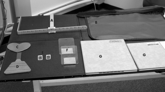 |
| FIG. 3-2 Tools and accessories used for radiographic examinations, including: A, measuring calipers; B, lead apron; C, female gonad shield; D, male gonad shield; E, right and left side (Mitchell) markers; F, filters; and G, cassettes. |
RADIOGRAPHIC TECHNIQUE
The radiographic techniques listed in this chart were derived using the following parameters:
• 300/125 kVp single phase generator*
*For high-frequency systems, lower the listed kV by 5 and decrease the mAs by half.
• 400-speed rare earth screens with matched film or
• Extremity detail screens with matched films†
†100-Speed cassettes can be substituted for extremity detail screens. The same film used in 400-speed cassettes can be used in 100-speed cassettes as long as spectral matching remains the same.
• 10:1 stationary grids
• Automatic processor
The suggested technique is within a fixed kilovolt (kV) range per body part. In smaller patients the lower spectrum of the kV range is used; in larger patients the upper range of kV is used. In this system the milliampere-seconds (mAs) is variable and corrections in exposure factors require changing the mAs only. To correct the exposure factors in a film that is underexposed, the mAs must be changed by a minimum of 30% to note a detectable change or by 100% for a significant change. The reverse is true for films that are overexposed. When a fixed kV system is used, only one exposure factor, the mAs, needs to be changed to correct for errors. The techniques contained in the chart provide a starting point of adequate exposures for a radiographic system similar to the one listed in the preceding. Corrections for individual variations in machines are made by adjusting the mAs only because the chart was formulated using the fixed kV technique.
There may be instances when a change in penetration, or kVp, is necessary. When a film is critiqued, if the bony detail is too light so as to appear nonexistent, a 15% increase in kVp provides the necessary penetration. An increase in mAs is required if the bony detail is present but the overall appearance of the film is too light.
PATIENT PREPARATION
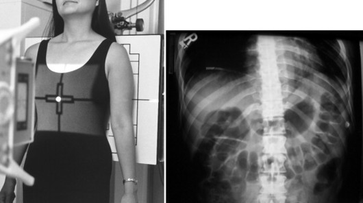
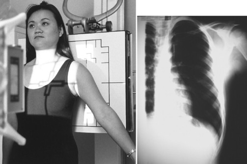
Good patient education is essential and must include a thorough explanation of the study being performed and the patient’s role during the examination. Protection methods and breathing instructions should be reviewed. Patients should be properly gowned and all artifacts should be removed before the radiographic examination begins (Fig. 3-3). Female patients of childbearing years should be assessed for possible pregnancy. If there is a possibility of pregnancy, the examination should be delayed, if possible, until it can be determined the patient is not pregnant, either by a negative human chorionic gonadotropin test or the start of menses. If possible, all radiographic examinations of the lumbar spine, abdomen, and pelvis should be scheduled during the first 10 days following the onset of menstruation because this is the least likely time for pregnancy to occur. Appropriate gonadal shielding should be used in both male and female patients whenever possible.
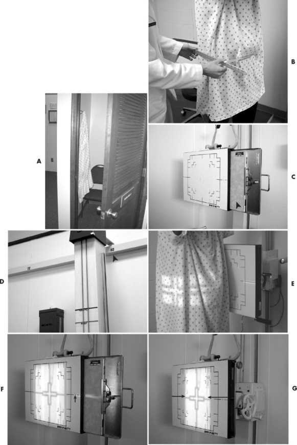 |
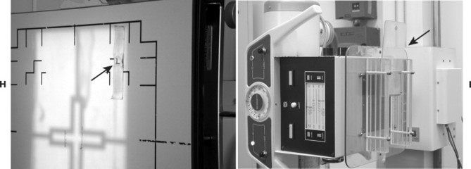 |
| FIG. 3-3 The radiographic setup is done most proficiently by following a general sequence. The sequence begins with patient preparation, including, A, gowning; followed by, B, measurement technique selection; C, film selection and placement; D, choice of focal film distance; E, central ray placement; F, alignment of the center of the film and the central ray; G, collimation to film size. H, side marker placement; and sometimes, I, use of filter. |
USING THE CHARTS
The following tables present commonly performed radiographic projections. The routine study is highlighted in blue. A routine study is the minimum number of views that must be performed to obtain a complete study of the area. Additional views are included in most sections and can be added to the basic study. Additional views are added to better demonstrate an area in question or to assess motion or stability. As reference, radiographic views are named by the body part being examined and either the direction the x-ray beam is passing through the body (anteroposterior, [AP]) or the portion of the body part touching the grid for oblique angles of the body (right posterior oblique [RPO]) (Fig. 3-4).
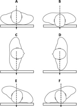 |
| FIG. 3-4 Radiographic views. The term radiographic “projection” references the path of the central ray as it exits the x-ray tube and passes through the patient’s body. For example, A denotes an anteroposterior (AP) projection and B a posteroanterior (PA) projection. In the extremities, lateral projections are similarly described by the direction of the central ray; hence, mediolateral and lateromedial projections are possible. However, when one deals with the head, neck, or body tunk, the lateral and oblique projections are further clarified by the specific “position” of the patient. Position denotes the placement of the patient’s body, specifically the portion of the patient’s anatomy that is in contact with the Bucky. For example, C indicates a lateral projection in a right lateral position and D indicates a lateral projection in a left lateral position. In E, the patient is in a left anterior oblique (LAO) position, and in F the patients is in a right anterior oblique (RAO) position, both corresponding to posteroanterior oblique projections. |
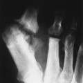
Each table explains the position setup, central ray placement, tube angulation, optimal film size, and focal film distance for each view. To conserve x-ray film and facilitate viewing, sometimes the film is divided so that multiple views of a body part are seen on a single film (Fig. 3-5). For each setup in the tables, there is a picture demonstrating the position and central ray placement and another to exhibit the anatomy demonstrated by the setup. The kV and mAs section lists the type of film screen combination used and whether the study is performed with the use of a grid or table top. If the use of a grid is listed, a fast film screen combination such as rare earth is suggested. If detailed or nongrid is listed, a slower speed film screen combination is suggested, such as those found in extremity cassettes or 100-speed cassettes. A suggested kV and mAs range is also provided for systems described in the previous section on technique. The “Additional Information” section describes other views that may be done to better demonstrate the desired anatomy. Technical tips are also included to aid in obtaining optimal studies.
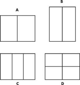 |
| FIG. 3-5 A through D, For some small body parts (e.g., foot and wrist), the x-ray film may be divided to accommodate several projections. |
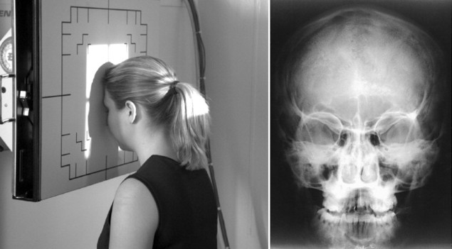
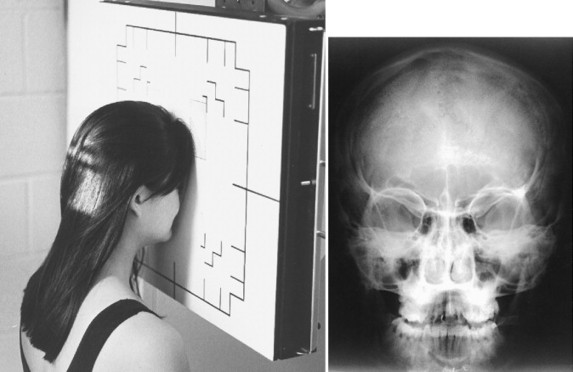
| Position: | PA Caldwell | |
|---|---|---|
| Patient Preparation: | Remove any artifacts in the desired field (e.g., earrings, dentures, hair appliances). | |
| Measurement: | Place caliper base at the back of the skull. Slide the caliper arm until it rests lightly at the nasion. | |
| Shielding: | Secure lead apron around patient. | |
| Film Selection: | 10 × 12 | |
| Film Placement: | Place vertical in Bucky. | |
| ID Placement: | ID should be in lower corner of collimation field. | |
| Patient Placement: | Place patient with nose and forehead against Bucky so that the orbitomeatal line is perpendicular to the film. | |
| Technique Selection: | kVp 70 to 80; mAs 20 to 40 | |
| SID: | 40″ | |
| Central Ray Placement: | Using a 15-degree caudal tube tilt, central ray enters the back of the skull so as to exit the nasion. | |
| Collimation: | To film size. | |
| Marker Placement: | Within the collimation field on either the right side or left side of patient’s head. | |
| Breathing Instructions: | Do not breathe. Do not move. | |
| Anatomy Visualized: | Frontal bone, frontal and ethmoid sinuses, greater and lesser wing of the sphenoid, superior orbital fissure, foramen rotundum, orbital margins. | |
| Additional Information: | The caudal tube angle may be increased to 30 degrees to optimally define the inferior orbital rim area. | |
| Petrous pyramids appear in the lower one third of the orbit as performed in the preceding. These are projected below the inferior orbital rim on the 30-degree angle. | ||
| ||
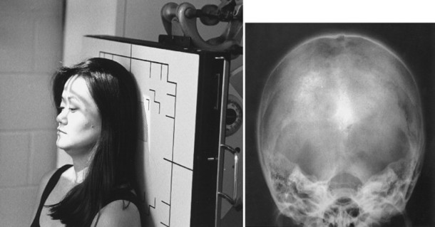
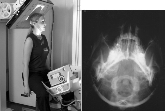
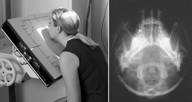
| Position: | AP Towne | |
| Patient Preparation: | Remove any artifacts in the desired field (e.g., earrings, dentures, hair appliances). | |
| Measurement: | Place base bar of caliper on occiput. Slide moveable bar in toward the patient’s head so as to touch the glabella. | |
| Shielding: | Secure lead apron around patient. | |
| Film Selection: | 10 × 12 | |
| Film Placement: | Place vertically in Bucky. | |
| ID Placement: | ID should be in lower corner of collimation field. | |
| Patient Placement: | Place patient in AP position so back of head touches Bucky. Tuck the chin so the orbitomeatal line is perpendicular to the film. | |
| Technique Selection: | kVp 70 to 80; mAs 30 to 60 | |
| SID: | 40″ | |
| Central Ray Placement: | Central ray is angled 30 degrees caudally and enters 2″ above the glabella (superciliary arch). | |
| Collimation: | To film size. | |
| Marker Placement: | Within the collimation field on either the right side or left side of patient’s head. | |
| Breathing Instructions: | Do not breathe. Do not move. | |
| Anatomy Visualized: | Occipital bone, petrous pyramids, foramen magnum with dorsum sellae and posterior clinoids projected through it. | |
| Additional Information: | If the patient cannot tuck the chin sufficiently, adjust the head tilt so that the infraorbitomeatal line is perpendicular to the film and increase the tube tilt to approximately 37 degrees. | |
| ||
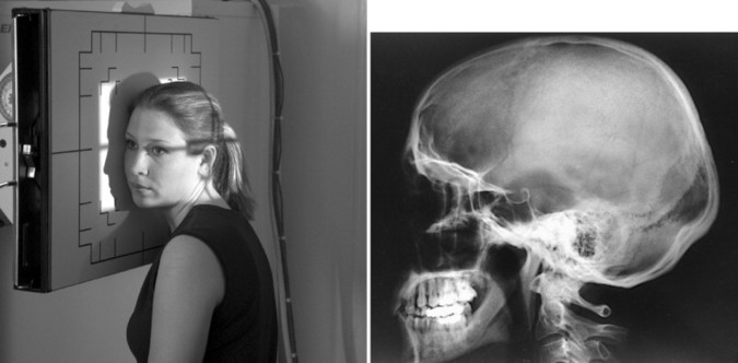
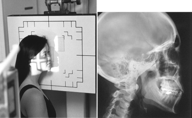
| Position: | Lateral Skull | |
| Patient Preparation: | Remove any artifacts in the desired field (e.g., earrings, dentures, hair appliances). | |
| Measurement: | Place the base bar of the calipers on the temporal bone of one side of the head and move the slider bar toward the patient’s head so as to touch the temporal bone on the other side of the head. | |
| Shielding: | Secure lead apron around patient. | |
| Film Selection: | 10 × 12 | |
| Film Placement: | Place horizontally in Bucky. | |
| ID Placement: | ID should be in lower corner of collimation field. | |
| Patient Placement: | Place patient with side of head against Bucky. Oblique the patient’s body for comfort. The interpupillary line is perpendicular to the film. The external occipital protuberance and the nasion should be equidistant from the film to prevent rotation. | |
| Technique Selection: | kVp 70 to 80; mAs 20 to 40 | |
| SID: | 40″ | |
| Central Ray Placement: | The central ray enters 1 superior and anterior to the external auditory meatus. | |
| Collimation: | To film size. | |
| Marker Placement: | Within the collimation field denoting which side of the patient’s head is touching the Bucky. | |
| Breathing Instructions: | Do not breathe. Do not move. | |
| Anatomy Visualized: | Lateral cranium closest to film, sella turcica, anterior and posterior clinoids, and ethmoid sinuses. AP, Anteroposterior; ID, identification; PA, posteroanterior; SID, source-to-image distance. | |
| ||
| Position: | PA Waters | |
|---|---|---|
| Patient Preparation: | Remove any artifacts in the desired field (e.g., earrings, dentures, hair appliances). | |
| Measurement: | Place base bar of calipers on back of skull and move slider bar toward patient’s face until it touches between bottom lip and tip of chin. | |
| Shielding: | Secure lead apron around patient. | |
| Film Selection: | 8 × 10 | |
| Film Placement: | Place vertically in Bucky so center of cassette is centered to the acanthion. | |
| ID Placement: | ID should be in lower corner of collimation field. | |
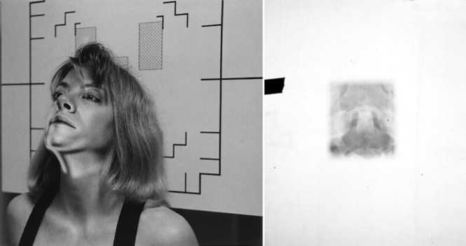
| Patient Placement: | Place patient in PA position with neck in slight extension so chin and nose rest against Bucky. The orbitomeatal line should form a 55-degree angle to the film. | |
| Technique Selection: | kVp 70 to 80; mAs 20 to 40 | |
| SID: | 40″ | |
| Central Ray Placement: | The central ray is directed perpendicular to the Bucky and is centered to the center of the cassette. | |
| Collimation: | To film size. | |
| Marker Placement: | Within the collimation field on either the right side or left side of patient’s head. | |
| Breathing Instructions: | Do not breathe. Do not move. | |
| Anatomy Visualized: | Floor of the orbits, maxillary sinuses. | |
| Additional Information: | Should be done in upright position to evaluate air fluid levels in the maxillary sinuses. Petrous ridges should be projected in the lower half of the maxillary sinuses below the inferior orbital rim. Good view for evaluation of possible “blowout” orbital fractures. | |
| ||
| Position: | PA Caldwell | |
| Patient Preparation: | Remove any artifacts in the desired field (e.g., earrings, dentures, hair appliances). | |
| Measurement: | Place base bar of calipers against back of head. Move slider bar toward patient’s face to rest on nasion. | |
| Shielding: | Secure lead apron around patient. | |
| Film Selection: | 8 × 10 | |
| Film Placement: | Place vertically in Bucky with center of cassette aligned to the nasion. | |
| ID Placement: | ID should be in lower corner of collimation field. | |
| Patient Placement: | Place patient in the PA position against the Bucky so that the nose and forehead are against the Bucky and the orbitomeatal line is perpendicular to the cassette. | |
| Technique Selection: | kVp 70 to 80; mAs 20 to 40 | |
| SID: | 40″ | |
| Central Ray Placement: | The central ray is angled 15 degrees caudally and is centered to cassette. | |
| Collimation: | To film size. | |
| Marker Placement: | Within the collimation field on either the right side or left side of patient’s head. | |
| Breathing Instructions: | Do not breathe. Do not move. | |
| Anatomy Visualized: | Orbital rim, maxillae, nasal septum, and zygomatic bones. | |
| Additional Information: | For better definition of the inferior orbital rim area, increase the tube angle to 30 degrees. | |
| Petrous pyramids should be projected in the lower one third of the orbit with a 15-degree tube tilt and below the inferior orbital rim on the 30-degree tube tilt. | ||
| ||
| Position: | Lateral Facial Bones | |
| Patient Preparation: | Remove any artifacts in the desired field (e.g., earrings, dentures, hair appliances). | |
| Measurement: | Place the base bar of the calipers against the zygomatic arch. Move the slider bar of the calipers toward the patient’s face so it rests on the opposite zygomatic arch. | |
| Shielding: | Secure lead apron around patient. | |
| Film Selection: | 8 × 10 | |
| Film Placement: | Place vertically in Bucky. | |
| ID Placement: | ID should be in lower corner of collimation field. | |
| Patient Placement: | Place the patient in an anterior oblique position. Place the patient’s head in a lateral position with the side of interest resting against the Bucky. | |
| Technique Selection: | kVp 70 to 80; mAs 10 to 20 | |
| SID: | 40″ | |
| Central Ray Placement: | The central ray enters ½ posterior to the outer canthus. | |
| Collimation: | To film size. | |
| Marker Placement: | Within the collimation field denoting the side of the head that is closest to the Bucky. | |
| Breathing Instructions: | Do not breathe. Do not move. | |
| Anatomy Visualized: | Ethmoid, frontal, sphenoid, and maxillary sinuses in the lateral projection. | |
| Additional Information: | This view should be performed with the patient in the upright position to evaluate air fluid levels in the sinuses. | |
| ID, Identification; PA, posteroanterior; RAO, right anterior oblique; SID, source-to-image distance. | ||
| ||
| Routine: AP Open Mouth, AP Lower Cervical, Lateral Cervical | ||
|---|---|---|
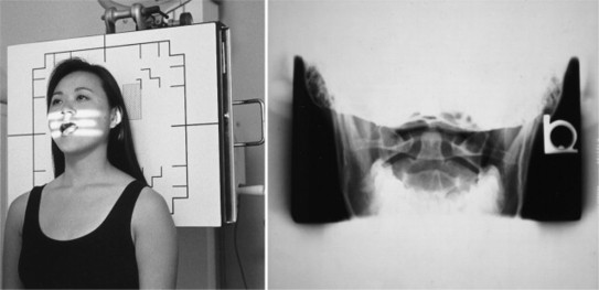
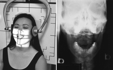
| Position: | AP Open Mouth | |
| Patient Preparation: | Remove any artifacts in the desired field (e.g., earrings, dentures, hair appliances). | |
| Measurement: | Place base bar of calipers on back of head. Instruct patient to open mouth. Move slider bar in toward patient’s face to corner of mouth (without touching patient’s mouth). | |
| Shielding: | Secure lead apron around patient. | |
| Film Selection: | 8 × 10 | |
| Film Placement: | Place vertically in Bucky. | |
| ID Placement: | ID should be in lower corner of collimation field. | |
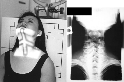
| Patient Placement: | Place patient in the AP position with back of shoulders resting against Bucky. The plane of the upper occlusal plate and occiput with mouth open should be parallel to the floor. | |
| Technique Selection: | kVp 70 to 80; mAs 10 to 15 | |
| SID: | 40″ | |
| Central Ray Placement: | The central ray enters the midpoint of the open mouth. | |
| Collimation: | Collimate just under the eyes vertically and to the mastoids horizontally. | |
| Marker Placement: | Within the collimation field on either the right side or left side of patient’s head. | |
| Breathing Instructions: | Do not breathe. Do not move. | |
| Anatomy Visualized: | Lateral masses, anterior and posterior arches of C1, odontoid process, pedicles, lamina, and spinous process of C2. | |
| Additional Information: | Correct head placement is essential. If teeth superimpose odontoid, tip head back. If occiput superimposes odontoid, tip head forward. In extreme cases, the oblique odontoid or Fuchs view may be used. | |
| ||
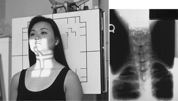
| Position: | AP Lower Cervical | |
| Patient Preparation: | Remove any artifacts in the desired field (e.g., earrings, dentures, hair appliances). | |
| Measurement: | Place the base bar of the calipers against the posterior aspect of the cervical spine at the level of C4. | |
| Move the slider bar toward the patient until it touches the anterior aspect of the cervical spine at C4. | ||
| Shielding: | Secure lead apron around patient. | |
| Film Selection: | 8 × 10 | |
| Film Placement: | Place vertically in Bucky. | |
| ID Placement: | ID should be in upper corner of collimation field. | |
| Patient Placement: | Place patient in the AP position with back of shoulders against the Bucky. | |
| Technique Selection: | kVp 65 to 75; mAs 6 to 12 | |
| SID: | 40″ | |
| Central Ray Placement: | The central ray should be angled 15 degrees cephalically so as to enter the area of C4 (thyroid cartilage). | |
| Collimation: | To film size vertically. To mastoids horizontally. | |
| Marker Placement: | Within the collimation field on either the right side or left side of patient’s head. | |
| Breathing Instructions: | Do not breathe. Do not move. | |
| Anatomy Visualized: | Pedicles, lamina, transverse processes, vertebral bodies, and uncinate processes of C3 to C7. Lung apices are also visualized. | |
| Additional Information: | If mandible obscures C3 and C4, elevate chin slightly or increase the angulation on the tube. | |
| If a lesion is suspected in visualized lung apices, a PA and lateral chest radiograph should be performed. | ||
| ||
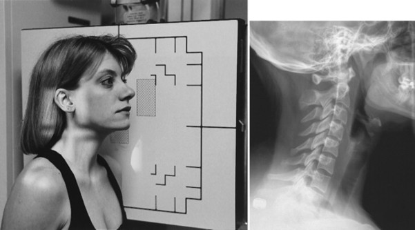
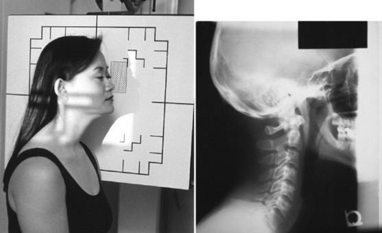
| Position: | Lateral Cervical (Neutral Position) | |
| Patient Preparation: | Remove any artifacts in the desired field (e.g., earrings, dentures, hair appliances). | |
| Measurement: | Place base bar of calipers on lateral side of patient’s neck at C4 level. Move slider bar of calipers toward patient’s neck so as to rest at the C4 level. | |
| Shielding: | Secure lead apron around patient. | |
| Film Selection: | 8 × 10 | |
| Film Placement: | Place vertically in Bucky. | |
| ID Placement: | ID should be in upper corner of collimation field. | |
| Patient Placement: | Place patient (standing or seated) next to the Bucky in the lateral position. | |
| Technique Selection: | kVp 70 to 80; mAs 15 to 30 | |
| SID: | 72 | |
| Central Ray Placement: | The central ray is directed horizontally to the C4-5 disc level. | |
| Collimation: | To film size. | |
| Marker Placement: | Within the collimation field on the side of the patient that is closest to the film. | |
| Breathing Instructions: | Full exhalation, to drop shoulders. | |
| Anatomy Visualized: | Vertebral bodies, intervertebral disc spaces, articular pillars, spinous processes, and anterior and posterior arch of atlas. | |
| Additional Information: | This the most important view for the evaluation of cervical spine trauma. This film should be evaluated before continuing with the remainder of the cervical series in trauma cases. If C7 is poorly visualized, a swimmer’s view may be used. | |
| ||
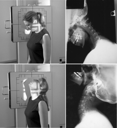
| Position: | Lateral Cervical (Flexion and Extension: for Trauma) | |
| Patient Preparation: | Remove any artifacts in the desired field (e.g., earrings, dentures, hair appliances). | |
| Measurement: | Same as Lateral Cervical (Neutral position). | |
| Shielding: | Secure lead apron around patient. | |
| Film Selection: | 10 × 12 | |
| Film Placement: | Place vertically in Bucky. | |
| ID Placement: | ID should be in upper corner of collimation field. | |
| Patient Placement: | Same as Lateral Cervical (Neutral position). For Flexion view, ask patient to tuck chin into chest and roll head down so eyes rest on chest. For Extension, ask patient to roll head backward, looking toward the ceiling. | |
| Technique Selection: | kVp 70 to 80; mAs 15 to 30 | |
| SID: | 72 | |
| Central Ray Placement: | Same as Lateral Cervical (Neutral position). | |
| Collimation: | To film size. | |
| Marker Placement: | Within the collimation field marking the side of the cervical spine that is closest to the film. | |
| Breathing Instructions: | Full exhalation. | |
| Anatomy Visualized: | These are additional views performed to demonstrate and evaluate excessive or diminished intersegmental mobility of the cervical spine. | |
| Additional Information: | Flexion and Extension views should be performed only after the Lateral Cervical (Neutral position) view has been evaluated for a gross instability. | |
| ||
| Position: | Cervical Oblique (for Trauma) | |
| Patient Preparation: | Remove any artifacts in the desired field (e.g., earrings, dentures, hair appliances). | |
| Measurement: | Same as Lateral Cervical. | |
| Shielding: | Secure lead apron around patient. | |
| Film Selection: | 8 × 10 | |
| Film Placement: | Place vertically in Bucky. | |
| ID Placement: | ID should be in upper corner of collimation field. | |
| Patient Placement: | The right and left oblique projections may be done in an anterior or posterior position. For anterior obliques (RAO and LAO), the anterior aspect of the patient’s shoulder is placed against the Bucky and the body is angled 45 degrees with the grid. For posterior obliques (RPO and LPO), the posterior aspect of the patient’s shoulder is placed against the Bucky and the body is angled 45 degrees with the grid. The anterior oblique position relates less radiation dose to the thyroid gland and better accommodates the diverging x-ray beam with the cervical lordosis. | |
| Technique Selection: | kVp 70 to 80; mAs 15 to 30 | |
| SID: | 72 | |
| Central Ray Placement: | Angle tube 15 degrees cephalically for posterior obliques or 15 degrees caudally for anterior obliques at the level of C4. | |
| Collimation: | To film size. | |
| Marker Placement: | Within the collimation field on the side of the patient that is closest to the Bucky. | |
| Breathing Instructions: | Full exhalation. | |
| Anatomy Visualized: | Borders of the intervertebral foramen, pedicles, facet joints, uncinates and posterior vertebral bodies. | |
| Additional Information: | Optimal view for visualization of bony foraminal effacement resulting from cervical spine spondylosis. | |
| Optimal view for evaluation of pedicles for possible fracture and relationship of superior and inferior facet joints for possible dislocation in trauma cases. The posterior cervical oblique positions (RPO and LPO) demonstrate the opposite side intervertebral foramen (e.g., RPO shows left foramen) and the anterior cervical oblique positions (RAO and LAO) demonstrate the same side intervertebral foramen (e.g., RAO shows right foramen). The anterior oblique position relates less radiation dose to the thyroid and the divergence of the x-ray beam better approximates the intervertebral disc angles, and therefore anterior obliques are typically preferred. | ||
| ||
| Position: | Oblique Odontoid (Kasabach method) | |
| Patient Preparation: | Remove any artifacts in the desired field (e.g., earrings, dentures, hair appliances). | |
| Measurement: | Use recommended technique. | |
| Shielding: | Secure lead apron around patient. | |
| Film Selection: | 8 × 10 | |
| Film Placement: | Place vertically in Bucky. | |
| ID Placement: | ID should be in upper corner of collimation field. | |
| Patient Placement: | AP with 45-degree rotation of the head. | |
| Technique Selection: | kVp 75 to 85; mAs 15 to 25 | |
| SID: | 40″ | |
| Central Ray Placement: | Central ray is angled 15 degrees caudally to enter midway between the outer canthus and the external auditory meatus. | |
| Collimation: | To film size. | |
| Marker Placement: | Within the collimation field on the side of the head that is touching the Bucky. | |
| Breathing Instructions: | Do not breathe. Do not move. | |
| Anatomy Visualized: | Demonstrates oblique view of odontoid process. | |
| Additional Information: | This study is performed when the odontoid cannot be visualized on an AP open mouth view. In cases of trauma or in patients with decreased range of motion, the entire body can be rotated 45 degrees. | |
| ||
| Position: | Fuchs (Nontrauma) | |
| Patient Preparation: | Remove any artifacts in the desired field (e.g., earrings, dentures, hair appliances). | |
| Measurement: | Using the calipers, place the base bar under the chin. Move the slider bar so that it touches the patient at the vertex of the skull. | |
| Shielding: | Secure lead apron around patient. | |
| Film Selection: | 8 × 10 | |
| Film Placement: | Place vertically in Bucky. | |
| ID Placement: | ID can be either up or down because of collimation. | |
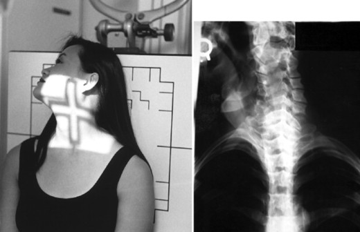
| Patient Placement: | Patient is in the AP position with the neck extended so that the vertex of the skull touches the center of the Bucky. | |
| Technique Selection: | kVp 70 to 80; mAs 10 to 15 | |
| SID: | 40″ | |
| Central Ray Placement: | Central ray is angled 0-15 degrees (depending on the extent to which the patient can extend his or her neck) and enters 1″ below the chin. | |
| Collimation: | To part size, approximately 5″ × 5″ | |
| Marker Placement: | Within the collimation field on either the right side or left side of patient’s head. | |
| Breathing Instructions: | Do not breathe. Do not move. | |
| Anatomy Visualized: | AP projection of the odontoid process as it lies within the shadow of the foramen magnum. | |
| Additional Information: | This view should not be performed on a trauma patient or a patient with limited range of motion. Use of linear tomography may be required to better visualize the odontoid in cases of suspected fractures. This is a supplemental view used when the dens cannot be visualized on the AP open mouth view. | |
| ||
| Position: | Pillar | |
| Patient Preparation: | Remove any artifacts in the desired field (e.g., earrings, dentures, hair appliances). | |
| Measurement: | Same as AP Lower Cervical. | |
| Shielding: | Secure lead apron around patient. | |
| Film Selection: | 8 × 10 | |
| Film Placement: | Place vertically in Bucky. | |
| ID Placement: | ID should be in upper corner of collimation field. | |
| Patient Placement: | Patient is in AP position with neck in full extension. | |
| Technique Selection: | kVp 70 to 80; mAs 10 to 15 | |
| SID: | 40″ | |
| Central Ray Placement: | Central ray is angled 35 degrees caudally and enters midline of the cervical spine, exiting at the C7 spinous process. | |
| Collimation: | To film size. | |
| Marker Placement: | Within the collimation field on either the right side or left side of patient’s head. | |
| Breathing Instructions: | Do not breathe. Do not move. | |
| Anatomy Visualized: | Shape and height of the pillar. | |
| Additional Information: | Computed tomography (CT) is the examination of choice to demonstrate pillar fractures, making this a view rarely performed. | |
| ||
| Position: | Vertebral Arch (AP Caudal Tilt) | |
| Patient Preparation: | Remove any artifacts in the desired field (e.g., earrings, dentures, hair appliances). | |
| Measurement: | Same as AP Lower Cervical. | |
| Shielding: | Secure lead apron around patient. | |
| Film Selection: | 8 × 10 | |
| Film Placement: | Place vertically in Bucky. | |
| ID Placement: | ID should be in upper corner of collimation field. | |
| Patient Placement: | Patient is in AP position with neck in full extension, head obliqued. Both obliques are performed for comparison. | |
| Technique Selection: | kVp 70 to 80; mAs 10 to 15 | |
| SID: | 40″ | |
| Central Ray Placement: | Central ray is angled 25 degrees caudally and enters midthyroid cartilage approximately 3 below the external auditory meatus, exiting at the C7 spinous process. | |
| Collimation: | To film size. | |
| Marker Placement: | Within the collimation field denoting the side of the partient’s head closest to the film. | |
| Breathing Instructions: | Do not breathe. Do not move. | |
| Anatomy Visualized: | Shape and continuity of the posterior arch of the vertebrae. | |
| Additional Information: | Computed tomography (CT) is the examination of choice to demonstrate pillar fractures, making this a view rarely performed. | |
| ||
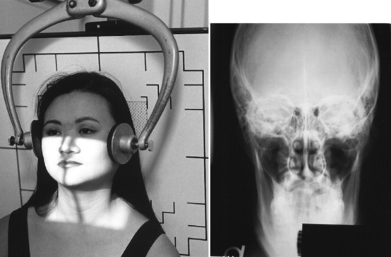
| Position: | Nasium* | |
| Patient Preparation: | Remove any artifacts in the desired field (e.g., earrings, dentures, hair appliances). | |
| Measurement: | Using calipers, place base bar at the level of the occiput. Move the slider bar toward the patient’s face until it rests on the glabella. | |
| Shielding: | Secure lead apron around patient. | |
| Film Selection: | 8 × 10 | |
| Film Placement: | Place vertically in Bucky. | |
| ID Placement: | ID should be in lower corner of collimation field. | |
| Patient Placement: | Patient is seated in the AP position. Bucky is tilted so as to touch the patient’s head and shoulders. | |
| Technique Selection: | kVp 70 to 80; mAs 15 to 30 | |
| SID: | 40″ | |
| Central Ray Placement: | Central ray is angled caudally so as to enter the glabella and exit the inferior tip of the mastoid process. | |
| The amount of angulation is determined by measurement obtained from the lateral cervical radiograph. | ||
| Collimation: | To film size. | |
| Marker Placement: | Within the collimation field on either the right side or left side of patient’s head. | |
| Breathing Instructions: | Do not breathe. Do not move. | |
| Anatomy Visualized: | Ocular orbits, lateral masses of C1, occipital condyles. | |
| Additional Information: | Filtration is used to cover the eyes. Head clamps are used to ensure head is held in a neutral position. This view demonstrates atlas laterality. | |
| ||
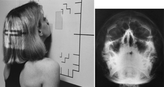
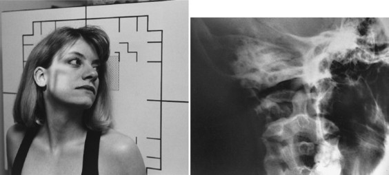
| Position: | Base Posterior* | |
| Patient Preparation: | Remove any artifacts in the desired field (e.g., earrings, dentures, hair appliances). | |
| Measurement: | Using the calipers, place the base bar at the vertex of the skull. Move the slider bar toward the patient resting the bar 1 below the chin. | |
| Shielding: | Secure lead apron around patient. | |
| Film Selection: | 8 × 10 | |
| Film Placement: | Place vertically in Bucky. The Bucky is tilted 45 degrees with the top of the Bucky toward the tube. | |
| ID Placement: | ID should be in lower corner of collimation field. | |
| Patient Placement: | Patient is seated in the AP position with head in neutral position. The vertex of the skull is placed in the center of the Bucky. | |
| Technique Selection: | kVp 75 to 85; mAs 20 to 30 | |
| SID: | 40″ | |
| Central Ray Placement: | Central ray is angled cephalically entering 1″ below the chin, passing ½ ″ anterior to the external auditory meatus, and exiting the vertex of the skull. | |
| Collimation: | To film size. | |
| Marker Placement: | Within the collimation field on either the right side or left side of patient’s head. | |
| Breathing Instructions: | Do not breathe. Do not move. | |
| Anatomy Visualized: | Atlas, axis, and nasal septum. | |
| Additional Information: | Filter out the eyes. Head clamps may be used to hold head in neutral position. This view is used to demonstrate atlas rotation. The vertex may be used as an alternate view. | |
| ||
| Position: | Palmer Open Mouth* | |
| Patient Preparation: | Remove any artifacts in the desired field (e.g., earrings, dentures, hair appliances). | |
| Measurement: | Using calipers, place the base bar against the occiput. Move the slider bar toward the patient’s open mouth, stopping 1 cm short of touching the face. | |
| Shielding: | Secure lead apron around patient. | |
| Film Selection: | 8 × 10 | |
| Film Placement: | Place vertically in Bucky. Bucky should be tilted to touch the back of the patient’s head and shoulders. | |
| ID Placement: | ID should be in upper corner of collimation field. | |
| Patient Placement: | Patient is seated in AP position with mouth open. | |
| Technique Selection: | kVp 70 to 80; mAs 10 to 15 | |
| SID: | 40″ | |
| Central Ray Placement: | The central ray is angled to stimulate the direction of the line between the upper occlusal plate and the base of the occiput (0-5 degrees) and enters the corners of the mouth. | |
| Collimation: | To film size. | |
| Marker Placement: | Within the collimation field on either the right side or left side of patient’s head. | |
| Breathing Instructions: | Do not breathe. Do not move. | |
| Anatomy Visualized: | Lateral masses, anterior and posterior arches of C1, odontoid process, pedicles, lamina and spinous process of C2, ocular orbits. | |
| Additional Information: | Use filter to cover the ocular orbits. Head clamps may be used to hold head in neutral position. This view demonstrates axis listing. | |
| ||
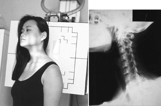
| Position: | Palmer Lateral* | |
| Patient Preparation: | Remove any artifacts in the desired field (e.g., earrings, dentures, hair appliances). | |
| Measurement: | Using calipers, place base bar against one side of patient’s neck. Move slider bar to rest comfortably on opposite side of neck. | |
| Shielding: | Secure lead apron around patient. | |
| Film Selection: | 10 × 12 | |
| Film Placement: | Place vertically in Bucky. | |
| ID Placement: | ID should be in upper corner of collimation field. | |
| Patient Placement: | Patient is seated in a true lateral position with head in neutral position. | |
| Technique Selection: | kVp 70 to 80; mAs 15 to 30 | |
| SID: | 72″ | |
| Central Ray Placement: | Central ray is angled 90 degrees, perpendicular to film entering transverse process of C1. | |
| Collimation: | To film size vertically. Horizontally, collimate to just behind the orbits. | |
| Marker Placement: | Within the collimation field on the side of the body closest to the film. | |
| Breathing Instructions: | Suspend respiration on exhalation to lower shoulders. | |
| Anatomy Visualized: | Vertebral bodies, intervertebral disc spaces, articular pillars, spinous processes, and anterior and posterior arch of the atlas. | |
| Additional Information: | This view demonstrates atlas superiority or inferiority. The measurements are also taken off of this view to determine the tube tilt for the nasium view. | |
| ||
| Position: | Vertex* | |
| Patient Preparation: | Remove any artifacts in the desired field (e.g., earrings, dentures, hair appliances). | |
| Measurement: | Same as Base Posterior. * | |
| Shielding: | Secure lead apron around patient. | |
| Film Selection: | 8 × 10 | |
| Film Placement: | Place vertically in Bucky. The Bucky is tilted 45 degrees so the bottom of the Bucky is closest to the tube. | |
| ID Placement: | ID should be in upper corner of collimation field. | |
| Patient Placement: | Patient is seated facing the Bucky. With neck extended, the chin should rest in the center of the Bucky. | |
| Technique Selection: | kVp 75 to 85; mAs 20 to 30 | |
| SID: | 40″ | |
| Central Ray Placement: | The central ray enters the vertex of the skull, passes ½ ″ of the external auditory meatus, and exits 1″ below the chin. | |
| Collimation: | To film size. | |
| Marker Placement: | Within the collimation field on either the right side or left side of patient’s head. | |
| Breathing Instructions: | Do not breathe. Do not move. | |
| Anatomy Visualized: | Atlas, axis, nasal septum. | |
| Additional Information: | Filtration is used over the ocular orbits. Head clamps may be used to hold the head in a neutral position. This view demonstrates atlas rotation. It is used as an alternate to the base posterior view. | |
| ||
| AP, Anteroposterior; ID, identification; LAO, left anterior oblique; LPO, left posterior oblique; PA, posteroanterior; RAO, right anterior oblique; RPO, right posterior oblique; SID, source-to-image distance. | ||
| *Special view used for Palmer Upper Cervical technique analysis. | ||
| Routine Thoracic Spine: AP and Lateral | ||
|---|---|---|
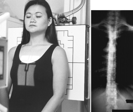
| Position: | AP Thoracic Spine | |
| Patient Preparation: | Remove any artifacts in the desired field (e.g., clothing with hooks, snaps, zippers). Place patient in gown. | |
| Measurement: | Using the calipers, place the base bar on the patient’s spine. Rotate the caliper so that it is over the patient’s shoulder. Then move the slider bar into the sternum of the patient. | |
| Shielding: | Secure lead apron around patient. | |
| Film Selection: | 7 × 17 or 14 × 17 | |
| Film Placement: | Place vertically in Bucky. The top of the cassette should be 1 to 1½ above the vertebral prominence. | |
| ID Placement: | ID should be in lower corner of collimation field. | |
| Patient Placement: | The patient is standing in the AP position with back against the Bucky. | |
| Technique Selection: | kVp 70 to 80; mAs 20 to 40 | |
| SID: | 40″ | |
| Central Ray Placement: | Center to the center of the cassette, approximately 3″ to 4″ below the sternal notch. | |
| Collimation: | To 7 × 17. | |
| Marker Placement: | Within the collimation field on either the right side or left side of patient’s spine. | |
| Breathing Instructions: | Suspend on inspiration. | |
| Anatomy Visualized: | Vertebral bodies, intervertebral disc spaces, pedicles, spinous and transverse processes, posterior ribs, and costovertebral joints. Paraspinal lines (pleural interface) can also be seen. | |
| Additional Information: | For best results, the tube should be positioned so the anode is toward the patient’s head and the cathode is down, taking advantage of the “heel effect.” | |
| Wedge filtration should be used to achieve a more uniform density. The filter should be placed down to the midsternum. | ||
| ||
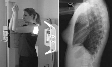
| Position: | Lateral Thoracic Spine | |
| Patient Preparation: | Remove any artifacts in the desired field (e.g., clothing with hooks, snaps, zippers). Place patient in gown. | |
| Measurement: | Standing behind the patient, place base bar of calipers under left arm. Move slider bar so as to snugly rest under right arm. | |
| Shielding: | Secure lead apron around patient. | |
| Film Selection: | 14 × 17 | |
| Film Placement: | Place vertically in Bucky. The top of the cassette should be 1½ above the vertebral prominence. | |
| ID Placement: | ID should be in upper corner of collimation field. | |
| Patient Placement: | Patient is in lateral position (depending on direction of spinal curve) with arms raised and elbows flexed. Humeri should be parallel to floor. | |
| Technique Selection: | kVp 75 to 85; mAs 40 to 60 | |
| SID: | 40″ | |
| Central Ray Placement: | Central ray to center of previously placed cassette. | |
| Collimation: | To film size vertically. To patient size horizontally. | |
| Marker Placement: | Within the collimation field on the side of the patient that is closest to the Bucky. | |
| Breathing Instructions: | Suspend on deep inspiration. OR use the breathing technique whereby the patient takes in a deep breath and blows out slowly, as if blowing through a straw. | |
| Anatomy Visualized: | Thoracic vertebral bodies, intervertebral disc spaces, intervertebral foramen. Upper three to four vertebrae may not be visualized because of shoulder thickness. | |
| Additional Information: | Use filtration from the bottom of the collimation field to the cross hairs of the central ray to provide a more uniform density of the entire thoracic spine. | |
| If using the breathing technique, use the longest exposure time with the smallest mA station that corresponds to the necessary mAs for each patient. | ||
| ||
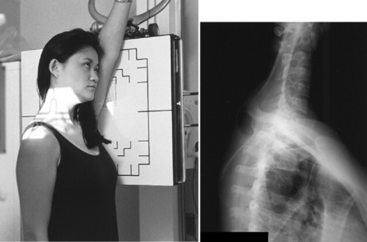
| Position: | Swimmer’s | |
| Patient Preparation: | Remove any artifacts in the desired field (e.g., clothing with hooks, snaps, zippers). Place patient in gown. | |
| Measurement: | Same as Lateral Thoracic Spine. | |
| Shielding: | Secure lead apron around patient. | |
| Film Selection: | 8 × 10 or 10 × 12 | |
| Film Placement: | Place vertically in Bucky. | |
| ID Placement: | ID should be in lower corner of collimation field. | |
| Patient Placement: | Patient can be seated or standing with arm closest to Bucky in full extension to pass alongside the ear. Shoulder nearest x-ray tube should be relaxed to its lowest point. | |
| Technique Selection: | kVp 80 to 90; mAs 80 to 120 | |
| SID: | 40″ | |
| Central Ray Placement: | The central ray enters the T1-T2 level along the midaxillary plane. | |
| Collimation: | To film size. | |
| Marker Placement: | Within the collimation field on either the right side or left side of patient depending on which lateral is performed. | |
| Breathing Instructions: | Suspend on exhalation. | |
| Anatomy Visualized: | Lower cervical and upper thoracic vertebral bodies and intervertebral disc spaces projected between the shoulders. | |
| Additional Information: | A 5-degree caudal tube tilt may help to separate the shoulders and reduce superimposition of surrounding anatomy. This view may be used when C6-C7 cannot be visualized on the lateral cervical view. | |
| ||
| Routine Chest: PA and Lateral | ||
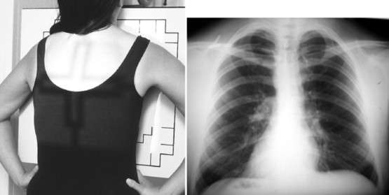
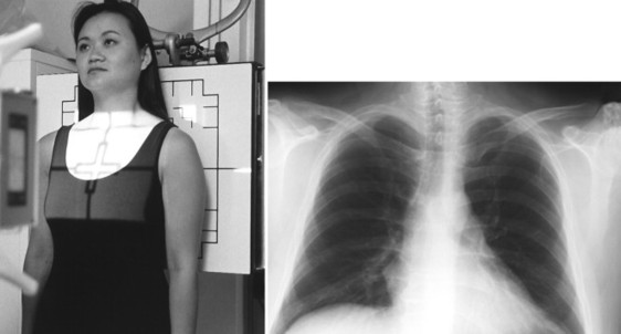
| Position: | PA Chest | |
| Patient Preparation: | Remove any artifacts in the desired field (e.g., clothing with hooks, snaps, zippers). Place patient in gown. | |
| Measurement: | Same as AP Thoracic Spine. | |
| Shielding: | Secure lead apron around patient. | |
| Film Selection: | 14 × 17 | |
| Film Placement: | Place either vertically or horizontally in Bucky depending on width of patient. The top of the cassette should be 1½ above the vertebral prominence. | |
| ID Placement: | ID should be in upper corner of collimation field. | |
| Patient Placement: | Patient is in PA position with chest against Bucky, head straight, chin slightly elevated, arms rolled forward. | |
| Technique Selection: | kVp 110 to 120; mAs 1 to 4 | |
| SID: | 72″ | |
| Central Ray Placement: | The central ray is centered to the previously placed cassette. | |
| Collimation: | To film size. | |
| Marker Placement: | Within the collimation field above the shoulder on either the right or left side. | |
| Breathing Instructions: | Deep inhalation. | |
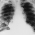
| Anatomy Visualized: | Lungs, including apices, tracheal air shadow, heart, great vessels, and diaphragm. This view also demonstrates the costophrenic angles and bony thorax. | |
| Additional Information: | The use of high kVp ensures an increased gray scale on the radiograph. | |
| Poor inspiratory efforts alter cardiothoracic ratio. One should be able to visualize the first four thoracic vertebral bodies and seven anterior ribs. | ||
| In suspected apical lesions or middle lobe infiltrates, a lordotic view may be performed to better define these areas. | ||
| If a pneumothorax is suspected, an additional view, a PA chest performed with full expiration accentuates the visceral–parietal pleural interspace. | ||
| ||
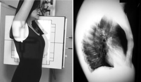
| Position: | Lateral Chest | |
| Patient Preparation: | Remove any artifacts in the desired field (e.g., clothing with hooks, snaps, zippers). Place patient in gown. | |
| Measurement: | Same as Lateral Thoracic Spine. | |
| Shielding: | Secure lead apron around patient. | |
| Film Selection: | 14 × 17 | |
| Film Placement: | Place vertically in Bucky. Top of cassette should be 1½ ″ above vertebral prominence. | |
| ID Placement: | ID should be in upper corner of collimation field. | |
| Patient Placement: | Standing with left side against Bucky with both arms in full extension raised above head. | |
| Technique Selection: | kVp 110 to 120; mAs 4 to 16 | |
| SID: | 72″ | |
| Central Ray Placement: | Central ray is centered to center of cassette. | |
| Collimation: | To film size. | |
| Marker Placement: | Within the collimation field on the side of the patient closest to the film just below the ID blocker. | |
| Breathing Instructions: | Deep inspiration. | |
| Anatomy Visualized: | Lungs, trachea, heart, great vessels, diaphragm, posterior costophrenic angles, and bony thorax. | |
| Additional Information: | The left lateral position is performed to reduce magnification of the heart shadow by having the heart closest to the film. | |
| ||
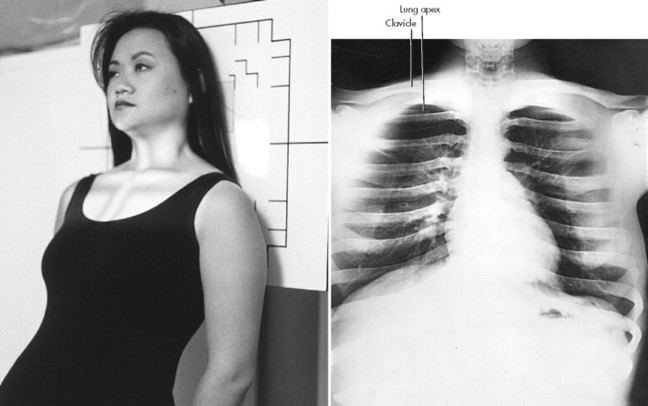
| Position: | Apical Lordotic | |
| Patient Preparation: | Remove any artifacts in the desired field (e.g., clothing with hooks, snaps, zippers). Place patient in gown. | |
| Measurement: | Same as PA Chest. | |
| Shielding: | Secure lead apron around patient. | |
| Film Selection: | 14 × 17 | |
| Film Placement: | Place vertically in Bucky. Center to central ray. | |
| ID Placement: | ID should be in lower corner of collimation field. | |
| Patient Placement: | Patient is in AP position approximately 1′ from Bucky. Patient then leans back so back of shoulders comes in direct contact with Bucky. | |
| Technique Selection: | kVp 110 to 120; mAs 1 to 4 | |
| SID: | 72″ | |
| Central Ray Placement: | Central ray enters midsternum. | |
| Collimation: | To film size. | |
| Marker Placement: | Within the collimation field on either the right side or left side of patient. | |
| Breathing Instructions: | Deep inspiration. | |
| Anatomy Visualized: | This view demonstrates the apices of the lung free of superimposition of the clavicles. This view also demonstrates interlobar effusions, if present. | |
| Additional Information: | This view may help to localize and define any lesions suspected to be posterior to the clavicle. This view also may demonstrate infiltrate in the right middle lobe. | |
| ||
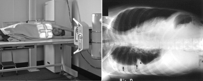
| Position: | Lateral Decubitus | |
| Patient Preparation: | Remove any artifacts in the desired field (e.g., clothing with hooks, snaps, zippers, etc.). Place patient in gown. | |
| Measurement: | Same as PA Chest. | |
| Shielding: | Secure lead apron around patient. | |
| Film Selection: | 14 × 17 | |
| Film Placement: | Place horizontally in Bucky. | |
| ID Placement: | ID should be in upper corner of collimation field. | |
| Patient Placement: | Patient is lying on affected side (e.g., right side down for right lateral decubitus, left side down for left lateral decubitus). Arms are raised above head. Patient is placed on cart or table so the shoulders are 2″ to 3″ below top of film. | |
| Technique Selection: | kVp 110 to 120; mAs 2 to 5 | |
| SID: | 72″ | |
| Central Ray Placement: | To center of previously centered cassette. | |
| Collimation: | To film size. | |
| Marker Placement: | Within the collimation field on either the right side or left side of patient. | |
| Breathing Instructions: | Deep inspiration. | |
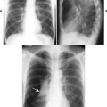
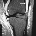
| Anatomy Visualized: | This view is performed when the patient cannot stand and pleural effusion is suspected. Because the side down is the dependent portion of the chest, small pleural effusions may be demonstrated (arrows). This view helps delineate between small pleural effusions and scar tissue formation. | |
| Additional Information: | Because pleural effusions less than 300 ccs usually cannot be seen clearly on routine PA chest radiography, decubitus films should be performed if pleural effusions are suspected. | |
| ||
| Ribs: AP or PA Unilateral or Bilateral, Above or Below Diaphragm | ||
| Position: | AP Bilateral Upper Ribs | |
| Patient Preparation: | Remove any artifacts in the desired field (e.g., clothing with hooks, snaps, zippers). Place patient in gown. | |
| Measurement: | Same as AP Thoracic Spine. | |
| Shielding: | Secure lead apron around patient. | |
| Film Selection: | 14 × 17 | |
| Film Placement: | Place transversely in Bucky. The top of the cassette should be 1½ above the vertebral prominence. | |
| ID Placement: | ID should be in lower corner of collimation field. | |
| Patient Placement: | The patient is standing in the AP position. | |
| Technique Selection: | kVp 65 to 75; mAs 20″ to 40″ | |
| SID: | 40″ | |
| Central Ray Placement: | Central ray is centered to center of cassette. | |
| Collimation: | To film size. | |
| Marker Placement: | Within the collimation field on either the right side or left side of patient. | |
| Breathing Instructions: | Suspend breathing on full inspiration. | |
| Anatomy Visualized: | Ribs above the diaphragm, especially the posterior aspect of the ribs. | |
| Additional Information: | The most common area of rib fracture is within the axillary margin of the rib, which is not clearly seen on this projection. | |
| Oblique views are required to visualize the axillary margin of the rib. | ||
| A PA chest projection should be performed to rule out pneumothorax. | ||
| ||
| Position: | AP Bilateral Lower Ribs | |
| Patient Preparation: | Remove any artifacts in the desired field (e.g., clothing with hooks, snaps, zippers). Place patient in gown. | |
| Measurement: | Measure AP through T12 area. | |
| Shielding: | Secure lead apron around patient. | |
| Film Selection: | 14 × 17 | |
| Film Placement: | Place transversely in Bucky. The bottom of the cassette is 1″ below the top of the iliac crest. | |
| ID Placement: | ID should be in upper corner of collimation field. | |
| Patient Placement: | The patient is standing in the AP position. | |
| Technique Selection: | kVp 70 to 80; mAs 30 to 60 | |
| SID: | 40″ | |
| Central Ray Placement: | The central ray is directed to the center of the cassette. | |
| Collimation: | To film size. | |
| Marker Placement: | Within the collimation field on either the right side or left side of patient. | |
| Breathing Instructions: | Suspend respiration on full exhalation. | |
| Anatomy Visualized: | Ribs below the diaphragm. | |
| Additional Information: | A computed tomography (CT) scan of the abdomen may be warranted to rule out damage to the internal organs, if a fracture of the lower ribs is suspected. | |
| ||
| Position: | AP Ribs, Unilateral | |
| Patient Preparation: | Remove any artifacts in the desired field (e.g., clothing with hooks, snaps, zippers). Place patient in gown. | |
| Measurement: | Same as AP Thoracic Spine. | |
| Shielding: | Secure lead apron around patient. | |
| Film Selection: | 14 × 17 | |
| Film Placement: | Place vertically in Bucky. The top of the cassette should be 1½ ″ above the vertebral prominence for ribs above the diaphragm. If the lower ribs are of interest, the cassette should be placed so the bottom of the cassette is 1 below the top of the iliac crest. | |
| ID Placement: | ID should be in the corner of the collimation field opposite the area of interest. | |
| Patient Placement: | The patient is standing with the midclavicular plane of the affected side centered to the center of the cassette. | |
| Technique Selection: | kVp 65 to 75; mAs 20 to 40 | |
| SID: | 40″ | |
| Central Ray Placement: | The central ray is directed to the center of the cassette. | |
| Collimation: | To film size. | |
| Marker Placement: | Within the collimation field on side of the patient that is closest to the Bucky. | |
| Breathing Instructions: | For ribs above the diaphragm, suspend respiration on full inspiration. For ribs below the diaphragm, suspend respiration on full expiration. | |
| Anatomy Visualized: | Ribs above or below the diaphragm. The view should include the area between the costovertebral joints to the axillary border of the ribs. | |
| Additional Information: | This view is performed when patient presents with rib complaints on one side only. | |
| ||
| Position: | Oblique Ribs | |
| Patient Preparation: | Remove any artifacts in the desired field (e.g., clothing with hooks, snaps, zippers). Place patient in gown. | |
| Measurement: | Same as AP Thoracic Spine. | |
| Shielding: | Secure lead apron around patient. | |
| Film Selection: | 14 × 17 | |
| Film Placement: | Place vertically in Bucky. For ribs above the diaphragm, the cassette is placed 1½ ″ above the diaphragm. For ribs below the diaphragm, the bottom of the cassette is placed 1″ below the top of the iliac crest. | |
| ID Placement: | ID should be in corner of collimation field opposite the area of interest. | |
| Patient Placement: | The patient is standing in the AP position. Rotate the patient toward affected side 45 degrees. Right-sided rib injury requires an RPO; left-sided rib injury an LPO. | |
| Technique Selection: | kVp 70 to 80; mAs 20 to 40 | |
| SID: | 40″ | |
| Central Ray Placement: | The central ray is directed to the center of the cassette just lateral to the midsternal area. | |
| Collimation: | To film size. | |
| Marker Placement: | Within the collimation field on the side of the patient that is closest to the Bucky. | |
| Breathing Instructions: | For ribs above the diaphragm, suspend respiration on full inhalation. For ribs below the diaphragm, suspend respiration on full exhalation. | |
| Anatomy Visualized: | Axillary margin of ribs on the affected side. | |
| Additional Information: | ||