Embryology
The fertilized ovum migrates down the uterine tube and implants itself on the uterine mucosa. Implantation is followed by a period of rapid mitosis, passing through morula, blastocyst, and two-layer (endoderm and ectoderm) embryonic disc stages. A portion of the ectoderm extends ventrally, proliferates, and gives rise to the mesoderm, which separates the endoderm and ectoderm.
The neural plate of the ectoderm involutes to form the neural tube (future spinal cord). A rod of cells, known as the notochord, is situated between the developing gut and neural tube. The notochord guides the development of the spine.
The dorsal portion of the mesoderm located on either side of the notochord begins to condense and segment into 42 to 44 pairs of somites (four occipital, eight cervical, twelve thoracic, five lumbar, five sacral, and eight to ten coccygeal). Within each somite, cells exist that form the sclerotomal tissues (bone and dense connective tissues). These cells are guided by the notochord to form the vertebrae and ribs with further lateral migration to form the limb buds and extremities. The sclerotomal cells forming the vertebral bodies develop intervertebral fissures filled with mesenchyme that become the intervertebral disc. The notochordal elements within the disc become the nucleus pulposus. The somite also gives rise to myotomal (muscles) and dermatomal (dermis) structures.
Bone
BONE DEVELOPMENT
Bone functions to protect and support the body. Bone is a connective tissue and is composed of fibers, cells, and noncellular matrix material (ground substance). Bone is truly a remarkable substance that offers high tensile and compressive strength while maintaining some degree of elasticity. Bone is a relatively lightweight and resilient tissue. Contrary to popular belief, bone is not dead; it is highly dynamic and metabolically active. Bone provides a storehouse of calcium, phosphorus, and other minerals. It is constantly remodeling; atrophy occurs in areas of understress and hypertrophy in areas of overstress.
BONE COMPOSITION
Like any connective tissue, bone is composed of cells and matrix. The matrix is composed of fibers, inorganic salts, and ground substance. The fibers are mostly collagen; elastic fibers are minimal. Collagen fibers are present to a greater degree than in other tissues, giving bone strength and resiliency. Organic salts give bone hardness and rigidity. Organic salts are present in crystal as hydroxyapatite crystals, a form of calcium phosphate. The ground substance consists of glycosaminoglycans (GAGs), namely, chondroitin sulfate, keratan sulfate, and hyaluronic acid.
BONE FORMATION
The cellular constituents and chemical reactions are the same for all bones formed in the body. Bone always forms by replacing some other preexisting material. The histogenesis of bone is dichotomized into bones that form in preexisting cartilage and bones that form from preexisting embryonic mesenchyme. The two types of bone production are not mutually exclusive. Both processes often occur within the same bone. For instance, the femoral bone is lengthened by enchondral bone formation at its metaphyses, but increased width of the bone occurs from intermembranous bone in the periosteum.
Enchondral ossification.
Enchondral bone formation represents bones formed in a hyaline cartilage template. This is the most common method by which bones form. Examples include the femur, tibia, vertebrae, and metacarpals. The process begins in centers of ossification located in the embryonic skeleton and continues into the late teen years. Lengthening of the bone occurs in the epiphyseal growth plate. Cells on the metaphyseal side ossify (zone of provisional calcification), and cells on the epiphyseal side multiply (zone of proliferation).
Intermembranous ossification.
Intermembranous bone formation occurs when embryonic mesenchyme condenses into highly vascular connective tissue, which produces a thin layer of matrix and collagen. Peripheral connective tissue cells differentiate into osteoblasts, which produce additional matrix and collagen. Calcification of the matrix occurs, trapping the osteoblasts within the newly formed bone, thereby converting them to osteocytes. Examples include the mandible and bones of the cranium.
BONE STRUCTURE
Macroscopic structure.
Inspection of a longitudinal section of a long bone reveals two different types of bone structure: compact (substantia compacta) and spongy (substantia spongiosa), or cancellous, bone. Compact bone is found at the outer border of a bone; cancellous bone is the latticelike network within a bone. Both compact and cancellous bone are lamellar. Woven bone represents immature bone, which is replaced with lamellar bone over time.
In the immature skeleton, epiphyses are separated from the shaft of the long bone by a thin, cartilaginous epiphyseal plate. Cartilaginous epiphyseal plates are attached to the bony diaphysis by a transitional region, known as the metaphysis. The epiphysis and portions of the metaphysis contain a lattice of small bone spicules known as trabeculae.
In the adult, once the cartilaginous plates ossify, the medullary cavity of the diaphysis is continuous with the intertrabecular spaces of the metaphysis and epiphysis. At each end of the bone, a thin layer of articular cartilage covers the thin cortex of the epiphyses.
The periosteum represents a specialized connective tissue that covers the bone. It is composed of two layers: an inner layer that has the ability to form bone through intramembranous ossification, and an outer fibrous layer that anchors into the compact bone by Sharpey’s fibers. Periosteum does not cover the ends of the bone in which articular cartilage exists, nor does it extend under joint capsules. The femoral neck and talus are examples of bone structures that lack periosteum. Fractures in these areas heal more precariously because of the absence of the osteogenic capabilities of the inner layer of the periosteum. Periosteum is also absent on bones formed within tendons (e.g., sesamoids, patella) and at ligament and tendon insertions.
The medullary cavity and interspaces of the cancellous bone are lined with endosteum. Endosteum lacks the tough fibrous nature of the periosteum, but, similar to the periosteum, it possesses osteogenic properties.
In the flat bones of the skull, the cortex forms two thick layers of bone (inner and outer table), which sandwich an interposed layer of spongy bone (diploë). The periosteum is known as pericranium, and the inner surface of the bone is lined by dura mater.
Microscopic structure
Compact bone.
The basic anatomic unit of compact bone is the osteon. An osteon consists of 4 to 20 lamellae surrounding a central osteonal canal. Osteocytes are located within lacunae found between adjacent lamellae. Adjacent osteocytes communicate through tiny canals extending radially from the lacunae, known as canaliculi. Blood vessels are found in the osteonal canals with radial branches extending through lateral canals to reach the periphery of the osteon. Between each osteon are partially resorbed or restructured osteons known as interstitial systems.
Cancellous bone.
Cancellous bone does not form an orderly osteon, as in compact bone. Cancellous bone is found in sheets or layers. Osteocytes are found in lacunae orderly aligned in rows. Osteocytes are nourished by nutrient diffusion through canaliculi. An osteonal system is not needed because of the proximity of the rich blood supply in the bone marrow.
Cells.
Osteoblasts form bone; they produce the matrix and collagen fibers. Once the bone is formed, osteoblasts become trapped and are known as osteocytes. Osteoclasts are large multinucleated cells responsible for the breakdown of bone by secreting osteolytic enzymes.
Joints
Joints, or articulations, represent connections between adjacent skeletal structures. The connections are maintained by connective tissues. The movement of the joint is largely dependent upon its structure and the nature of surrounding connective tissues. Joints are classified by either their degree of motion or the type of intervening connective tissue (Table 6-1).
| Classification | Description | Examples |
|---|---|---|
| Function | ||
| Synarthrosis | Fixed joints, no motion | Skull sutures |
| Amphiarthrosis | Deformable joints, slight motion | Intervertebral disc |
| Diarthrosis | Free joints, wide range of motion | Knee |
| Structure | ||
| Fibrous | Apposing elements are connected by fibrous tissue; no joint cavity | Skull sutures, teeth |
| Cartilaginous | Apposing elements are connected by hyaline cartilage (synchondrosis) or fibrocarcartilage (symphysis); no joint space | Costochondral, intervertebral disc |
| Synovial | Apposing elements are separated by a joint space, surrounded by a fibrous joint capsule, may contain articular disc or meniscus, and are lined by a synovial membrane | Knee, ankle, elbow |
Anatomic Figures
FIG. 6-1FIG. 6-2FIG. 6-3FIG. 6-4FIG. 6-5FIG. 6-6FIG. 6-7FIG. 6-8FIG. 6-9FIG. 6-10FIG. 6-11FIG. 6-12FIG. 6-13FIG. 6-14FIG. 6-15FIG. 6-16FIG. 6-17FIG. 6-18FIG. 6-19FIG. 6-20FIG. 6-21FIG. 6-22FIG. 6-23FIG. 6-24FIG. 6-25FIG. 6-26FIG. 6-27FIG. 6-28FIG. 6-29FIG. 6-30FIG. 6-31FIG. 6-32FIG. 6-33FIG. 6-34FIG. 6-35FIG. 6-36FIG. 6-37FIG. 6-38FIG. 6-39FIG. 6-40FIG. 6-41FIG. 6-42FIG. 6-43FIG. 6-44FIG. 6-45FIG. 6-46FIG. 6-47FIG. 6-48FIG. 6-49FIG. 6-50FIG. 6-51FIG. 6-52FIG. 6-53FIG. 6-54FIG. 6-55FIG. 6-56FIG. 6-57FIG. 6-58FIG. 6-59FIG. 6-60FIG. 6-61FIG. 6-62FIG. 6-63FIG. 6-64FIG. 6-65FIG. 6-66FIG. 6-67FIG. 6-68FIG. 6-69FIG. 6-70FIG. 6-71FIG. 6-72FIG. 6-73FIG. 6-74FIG. 6-75FIG. 6-76FIG. 6-77FIG. 6-78FIG. 6-79FIG. 6-80FIG. 6-81FIG. 6-82FIG. 6-83FIG. 6-84FIG. 6-85FIG. 6-86FIG. 6-87FIG. 6-88FIG. 6-89FIG. 6-90FIG. 6-91FIG. 6-92FIG. 6-93FIG. 6-94FIG. 6-95FIG. 6-96FIG. 6-97FIG. 6-98FIG. 6-99FIG. 6-100FIG. 6-101FIG. 6-102FIG. 6-103FIG. 6-104FIG. 6-105FIG. 6-106FIG. 6-107FIG. 6-108FIG. 6-109FIG. 6-110FIG. 6-111FIG. 6-112FIG. 6-113FIG. 6-114FIG. 6-115FIG. 6-116FIG. 6-117FIG. 6-118FIG. 6-119FIG. 6-120FIG. 6-121FIG. 6-122FIG. 6-123FIG. 6-124FIG. 6-125FIG. 6-126FIG. 6-127FIG. 6-128FIG. 6-129FIG. 6-130FIG. 6-131FIG. 6-132FIG. 6-133FIG. 6-134FIG. 6-135FIG. 6-136FIG. 6-137FIG. 6-138FIG. 6-139FIG. 6-140FIG. 6-141FIG. 6-142FIG. 6-143FIG. 6-144FIG. 6-145FIG. 6-146FIG. 6-147FIG. 6-148 and FIG. 6-149 present normal anatomy of the brain, spine, thorax, and extremities. Plain film radiography and advanced imaging with magnetic resonance imaging and computed tomography are used. The images are presented in anatomic position, with the reader viewing the anterior aspect of the patient in face-to-face orientation.
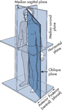 |
| FIG. 6-1 Planes of the body. (From Ballinger PW: Merrill’s atlas of radiographic positioning and radiologic procedures, ed 8, St Louis, 1995, Mosby.) |
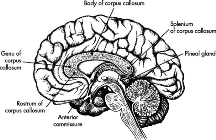 |
| FIG. 6-2 Sagittal view of cerebral cortex. (From Kelley LL: Sectional anatomy for imaging professionals, St Louis, 1997, Mosby.) |
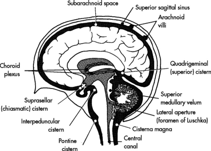 |
| FIG. 6-3 Sagittal view of choroid plexus and cisterns of ventricular system. (From Kelley LL: Sectional anatomy for imaging professionals, St Louis, 1997, Mosby.) |
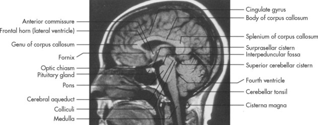 |
| FIG. 6-4 Sagittal T1-weighted magnetic resonance imaging scan at the midsagittal level. (From Haaga JR: CT and MRI of the whole body, ed 4, vol 1, St Louis, 2003, Mosby.) |
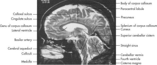 |
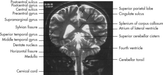
| FIG. 6-5 Sagittal T2-weighted magnetic resonance imaging scan at the midsagittal level. (From Haaga JR: CT and MRI of the whole body, ed 4, vol 1, St Louis, 2003, Mosby.) |
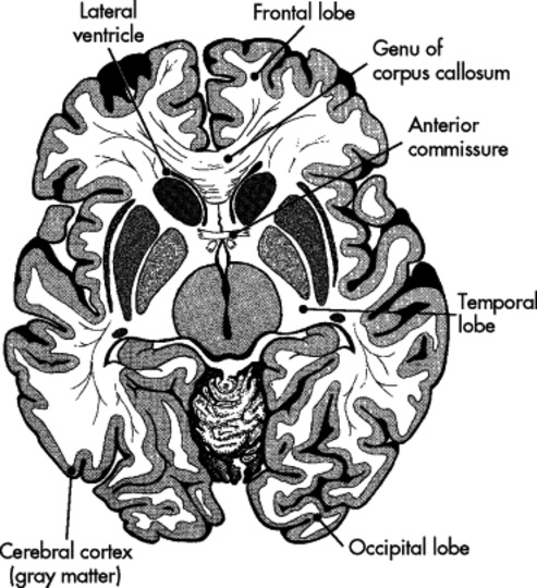 |
| FIG. 6-6 Axial view of cerebral cortex and corpus callosum. (From Kelley LL: Sectional anatomy for imaging professionals, St Louis, 1997, Mosby.) |
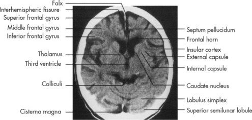 |
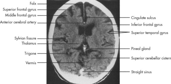
| FIG. 6-7 Enhanced axial computed tomography scan at the third ventricular level. (From Haaga JR: CT and MRI of the whole body, ed 4, vol 1, St Louis, 2003, Mosby.) |
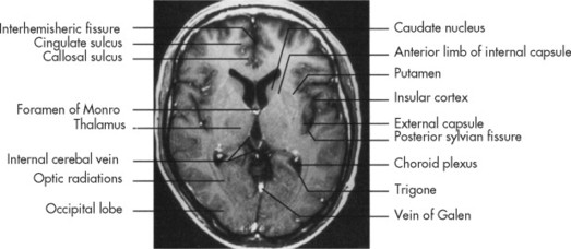 |
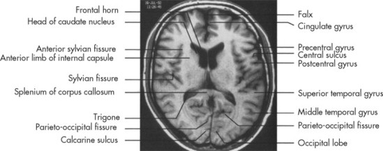
| FIG. 6-8 Axial T1-weighted magnetic resonance imaging scan at the third ventricular level. (From Haaga JR: CT and MRI of the whole body, ed 4, vol 1, St Louis, 2003, Mosby.) |
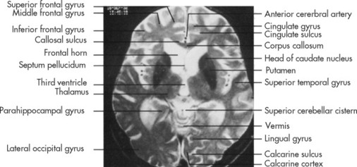 |
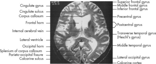
| FIG. 6-9 Axial T2-weighted magnetic resonance imaging scan at the third ventricular level. (From Haaga JR: CT and MRI of the whole body, ed 4, vol 1, St Louis, 2003, Mosby.) |
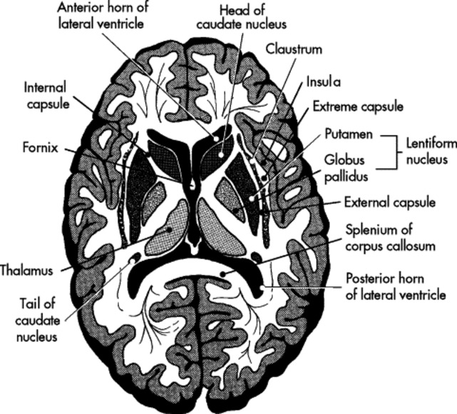 |
| FIG. 6-10 Axial view of basal ganglia. (From Kelley LL: Sectional anatomy for imaging professionals, St Louis, 1997, Mosby.) |
 |
| FIG. 6-11 Enhanced axial computed tomography scan at the low ventricular level. (From Haaga JR: CT and MRI of the whole body, ed 4, vol 1, St Louis, 2003, Mosby.) |
 |
| FIG. 6-12 Axial T1-weighted magnetic resonance imaging scan at the low ventricular level, slightly above the computed tomography scan level. (From Haaga JR: CT and MRI of the whole body, ed 4, vol 1, St Louis, 2003, Mosby.) |
 |
| FIG. 6-13 Axial T2-weighted magnetic resonance imaging scan at the low ventricular level, slightly above the computed tomography scan level. (From Haaga JR: CT and MRI of the whole body, ed 4, vol 1, St Louis, 2003, Mosby.) |
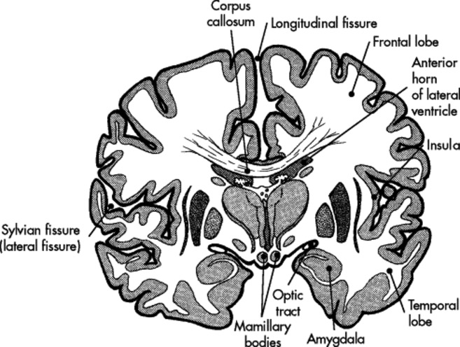 |
| FIG. 6-14 Coronal view of cerebral lobes and insula. (From Kelley LL: Sectional anatomy for imaging professionals, St Louis, 1997, Mosby.) |
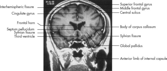 |
| FIG. 6-15 Coronal T1-weighted magnetic resonance imaging scan at the level of the frontal horns. (From Haaga JR: CT and MRI of the whole body, ed 4, vol 1, St Louis, 2003, Mosby.) |
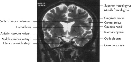 |
| FIG. 6-16 Coronal T2-weighted magnetic resonance imaging scan at the level of the frontal horns. (From Haaga JR: CT and MRI of the whole body, ed 4, vol 1, St Louis, 2003, Mosby.) |
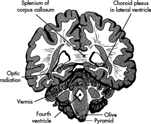 |
| FIG. 6-17 Coronal view of medulla oblongata.a (From Kelley LL: Sectional anatomy for imaging professionals, St Louis, 1997, Mosby.) |
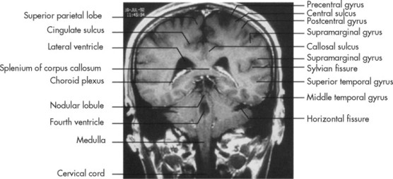 |
| FIG. 6-18 Coronal T1-weighted magnetic resonance imaging scan at the mid-to-posterior ventricular level. (From Haaga JR: CT and MRI of the whole body, ed 4, vol 1, St Louis, 2003, Mosby.) |
 |
| FIG. 6-19 Coronal T2-weighted magnetic resonance imaging scan at the mid-to-posterior ventricular level. (From Haaga JR: CT and MRI of the whole body, ed 4, vol 1, St Louis, 2003, Mosby.) |
 |
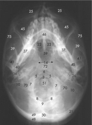
| FIG. 6-26 |
 |
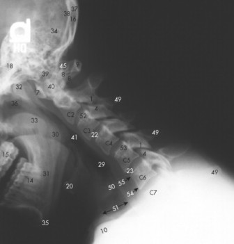
| FIG. 6-27 |
 |
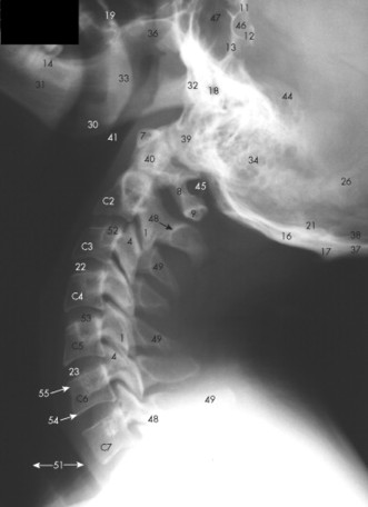
| FIG. 6-28 |
 |
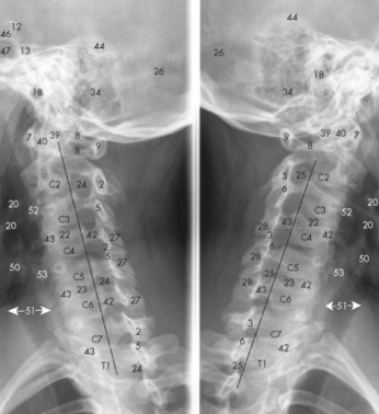
| FIG. 6-29 |
 |
| FIG. 6-30 |
 |
| FIG. 6-31 |
 |
| FIG. 6-34 |
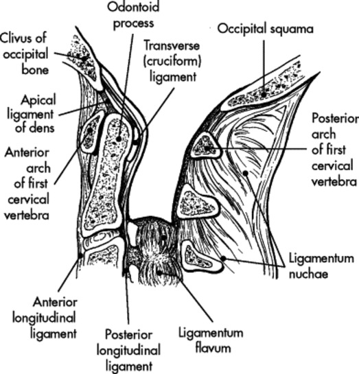 |
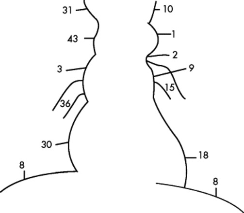
| FIG. 6-35 Median section of cervical spine demonstrating spinal ligaments. (From Kelley LL: Sectional anatomy for imaging professionals, St Louis, 1997, Mosby.) |
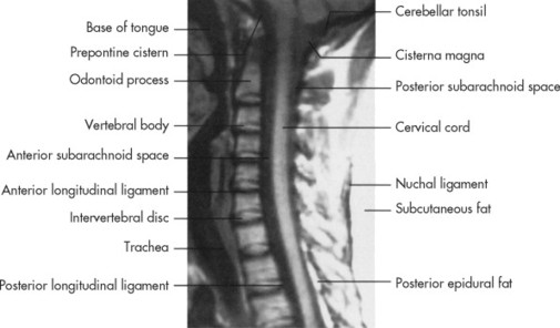 |
| FIG. 6-36 Sagittal T1-weighted magnetic resonance imaging of cervical spine. (From Haaga JR: CT and MRI of the whole body, ed 4, vol 1, St Louis, 2003, Mosby.) |
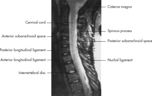 |
| FIG. 6-37 Sagittal gradient echo study of cervical spine showing increased signal intensity of cerebrospinal fluid, similar to that in a T2-weighted study. (From Haaga JR: CT and MRI of the whole body, ed 4, vol 1, St Louis, 2003, Mosby.) |
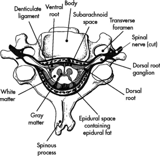 |
| FIG. 6-38 Axial section of spinal cord. (From Kelley LL: Sectional anatomy for imaging professionals, St Louis, 1997, Mosby.) |
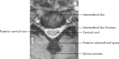 |
| FIG. 6-39 Axial gradient echo magnetic resonance imaging scan through the intervertebral foramen in the midcervical region. (From Haaga JR: CT and MRI of the whole body, ed 4, vol 1, St Louis, 2003, Mosby.) |
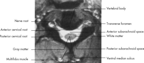 |
| FIG. 6-40 Axial gradient echo magnetic resonance imaging scan in the midcervical region, just caudal to the image shown in Figure 6-39. (From Haaga JR: CT and MRI of the whole body, ed 4, vol 1, St Louis, 2003, Mosby.) |
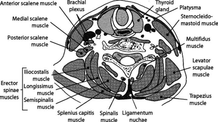 |
| FIG. 6-41 Axial section of cervical vertebra with musculature. (From Kelley LL: Sectional anatomy for imaging professionals, St Louis, 1997, Mosby.) |
 |
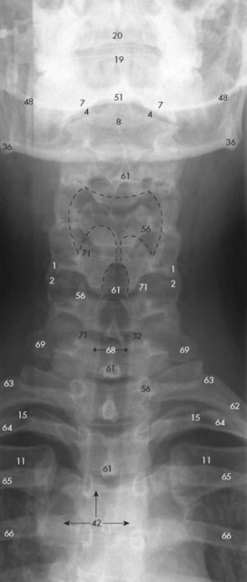
| FIG. 6-42 Axial computed tomography scan through a cervical vertebral body. (From Haaga JR: CT and MRI of the whole body, ed 4, vol 1, St Louis, 2003, Mosby.) |
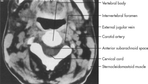 |
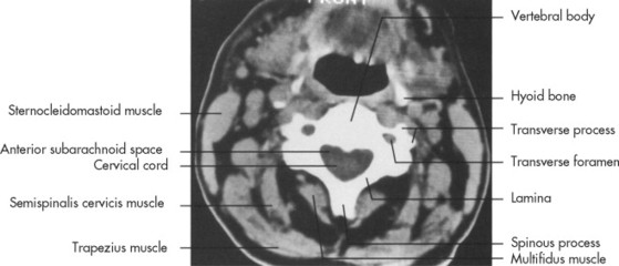
| FIG. 6-43 Axial computed tomography scan through the intervertebral foramen in the midcervical region. (From Haaga JR: CT and MRI of the whole body, ed 4, vol 1, St Louis, 2003, Mosby.) |
 |
| FIG. 6-44 |
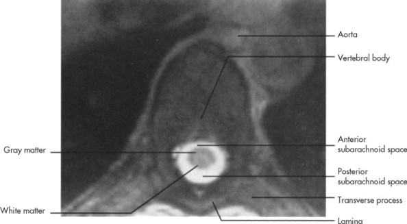 |
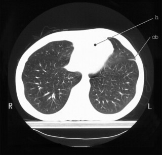
| FIG. 6-47 Axial T2-weighted magnetic resonance imaging at the midthoracic level. (From Haaga JR: CT and MRI of the whole body, ed 4, vol 1, St Louis, 2003, Mosby.) |
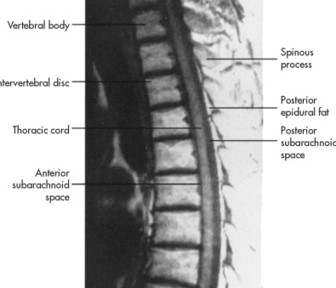 |
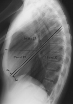
| FIG. 6-48 Sagittal T1-weighted magnetic resonance imaging study of the thoracic spine. (From Haaga JR: CT and MRI of the whole body, ed 4, vol 1, St Louis, 2003, Mosby.) |
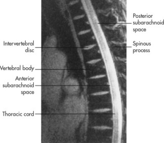 |
| FIG. 6-49 Sagittal T2-weighted magnetic resonance imaging study of the thoracic spine. (From Haaga JR: CT and MRI of the whole body, ed 4, vol 1, St Louis, 2003, Mosby.) |
 |
| FIG. 6-50 |
 |
| FIG. 6-51 (From Kelley LL: Sectional anatomy for imaging professionals, St. Louis, 1997, Mosby.) |
 |
| FIG. 6-52 |
 |
| FIG. 6-53 |
 |
| FIG. 6-54 |
 |
| FIG. 6-55 |
 |
| FIG. 6-56 |
 |
| FIG. 6-57 (From Kelley LL: Sectional anatomy for imaging professionals, St. Louis, 1997, Mosby.) |
 |
| FIG. 6-58 (From Kelley LL: Sectional anatomy for imaging professionals, St Louis, 1997, Mosby.) |
 |
| FIG. 6-59 (From Kelley LL: Sectional anatomy for imaging professionals, St Louis, 1997, Mosby.) |
 |
| FIG. 6-60 (From Kelley LL: Sectional anatomy for imaging professionals, St Louis, 1997, Mosby.) |
 |
| FIG. 6-61 (From Kelley LL: Sectional anatomy for imaging professionals, St Louis, 1997, Mosby.) |
 |
| FIG. 6-62 (From Kelley LL: Sectional anatomy for imaging professionals, St Louis, 1997, Mosby.) |
 |
| FIG. 6-63 (From Kelley LL: Sectional anatomy for imaging professionals, St Louis, 1997, Mosby.) |
 |
| FIG. 6-64 (From Kelley LL: Sectional anatomy for imaging professionals, St Louis, 1997, Mosby.) |
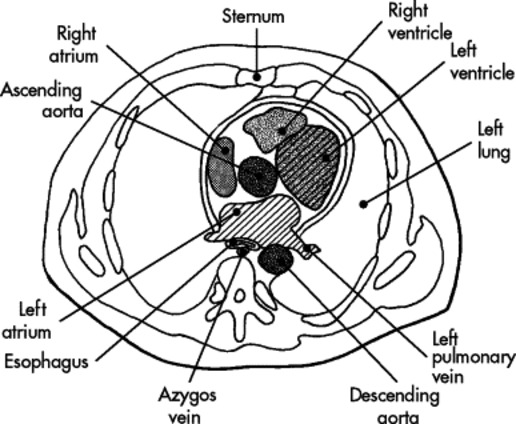 |
| FIG. 6-65 Axial view of the heart with four chambers. (From Kelley LL: Sectional anatomy for imaging professionals, St Louis, 1997, Mosby.) |
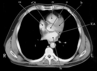 |
| FIG. 6-66 (From Kelley LL: Sectional anatomy for imaging professionals, St Louis, 1997, Mosby.) |
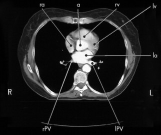 |
| FIG. 6-67 (From Kelley LL: Sectional anatomy for imaging professionals, St Louis, 1997, Mosby.) |
 |
| FIG. 6-68 |
 |
| FIG. 6-70 |
 |
| FIG. 6-71 |
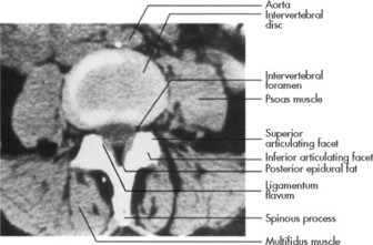 |
| FIG. 6-72 Axial computed tomography scan through the intervertebral disc in the midlumbar region in a narrow window setting. (From Haaga JR: CT and MRI of the whole body, ed 4, vol 1, St Louis, 2003, Mosby.) |
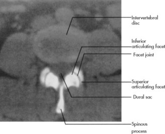 |
| FIG. 6-73 Axial computed tomography scan through the intervertebral disc in a wide window setting. (From Haaga JR: CT and MRI of the whole body, ed 4, vol 1, St Louis, 2003, Mosby.) |
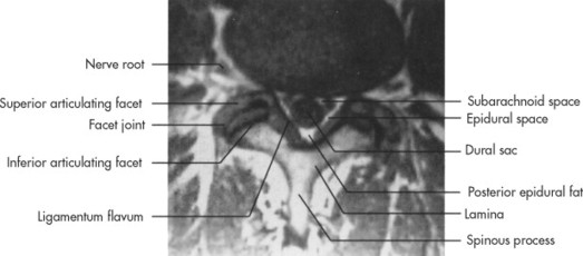 |
| FIG. 6-74 Axial T1-weighted magnetic resonance imaging through the facet joints. (From Haaga JR: CT and MRI of the whole body, ed 4, vol 1, St Louis, 2003, Mosby.) |
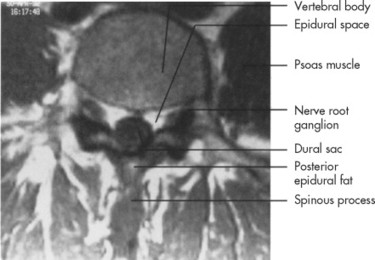 |
| FIG. 6-75 Axial T1-weighted magnetic resonance imaging through the midportion of the vertebral body in the lumbar region. (From Haaga JR: CT and MRI of the whole body, ed 4, vol 1, St Louis, 2003, Mosby.) |
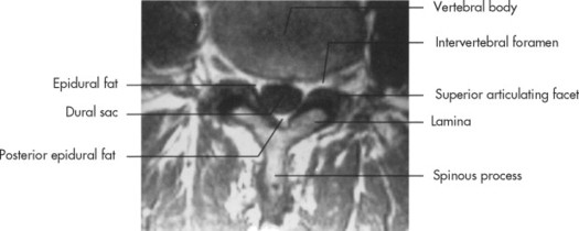 |
| FIG. 6-76 Axial T1-weighted magnetic resonance imaging of fat in the epidural space. (From Haaga JR: CT and MRI of the whole body, ed 4, vol 1, St Louis, 2003, Mosby.) |
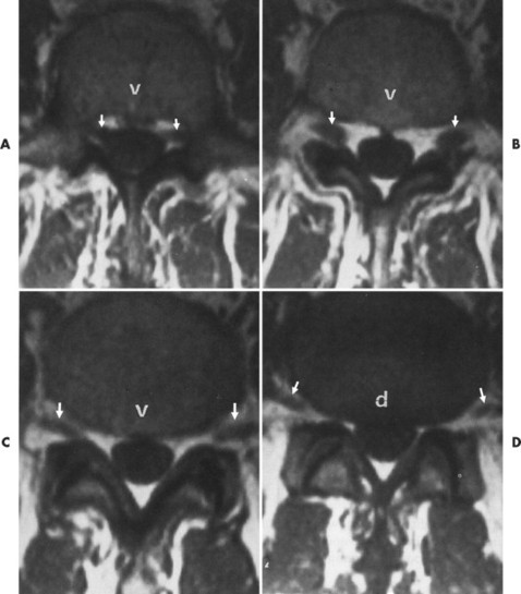 |
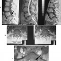
| FIG. 6-77 Axial T1-weighted magnetic resonance imaging depicts the path of lumbar nerve roots through the canal; d, disc; v, vertebral body. A, At the midbody level, the preexisting roots (arrows) are positioned in the lateral recesses. B and C, Just inferior to A at the superior aspect of the discovertebral junction, the roots lie within the foramina (arrows). D, At the inferior aspect of the discovertebral junction, the roots have already exited the foramina (arrows). (From Haaga JR: CT and MRI of the whole body, ed 4, vol 1, St Louis, 2003, Mosby.) |
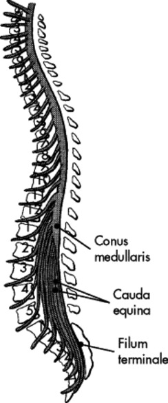 |
| FIG. 6-78 Sagittal section of conus medullaris, cauda equina, and filum terminale. (From Kelley LL: Sectional anatomy for imaging professionals, St Louis, 1997, Mosby.) |
 |
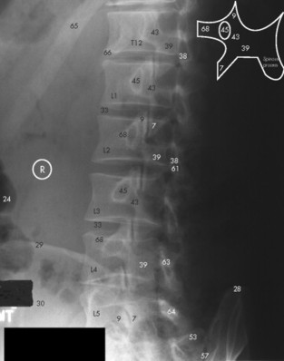
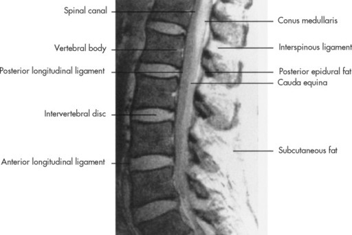
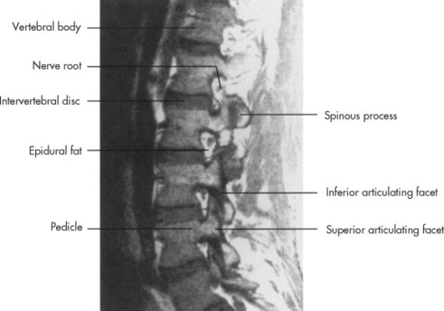
| FIG. 6-79 Sagittal T1-weighted magnetic resonance imaging study of the lumbar spine in midline. (From Haaga JR: CT and MRI of the whole body, ed 4, vol 1, St Louis, 2003, Mosby.) |
 |
| FIG. 6-80 Sagittal gradient echo magnetic resonance imaging study of the lumbar spine in midline. (From Haaga JR: CT and MRI of the whole body, ed 4, vol 1, St Louis, 2003, Mosby.) |
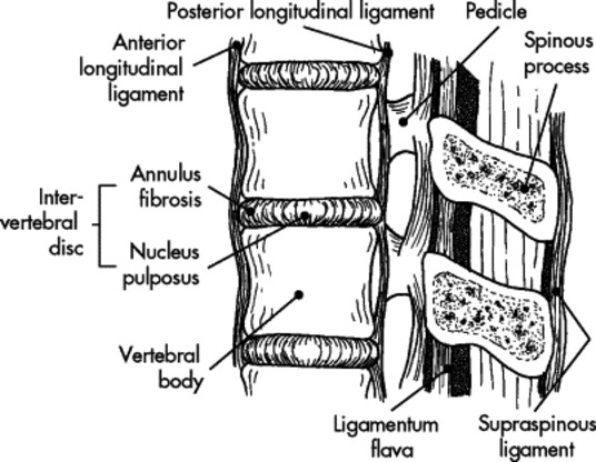 |
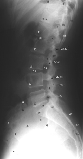
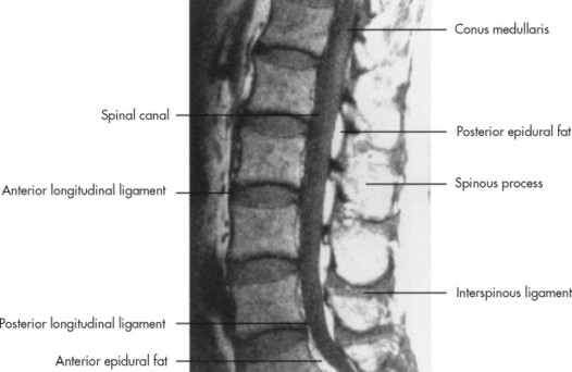
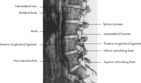
| FIG. 6-81 Sagittal section of the lumbar spine with spinal ligaments. (From Kelley LL: Sectional anatomy for imaging professionals, St Louis, 1997, Mosby.) |
 |
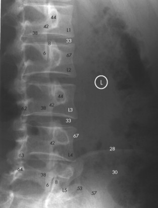
| FIG. 6-82 Para-midline sagittal T1-weighted magnetic resonance imaging study of the lumbar spine. (From Haaga JR: CT and MRI of the whole body, ed 4, vol 1, St Louis, 2003, Mosby.) |
 |
| FIG. 6-83 Para-midline sagittal T2-weighted magnetic resonance imaging study of the lumbar spine. (From Haaga JR: CT and MRI of the whole body, ed 4, vol 1, St Louis, 2003, Mosby.) |
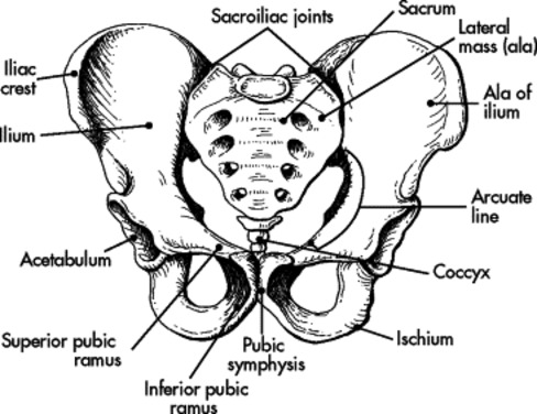 |
| FIG. 6-84 Anterior view of the pelvis. (From Kelley LL: Sectional anatomy for imaging professionals, St Louis, 1997, Mosby.) |
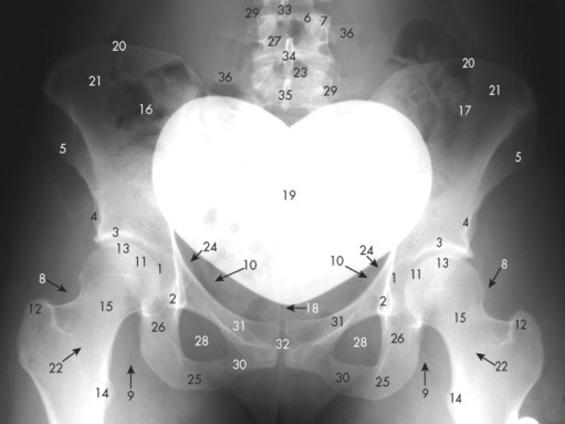 |
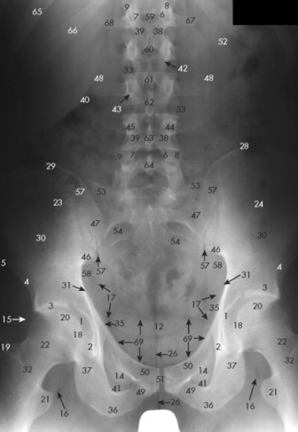
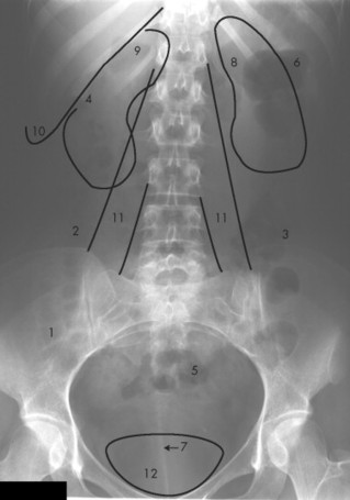
| FIG. 6-85 Anteroposterior pelvic radiograph. (See Key for Figure 6-85.) |
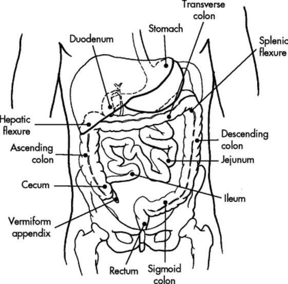 |
| FIG. 6-88 Anterior view of the intestines. (From Kelley LL: Sectional anatomy for imaging professionals, St Louis, 1997, Mosby.) |
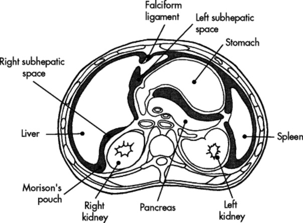 |
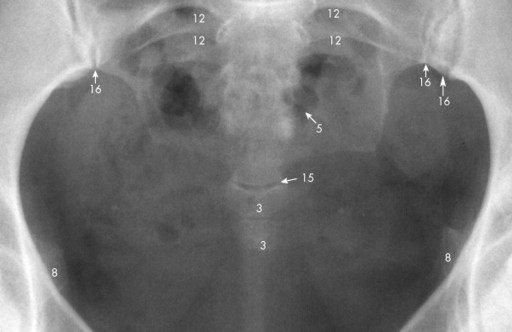
| FIG. 6-89 Axial view of the subhepatic spaces and Morison’s pouch. (From Kelley LL: Sectional anatomy for imaging professionals, St Louis, 1997, Mosby.) |
 |
| FIG. 6-90 |
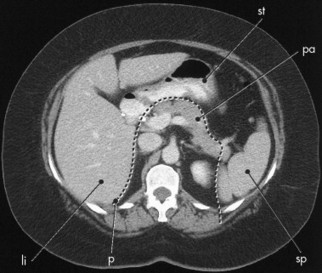 |
FIG. 6-91 Related posts:Stay updated, free articles. Join our Telegram channel
Full access? Get Clinical Tree
 Get Clinical Tree app for offline access

|