Chapter 25 Accident and emergency
The role of the radiographer in the multidisciplinary team
The progression of highlighting abnormalities through the use of a ‘red dot’ system1 has been well documented, and by 2004 a national survey showed that 81% of hospital trusts/boards were using this aspect of role development.2 Alongside this, the development of the advanced trauma and life support (ATLS)3 approach to dealing with the patient with multiple injuries and the inception of the four-tier system4 of working in the UK have advanced the position of the radiographer within the accident and emergency (A&E) multidisciplinary team. Gradual development of service provision through advanced training, to create the reporting radiographer, has further ensured the value of this team member in the A&E department.
The role of the reporting radiographer has ensured that an invaluable service can now be provided instantly in the A&E department. Acting as report writer, advanced A&E imaging practitioner, advisor to junior radiographic staff or students and other professionals in the multidisciplinary team, the reporting radiographer keys in neatly with (at a minimum) the advanced practitioner or consultant practitioner level of the ‘four-tier’ system of work that has evolved during the first part of the 21st century. Moving forward with this, the current recommendations are for radiographers to give an initial interpretation of their image by issuing a comment;5 this aspect will be discussed later in this chapter.
It is not only in the ATLS situation that the radiographer will display the versatility to cope with the demands of the varied A&E patient presentations, across widely ranging age groups and varying requirements for adaptation of techniques. The radiographer also displays their value to the multidisciplinary team for all A&E cases in which they are involved. However, admitting a lack of knowledge or ability should not be seen as a suggestion of general inability; examples of this are most likely to lie in unusual circumstances, difficult patient presentations or difficulty with highlighting perceived abnormalities. Admission of lack of knowledge or ability, and acceptance that another more experienced or skilled member of the team may provide a better service, is the most responsible and appropriate action for this situation. This may be reflected in discussing A&E images, or requests for imaging, with the referrer or radiologist so that the best patient outcome may be achieved. Also, knowledge and its application in the form of advising alternative imaging, perhaps with a protocol-driven application of the Ionising Radiation (Medical Exposure) Regulations [IR(ME)R 2006],6 is further evidence of the extended service provision of the radiographer within the multidisciplinary team. Indeed, acting as a gatekeeper of ionising radiation exposure to the general public is one of the more demanding roles, expected even of the newly qualified radiographer.
It is necessary that the radiography professional understands the following:
• Most common injury presentations associated with trauma mechanisms
• How trauma mechanism and presentation may influence projection or technique selection
• How trauma mechanism and presentation may influence technique adaptation, in varied situations
The team role of the radiographer: image interpretation
The ‘red dot’7 system has become an accepted norm for the practising radiographer and features in many undergraduate radiography courses in the UK, along with a move towards providing initial comment on images.
• Correct area included (on all projections)
• Correct radiographic position
• Adequate exposure factors used (for contrast, density and sharpness)
• Assess the whole area,8 avoiding the urge to focus on the ‘obvious’
• Examine the cortical outline and trabecular pattern8,9 (follow the outline of the bone, assess for disruption)
• Look at the soft tissue9,10 (any change may indicate a subtle fracture)
• Check radiographic lines, zones and arcs10 (for this the radiographer needs to be aware of the basics and how to use them)
It may be difficult to ascertain the medicolegal position of a commenting system unless a test case were to be presented. Even if a radiographer is not held responsible in civil proceedings, there is no reason why disciplinary or professional conduct hearings would not find the radiographer guilty of negligent conduct in situations relating to comments on anatomical appearances, if the employer has implemented a suitable framework for a commenting scheme. Vicarious liability by the employing hospital trust expects reasonable standards of care to have been exercised when supporting its employees in the execution of their duties. This includes operating within recognised protocols, working to professional standards, and also, on the part of the employer, the provision of appropriate educational support and safe working practices agreed by all participants.11
Similarly, radiographers who provide a reporting service, and have necessarily undergone significant postgraduate education, should offer the same standard of report; it is not acceptable to provide a lower standard of report simply because they are not radiologists.12
The team role of the radiographer: suitable equipment choice
Experience also plays a significant role in the activities of service provision, especially on the ancillary equipment selection front. Frequently, this type of equipment for support to the A&E imaging department is often selected without including the radiographer in the purchasing exercise. As an example, the choice of trolleys that are widely used across disciplines often results in difficulties not only for radiology staff but also for the patient and the wider team in the A&E department. In the end, a poor-quality service is often delivered because of a lack of foresight in operating as a cohesive team. Holistic care demands cooperation across boundaries seen as traditional divides; however, borders are created where they are inappropriate.4 This is a particular problem where professions that form the minority in an area of operation are perceived as lacking in appreciation for what is best for that department area or the patient. Advocacy for the patient and service can take many different forms that are frequently not recognised.
Mechanisms of injury
A range of reasons exists as to why patients present in A&E. Certain patterns of trauma present themselves time and again, i.e. the ‘common occurrences’, although some injuries present after apparently minor trauma or as a result of seemingly ridiculous circumstances. Probably the most famous of all causes of injury is the ‘fall onto outstretched hand’ or FOOSH. Another commonly encountered trauma involves twisting of the ankle, which generates injury patterns which are linked, as force is transmitted along the whole of the leg. Certain age groups, because of their involvement in specific activities, or alternatively as a result of pathological processes influencing bone integrity, display unexpectedly severe presentations of injury following apparently innocuous trauma forces. Table 25.1 attempts to draw together injuries linked to the mechanism so that potential plain film skeletal imaging projections can be determined and expected injury patterns anticipated.
Further projections and adapted techniques
Adapted projections of the hand
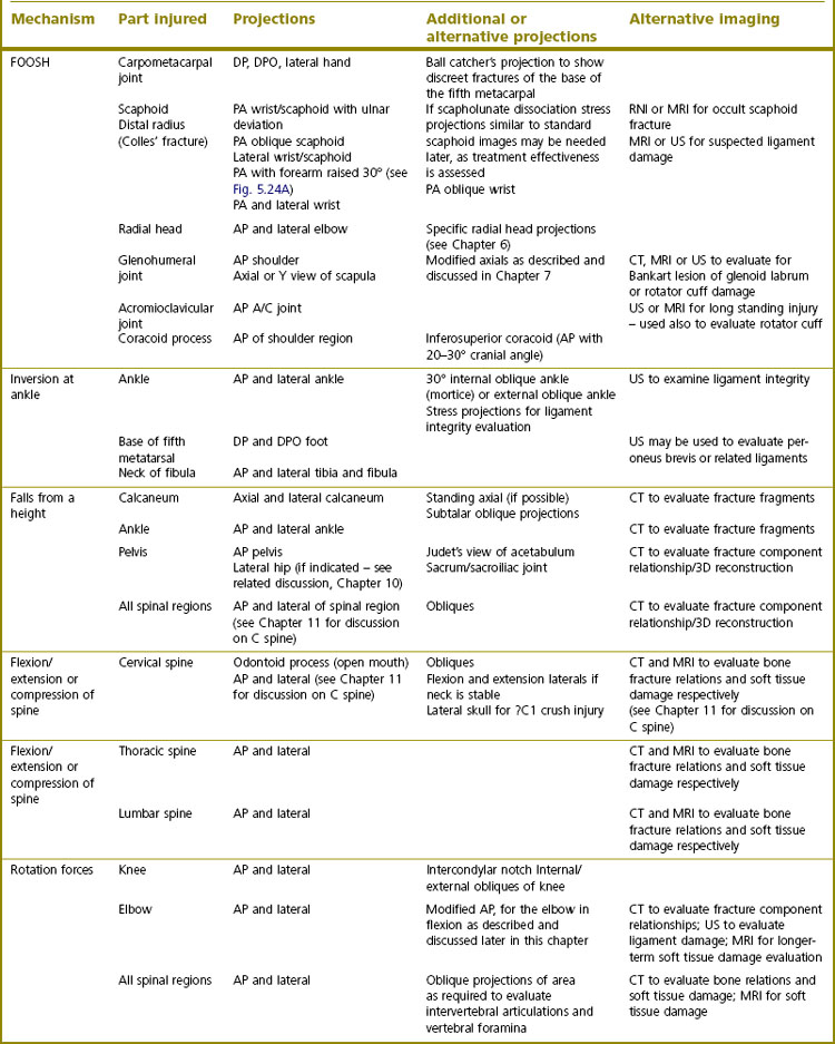
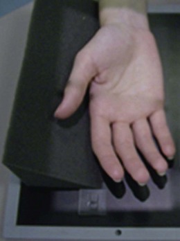
Lewis13 identified a way to address the perceived problems of the inadequacy of hand projections by suggesting that the dorsipalmar (DP) projection is obtained with the forearm medially rotated at the elbow so that the ulnar border of the hand is lifted from the cassette surface. A 15° radiolucent foam pad is placed under this aspect of the hand to immobilise the limb and raise the medial portion of the hand (Fig. 25.1), with the remainder of the technique used following that of the DP hand described in Chapter 5.
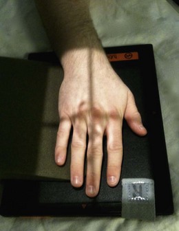
Lewis continues to make further suggestions about hand radiography that would improve visualisation of certain digits.14 Of the thumb he makes the point that, in the normal anteroposterior (AP) and lateral projections, the thenar eminence and other structures medial to the thumb are frequently superimposed over the first metacarpophalangeal joint, preventing clear visualisation owing to imperfect achievement of radiographic density. He suggests, for the AP projection, that the radiographer simply angles the central X-ray beam 10–15° along the long axis of the thumb, towards the wrist, so that the soft tissue structures are projected away from the area of interest. Using this technique helps reveal the proximal joint region without juggling with exposure factors that may overexpose the distal part of the thumb while attempting to reveal the proximal aspect (Fig. 25.2). Quite frankly, the supine AP thumb technique described in Chapter 5 is probably most suitable, especially for the patient who presents on a trolley.
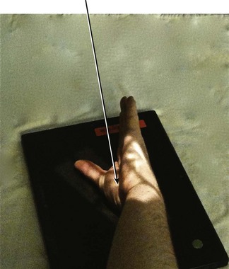
In a third suggestion about hand technique modifications Lewis describes another projection of the fifth metacarpal, a bone which is difficult to demonstrate owing to the anatomical relationship of the bones or soft tissues of the hand in the dorsipalmar oblique (DPO) or lateral projections.15 He recommends further external rotation of the hand from the lateral position by an extra 5–10° so that the overlying second to fourth metacarpals no longer superimpose. The central ray is directed towards the middle of the fifth metacarpal and angled so that the ray is parallel with the thumb, which has been extended and abducted such that it does not overlie the fifth metacarpal (Fig. 25.3). Although an elongated projection is generated, almost the whole of the fifth metacarpal becomes visible.
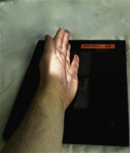
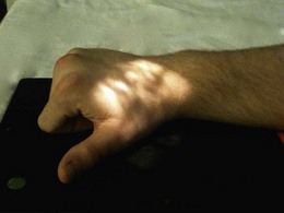
Normally used for visualising the small joints of the fingers in the arthritic patient, the ballcatcher’s16 projection may be used to show the extent of damage in the ‘fight bite’ situation (Fig. 25.4). Puncture of the assailant’s skin by the victim’s tooth may lead to the development of osteomyelitis. Other than the clinical signs of the puncture wound or soft tissue swelling, little evidence of such an injury may be noted. However, the tangential representation of the metacarpal heads generated by this projection allows the viewer to see the indentation caused when the tooth has impacted with the metacarpal during a punching injury. The technique is described in Chapter 5, but it is not necessary to expose both hands and centring must be altered to coincide with the head of the third metacarpal, collimating to the single hand.
Adapted projections of the thumb
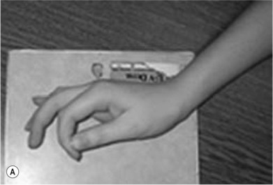
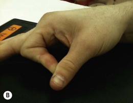
Injuries to the thumb are highly debilitating, as the ability to grip is compromised. Assessment of the integrity of the ulnar and radial collateral ligament at the metacarpophalangeal joint is achievable through the use of self-applied stressing forces in the posteroanterior (PA) thumb projection. This is achieved by using the index finger of the affected hand to generate adduction and abduction forces. The patient is asked to adduct the thumb by placing their index finger over the distal surface of the tip of the thumb and pulling it medially towards the finger; abduction is achieved by placing the tip of the index finger against the medial aspect of the tip of the thumb before pushing the tip of the thumb laterally, away from the index finger (Fig. 25.5A,B). Through stressing in a horizontal direction, the ulnar and radial collateral ligaments are strained to reveal their integrity. Rupture is revealed by widening of the respective side of the metacarpophalangeal joint that is associated with the damaged ligament.
Should a true lateral projection of the base of the first metacarpal be required to reveal subtle fractures, the Gedda–Billings projection can be used.17 Position as for the lateral thumb projection and angle the central ray 10° along the axis of the metacarpal, towards the forearm. This will free the articular surface from any superimposition over the trapezium (Fig. 25.6).
Adapted projections of the wrist and forearm
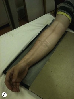
• At the commencement of positioning ensure the table is level with the shoulder
• Abduct the limb from the trunk at the shoulder, while encouraging the patient to extend their elbow so that the whole arm may be rested on the table-top
• Externally rotate the shoulder to bring the elbow joint into a true AP position as the arm is supinated
• Often when in this position the patient will naturally want to rest the arm, with the wrist very close to the lateral position; this will allow an AP elbow and lateral wrist projection to be obtained on one image. Clearly there will be crossover of the shaft of radius over the ulna
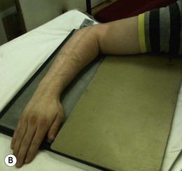
• After obtaining the previous image, the arm is internally rotated at the shoulder and the elbow flexed. The medial aspects of the upper arm and elbow are placed in contact with the table-top. The positions of radius and ulna in relation to the humerus do not alter. The forearm thus assumes a position that now generates lateral elbow and, through natural pronation of the hand, PA wrist projections. Again, there will be crossover over the radial and ulnar shafts
• For both positions described, centre to the mid forearm and collimate to include the whole of the lower forearm
Although this is not an anatomically correct approach, at least two views of the injured forearm at 90° to each other are obtained so that some approximation of the anatomical relationship can be gleaned (Fig. 25.7A,B).
Adapted projections of the elbow and humerus
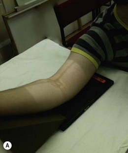
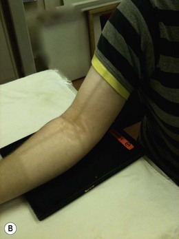
The elbow is one of the most difficult areas to examine adequately following trauma, owing to concerns about exacerbating possible neurovascular damage. Frequently the patient will present with the elbow partially flexed and will resist attempts to extend it for an AP projection because of pain. To negotiate this problem individual images of each half of the elbow joint, i.e. proximal radius and ulna or distal humerus, should be obtained. In this way a relationship between major elbow components is noted and the articular surfaces are shown to advantage.17 For AP images the posterior aspects of forearm and humeral portions of the elbow should be placed in contact with the IR in turn, thus allowing the radial and ulnar joint surfaces to be seen tangentially, or the trochlear/capitellar surfaces of the humerus to be displayed clearly, for each projection (Fig. 25.8A,B). A vertical central ray, or beam perpendicular to the joint portion of interest if a horizontal beam technique has to be used, is centred in turn at a point in the middle of the two articulation areas, i.e. over the proximal radioulnar joint for the proximal forearm and through the coronoid/olecranon fossa region for the distal humerus.
Stay updated, free articles. Join our Telegram channel

Full access? Get Clinical Tree


