1. Non-ionizing radiation
2. Noninvasive method
3. Image acquisition in any plane
4. Vessel analysis and flow quantification especially in stenotic areas in terms of peak velocity and pressure gradient
5. Ability to evaluate adjacent extravascular structures
6. Ability to acquire images without contrast administration
7. Ability to repeat acquisition, if necessary
Contrast-Enhanced MRA
In contrast-enhanced (CE) MRA, gadolinium (Gd) compounds are routinely used although, at times, other contrast agents like super paramagnetic iron oxide and chromium-labeled red blood cells can also be used. Prince et al. [20] first introduced first-pass CE-MRA in 1993. Gadolinium contrast agents, based on their pharmacological properties, result in significant T1 relaxation (shortened 10–25-fold) which results in significant signal production. Technological advancements have resulted in reliable, faster, and dynamic acquisition protocols that have significantly advanced the capabilities of MR angiography. Serial scan technique, time-resolved MRA, can be implemented that can provide a dynamic assessment of the vasculature as in DSA. This technique lessens the need for precise bolus timing and at the same time provides physiological information. In addition, time-resolved sequences allow for reduced volumes of Gd contrast for imaging. Gd compounds that are used at present are also less nephrotoxic and result in a reduced burden of hypersensitivity reactions than computed tomographic iodinated contrast media and thus are well tolerated by most patients [21–23].
Gadolinium Contrast Agents Safety Issues
Gadolinium administration has been associated with low incidence of nephrogenic systemic fibrosis (NSF). This condition following CE MRI has been observed exclusively in patients whose renal function is compromised. Grobner et al. [24] first identified this association in 2006 after which several studies confirmed this association and virtually with all types of Gd contrast agents [25–31]. NSF is a debilitating disorder resulting in fibrosis of the skin, connective tissue, and occasionally of internal organs associated with a high morbidity and mortality. As Gd compounds have been implicated in NSF, the disease entity has been thoroughly investigated and guidelines to help reduce the likelihood and impact of NSF have been proposed. Adherence to these guidelines has drastically reduced the incidence of NSF [32–34]. Current recommendations are to avoid injection of Gd contrast agents in patients with reduced glomerular filtration rate (GFR) <30 ml/min/1.73 m2. If MRA is necessary, contrast agents with predominant hepatic clearance or non-enhanced MRA should be considered.
Non-enhanced MRA
Non-Gd enhanced MRA is a viable alternative in patients whose renal functional parameters are compromised [35–37]. Blood flow can cause signal loss or gain on different types of MRA sequences. This property can be utilized to produce inherent endogenous contrast between stationary tissue and flow of blood in vessels to produce black-blood or bright-blood imaging. Black-blood imaging relies on flow-related signal loss, whereas bright-blood imaging relies on flow-related enhancement. Various MRA techniques and their major advantages and disadvantages are mentioned in Table 22.2.
Table 22.2
MRA techniques: advantages and disadvantages
MRA technique | Advantages | Disadvantages |
|---|---|---|
Contrast enhanced MRA | 1. Not flow dependent 2. Very high SNR 3. Rapid acquisition 4. Large field of acquisition | 1. Contrast administration 2. Allergies to contrast agent 3. Bolus timing issues 4. Expensive |
Non-contrast enhanced MRA | ||
A. Black-blood imaging | 1. No contrast 2. No over estimation of stenosis 3. Evaluation of vessel wall pathology 4. Evaluation of extravascular structures | 1. Under estimation of stenosis 2. Air or bone may simulate blood flow |
B. Bright-blood imaging | ||
1. Time of flight | 1. No contrast 2. Flow direction known | 1. Sensitive to patient motion 2. Signal loss in complex flow pattern 3. Tends to overestimate stenosis 4. Long acquisition times |
2. Phase contrast | 1. No contrast 2. High SNR 3. Excellent intrinsic background signal suppression 4. Directional flow and quantification | 1. Velocity related aliasing |
3. SSFP/true FISP | 1. Not dependent on flow to generate vascular contrast 2. Fast acquisition 3. Breath holding not mandatory | 1. Sensitive to motion 2. Fat appears as bright signal |
Indications of MRA Pertinent to TAVR Patients
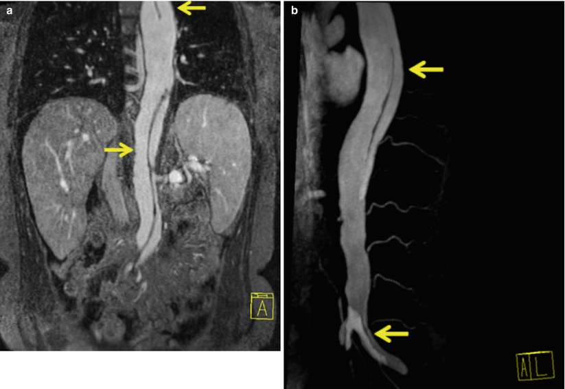
The utility of MRA as applied to TAVR patients is manifold. The indications for use include the following: to delineate relevant vascular anatomy; to identify the presence and extent of atherosclerotic disease, stenosis, thromboembolic occlusion, or any extrinsic compression over the major vessels/vascular pathways; and to identify the presence, location, and extent of vascular abnormalities (e.g., aneurysms, dissections, arteriovenous malformations, vasculitis) (Figs. 22.1, 22.2, and 22.3). For all TAVR patients, care should be taken to avoid performing MRI/MRA when contraindicated (Box 22.1).
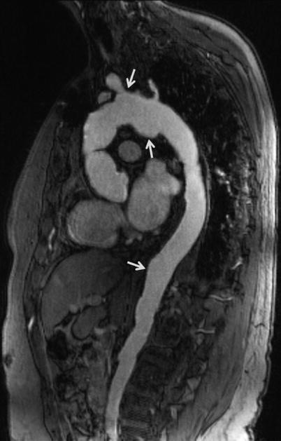
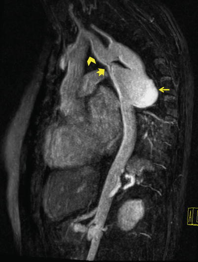

Fig. 22.1
Sagittal oblique MRA of thoracoabdominal aorta shows multiple saccular aneurysms (arrows)

Fig. 22.2
Sagittal oblique MRA of thoracoabdominal region shows coarctation of aorta (notched arrow) and a large saccular aneurysm (straight arrow) in the proximal portion of left subclavian artery. Note the steep angle narrowing/kink (chevron) in the aortic arch. Coarctation of aorta is a contraindication to transfemoral approach. Even if coarctation is not seen, navigation through steep angle of arch is difficult in this patent
An example of a MRA protocol for TAVR and the steps involved in acquiring images are listed in Table 22.3
. Baseline cardiovascular functional parameters like LVEF, end-diastolic volume, end-systolic volume, and stroke volume are calculated by acquiring SSPE cine images from base to apex either in short axis (SA) or in horizontal long axis (HLA) (4 chamber) views. These views also easily identify the presence of any thrombus or mass within the left ventricle.
Table 22.3
Cardiac MRI protocol and MRA technique
Cardiac MRI protocol |
1. Localizer scans |
2. HASTE axial and coronal slices |
3. True FISP cine vertical long axis (VLA), horizontal long axis (HLA), short axis (SA) views, and left ventricular inflow and outflow tract (LVOT) views |
4. MRA acquisition* |
5. Short axis stack of left ventricle |
6. Delayed contrast enhancement images |
7. Flow quantification across aorta and pulmonary artery |
8. Optional images (T1W, cine views across the aortic root) |
*MRA acquisition |
1. Premask images |
2. Arterial contrast MRA and time-resolved MRA |
3. Subtracted images |
4. Image post processing (MPR, MIP, VRT etc.) |
An optimal arterial MRA acquisition requires patient preparation, screening the patients for any contraindications to MRA, injection of adequate amount of contrast, and more importantly to time the study while the contrast is in transit in the arterial vessels. In doing so the protocol allows for isolation of the contrast within the arterial system. At our institution, during performance of the scan, we define the true orthogonal anatomical plane of the aortic valve from contrast-enhanced MRA images. Balanced SSFP (True FISP) cine images are acquired: few slices above, through and below the aortic valve plane. These views help in determining the number of valve leaflets, assessing the leaflets mobility, any commissural fusion or bulky mass, or vegetations on the aortic valve. This view also helps in calculating the area of stenosis. Using the same MRA source images, we also obtain a cross-sectional images of aorta and pulmonary artery (just above their respective valves). The images obtained are used to derive flow-related measurements through phase contrast (PC) angiography.
Box 22.1 Contraindications to MRI and MRA
Non-contrast |
Severely claustrophobic patient Presence of implantable stimulator devices Presence of non-compatible aneurysmal clips Presence of haemostatic surgical clips Presence of pacemaker (relative) |
Contrast |
Patient at risk of allergy to gadolinium compounds Patients known to have nephrogenic systemic fibrosis Renal compromised patients (GFR < 30 ml/min/1.73 m2) |
MRA Technique
Herein listed are the steps to acquire MRA images that we employ at our institution. First, we acquire pre-contrast MRA images or mask images. This is obtained to know the proper anatomic coverage, to plan the field of view, to identify unwanted artifacts occurring over the region of interest (ROI), and to familiarize the pattern of breath hold technique to be followed and the expected length of breath hold. Second, we acquire MRA source images and time-resolved MRA. This is followed by administration of contrast agent @ 0.1 mmol/kg body weight and saline flush of 20–30 ml. Source images are obtained in identical fashion to mask image. Usually a series of three to four MRAs can be obtained with the same or on different imaging planes over a period of time, that is, time-resolved MRA, thus providing 4D spatial and temporal vascular imaging [38, 39]. Third, we perform subtracted MRA. Subtraction of pre- and post-contrast 3D MRA data can be done to provide images without any noisy background tissue and thus improving the resolution of MRA. This method is successful only if the two data sets have identical imaging parameters and spatial orientation. Misregistration of two data sets might lead to poor image quality and artifacts. Next, we perform image post-processing. For assessing the aortic root and the aortoiliofemoral vasculature, an MRA series which shows good luminal enhancement of the vessels is selected. At our institution, we routinely use a dedicated offline 3D workstation. Workstations with similar post-processing tools are available from different vendors. 3D volumetric source or subtracted images are evaluated in multiple planes and are post processed further to highlight the ROI. Importantly, high quality source MRA images are essential to ensure accurate diagnoses as all post-processing tools rely on adequate image quality. If doubt exists or if subtracted images are not of diagnostic quality, MRA interpreting physicians should rely on the source images rather than on subtracted images.
Multiplanar Reformat (MPR)
MPR is a post-processing tool where the volumetric data is automatically arranged in three orthogonal planes, namely, axial (or transverse), coronal, and sagittal planes. MPR tool is unique as it allows image processing in any desired plane (Fig. 22.4). By toggling the imaging planes to the axis of a vessel, a profile and enface viewing plane can be obtained for assessment of vascular structures. This is especially helpful in evaluating structures that are oriented obliquely to the standard orthogonal planes. Slice thickness can be manipulated so as to visualize a large field of view albeit with slight decrease in spatial resolution. Advanced software algorithms provide curved MPR option. Curved MPR helps in laying out any curved vessel flat in a 2D plane. It can also be rotated 360° for easy assessment of vessel analysis. This is especially helpful in assessing a real versus pseudostenosis within a tortuous vessel.
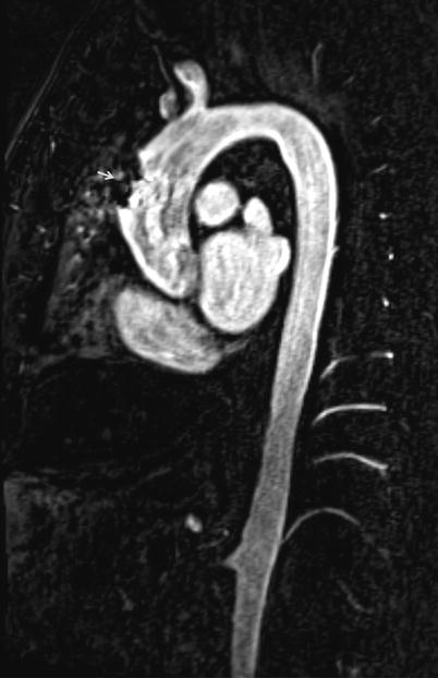

Fig. 22.4
Multiplanar reformation (MPR) of thoraco-abdominal MRA displays a large field of view of vascular structures in a single image. Dark signal metallic artifact in ascending aorta is due to previous bypass surgery
Maximum Intensity Projection (MIP)
MIP is the simplest and most widely used post-processing technique. In this algorithm, a set of parallel rays is projected on to the chosen viewing plane. The rays in their pathway take into consideration only the maximum signal intensity present in the voxel and the low intensity signals are discarded. The end result is a 3D volumetric data with brightest signal projected as a 2D image. This is useful for visualizing the entire vascular tree but with the expense of loss of depth projection (Fig. 22.5). To overcome this, MIP images are rotated in multiple imaging planes to gain an appreciation of the spatial relationship of the various structures being analyzed. The interpreting physician must be aware that any other entities with high signal intensity may also project within the plane of the vasculature and act to obscure it. This is of particular concern when images are significantly degraded by background noise. As a result, MIP imaging is more helpful when background noise has been adequately subtracted from the mask images.
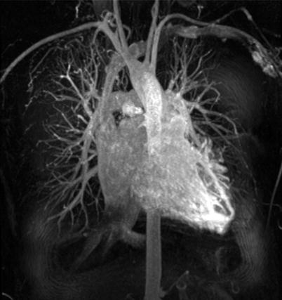

Fig. 22.5
Maximum intensity projection (MIP) of chest vasculature in coronal view shows only the brightest intensity areas and loss of depth information
Volume Rendering Technique (VRT)
VRT images allow for analyses of the voxels in the entire volume of data and provide depth information. It assigns a color based on each voxel’s signal intensity and opacity on a scale of 0–100 % (Fig. 22.6).
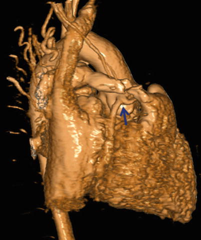

Fig. 22.6
Volume rendering technique (VRT) displays a 3D object with preservation of depth information. Note the well-visualized anomalous origin of LAD from RCA (blue arrow)
Anatomical Areas of Interest for TAVR Screening
There are a number of potential vascular and valvular pitfalls that are encountered during TAVR, and dedicated imaging may allow for greater focus during pre-procedural screening to overcome those pitfalls. These include site of access, wherein the proceduralist may encounter difficulty in puncture of the entry site (Fig. 22.7) and difficulty in passing the delivery catheter and the device due to small luminal diameter (Figs. 22.8 and 22.9), tortuous vasculature, atherosclerotic calcific disease, perforation or dissection, or thromboembolism in the aortoiliofemoral arterial segments.
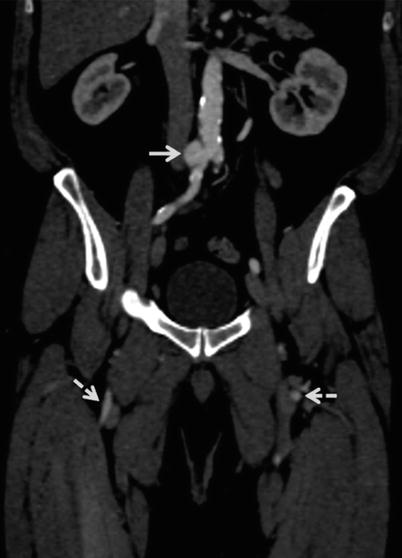
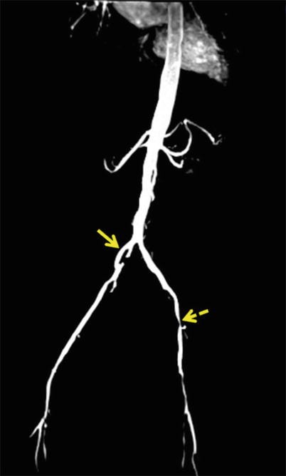
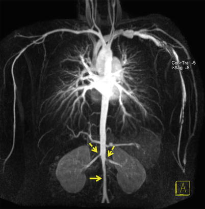

Fig. 22.7
Abdomino-pelvic coronal multiplanar reformatted (MPR) image shows saccular aneurysm (straight arrow) arising from right common iliac artery (CIA), just distal to aortic bifurcation. Nonvisualized left CIA and distal half of right CIA with reconstitution as superficial femoral arteries (dotted arrows). In this case, as the femoral arterial entry site is bilaterally blocked, alternate vascular pathways need to be considered

Fig. 22.8
Coronal maximum intensity projection (MIP) of abdominal aortoiliac arterial system. There is focal dilatation of right CIA with disrupted intimal flap within (straight arrow). Note on left side, there is diffuse narrowing of left CIA and tight stenosis of left femoral artery (dotted arrow)

Fig. 22.9
Coronal MIP of thoraco-abdominal aorta shows narrowing of the infrarenal abdominal aorta (straight arrow). It is difficult to navigate the catheter in this condition. Note also the bilateral renal artery stenosis (dotted arrows)
Further, the proceduralist may encounter unfavorable anatomy causing “device-aortic root complex” mismatch. These anatomic characteristics include low-lying coronary ostia, bulky calcified aortic leaflets, aortic root morphology that may increase the risk of aortic rupture/dissection or paravalvular aortic regurgitation (AR), and cardiac morphology that may increase the risk of cardiac perforation or tamponade.
Imaging by MRA may also aid in the decisions of valve positioning. Commonly encountered complications for which comprehensive MRA evaluation may help to avoid include low-lying device implantation resulting in impingement on the LVOT causing atrioventricular block, damage to mitral valve apparatus, high-lying device implantation, or under-expansion of the device that can lead to embolization of device. Conversely, over-expansion of device may lead to aortic rupture/dissection, cardiac perforation, or tamponade.
Aortic Root Assessment
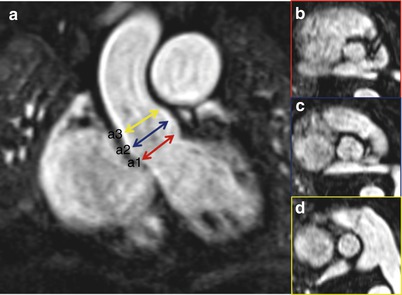
The aortic root is a complex 3D structure [43, 44]. It involves the aortic annulus, the aortic valve leaflets, and the sinotubular junction (STJ) (Fig. 22.10). The proper assessment of aortic root is the principal step for a successful TAVR procedure as it determines the device size. It is important to obtain true measurements along orthogonal planes. While assessing 3D images, reference planes should center on the ROI so that true cross-sectional (CS) plane is obtained to measure the diameter or the area for calculation. Valve sizing and positioning requires understanding the morphology of the aortic root and precise evaluation of each of above-mentioned structures.

