Artifacts
James A. Patton
The performance of routine quality assurance procedures on nuclear medicine equipment is necessary to ensure that the equipment is functioning properly prior to its use in nuclear medicine procedures. A daily routine of checking the isotope peak calibration and performing either an intrinsic flood (point source without the collimator) or an extrinsic flood (plane source with the collimator on) can identify many problems. An acceptable intrinsic flood is shown in Figure 9 A. Examples of unacceptable intrinsic flood are window off photopeak (Fig. 9 B), a photomultiplier tube not functioning (Fig. 9 C), failure of the uniformity correction circuitry (Fig. 9 D), and a broken crystal (Fig. 9 E). Performing a flood extrinsically using a plane source with the collimator in place permits an evaluation of the entire detector system in its imaging configuration and can be used to identify collimator damage that might interfere with the proper acquisition of a nuclear medicine study
(Fig. 9 F). The use of computer-based scintillation cameras permits the implementation of automated protocols to check window and peak positioning and the evaluation of uniformity correction circuitry both visually and quantitatively by calculating the value of integral uniformity in the corrected image (Fig. 9 G). When they are obtained daily, these quantitative values can be used to track trends and maintenance can be scheduled before problems become significant. Weekly monitoring of linearity and spatial resolution with a bar pattern that tests the spatial resolution of the camera (Fig. 9 H) permits the identification of problems that would otherwise go undetected.
(Fig. 9 F). The use of computer-based scintillation cameras permits the implementation of automated protocols to check window and peak positioning and the evaluation of uniformity correction circuitry both visually and quantitatively by calculating the value of integral uniformity in the corrected image (Fig. 9 G). When they are obtained daily, these quantitative values can be used to track trends and maintenance can be scheduled before problems become significant. Weekly monitoring of linearity and spatial resolution with a bar pattern that tests the spatial resolution of the camera (Fig. 9 H) permits the identification of problems that would otherwise go undetected.
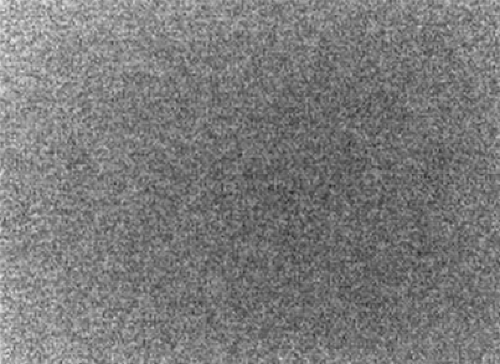 Figure 9.1 A |
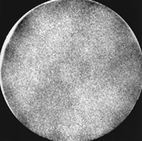 Figure 9.1 B |
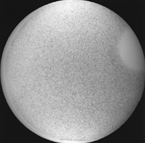 Figure 9.1 C |
 Figure 9.1 D |
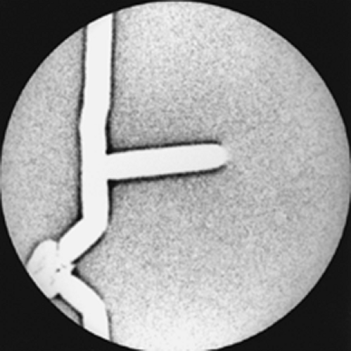 Figure 9.1 E |
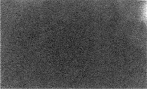 Figure 9.1 F |
The use of single photon emission computed tomography (SPECT) requires the implementation of additional quality control procedures. The center of rotation should be evaluated monthly to ensure that the center of the acquired image at every location corresponds to the center of rotation of the scanning system. Discrepancies in these values will result in circular or ring artifacts in the reconstructed images (Fig. 9 I). The use of a high-count flood for uniformity correction of the acquired planar images prior to image reconstruction is also recommended. Otherwise the presence of a nonuniformity (either hot or cold) in the response of the scintillation camera will result in the amplification of this nonuniformity into a hot or cold ring in the reconstructed images.
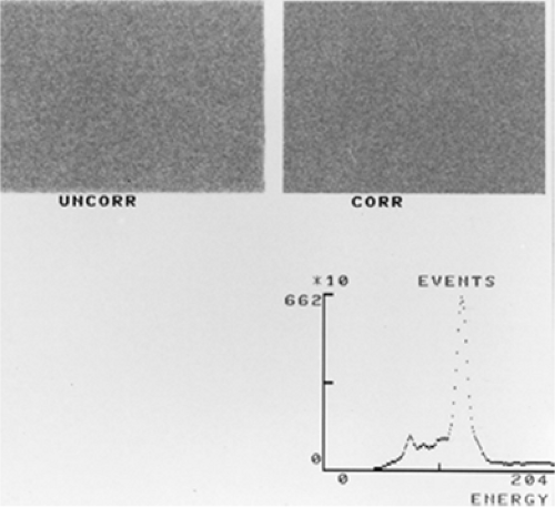 Figure 9.1 G |
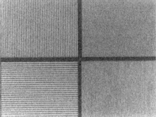 Figure 9.1 H |
However, even with the most diligent approach to routine quality assurance, there are many instances where unusual findings are noted in the images acquired in routine
nuclear medicine procedures. The following cases describe examples of these abnormalities. Some are due to improper calibration of equipment or equipment failures. Others are due to improper techniques. And finally, others are simply due to patients being studied with clinical conditions that alter the routine course of the radiotracers being used for the studies. It is the goal of this chapter to make the reader aware of the many circumstances that may produce apparent artifacts that warrant further investigation in order to identify their causes.
nuclear medicine procedures. The following cases describe examples of these abnormalities. Some are due to improper calibration of equipment or equipment failures. Others are due to improper techniques. And finally, others are simply due to patients being studied with clinical conditions that alter the routine course of the radiotracers being used for the studies. It is the goal of this chapter to make the reader aware of the many circumstances that may produce apparent artifacts that warrant further investigation in order to identify their causes.
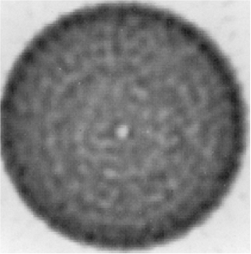 Figure 9.1 I |
Case 9.1
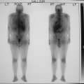
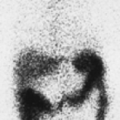
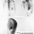
History/Procedure: A patient presented for a gastroesophageal reflux study. The study was performed with 500 μCi of 99mTc–sulfur colloid administered orally followed by dynamic acquisition of 15 sequential anterior images, each 1 minute in length, using a large field-of-view camera (Fig. 9.1).
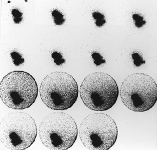 Figure 9.1 |
Artifact: Nine minutes into the study, the background suddenly increased and remained constant and nonuniform, increasing in intensity from the patient’s left to right.
Discussion: When the background suddenly changes in an image, the technologist immediately suspects an equipment malfunction. However, it is useful to first investigate the possibility of a source of high-energy photons that may have entered the vicinity of the procedure currently being performed. In this case, a patient injected with 10 mCi of 18FDG had entered an adjacent room for a stress perfusion/rest metabolism cardiac study. The shielding of the mobile camera was not sufficient to completely absorb the primary and scattered radiation resulting from the 511-keV annihilation radiation from 18F; thus the camera detected the scatter background from the cardiac patient. This is a relatively new problem in nuclear medicine owing to the recent implementation of 18FDG in laboratories that perform a majority of their studies using low-energy photon emitters. It is always important to be certain that injected patients are situated so that their presence will not interfere with ongoing procedures.
Conclusion/Diagnosis: Artifact due to interference from a high-energy source in close proximity to the scintillation camera during part of the imaging procedure.
Case 9.2
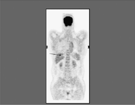
History/Procedure: A patient presented for a bone scan. The study was performed with 20 mCi of 99mTc-oxidronate (HDP) administered intravenously, followed 2 hours later by static imaging of the whole body using a rectangular field-of-view scintillation camera.
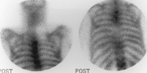 Figure 9.2 A |
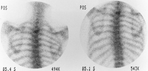 Figure 9.2 B |
Artifact: An area of decreased uptake was noted in each of the images, as demonstrated in the neck region and the spine (Fig. 9.2 A). It was noted that artifacts occurred in exactly the same area of the camera in each of the images. When the study was repeated on a different scintillation camera, the areas of decreased uptake were not seen (Fig. 9.2 B).
Discussion: When an area of decreased uptake is noted in multiple images from the same area of the camera, a photomultiplier tube/preamplifier drift or failure is immediately suspected. This problem can be easily verified by performing a flood, as shown earlier in Figure 9 C (not the same camera as used for the study described here). Usually, systems failures of this type are easily identified. However, occasionally they are very subtle and the technologists and physicians should carefully review abnormal findings of this type to be sure that they represent true abnormal uptake of the radiopharmaceutical and not equipment malfunctions.
Conclusion/Diagnosis: Artifact due to photomultiplier tube drift.
Case 9.3
History/Procedure: A patient presented for a bone scan to evaluate for metastatic disease. The patient was administered 20 mCi of 99mTc-oxidronate (HDP), and whole-body images were obtained 2 hours later using a rectangular field-of-view digital scintillation camera. Multiple areas of increased uptake were identified that were consistent with metastatic disease (Fig. 9.3 A). However, it was observed that the overall quality of the images was poor, and there appeared to have been a degradation in spatial resolution.
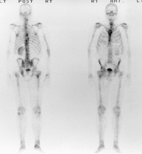 Figure 9.3 A |
Artifact: An intrinsic flood (without collimation) was performed with a 99mTc point source to evaluate peaking and uniformity before and after automated uniformity correction (Fig. 9.3 B). Both floods were very nonuniform, with an integral uniformity of 24% on the corrected flood. The automatic peaking circuitry had set the peak at 107 keV (33 keV below the actual value for 99mTc at 140 keV). This failure of the autopeaking circuitry resulted in the patient being imaged in the scatter region of 99mTc, where the camera provides a nonuniform response with a degradation in spatial resolution and contrast.
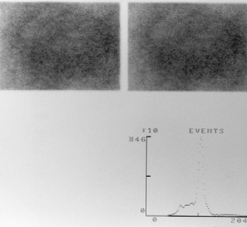 Figure 9.3 B |
Discussion: The use of digital scintillation camera technology with preset acquisition protocols and automated peaking procedures has significantly improved and simplified the procedure for performing a diagnostic nuclear medicine study. However, technologists and physicians must be alert to failure of these automated systems and be able to identify potential causes for abnormalities that may appear.
Conclusion/Diagnosis: Poor image quality because the pulse-height analyzer window was off peak.
Case 9.4
History/Procedure: A patient presented for a bone scan and was administered 20 mCi of 99mTc-oxidronate (HDP); static images of the whole body were obtained 2 hours later.
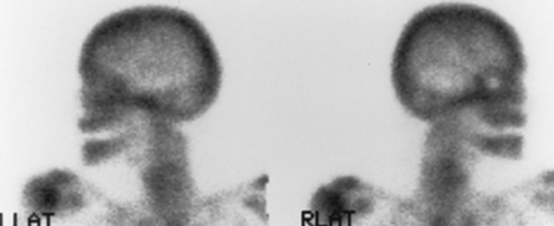 Figure 9.4 A |
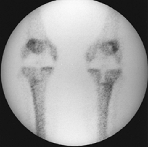 Figure 9.4 B |
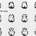
Artifact: In comparing the right and left lateral views (Fig. 9.4 A) of the head, it was noted that the patient had a “cold” area in the region of the right eye. In discussion with the patient, it was noted that the patient had an artificial right eye that was attenuating photons from the skull.
Discussion: It is known that any article of clothing that contains metal can potentially interfere with the acquisition of a nuclear medicine study. This is also true of prosthetic devices. The patient should be screened before the study for such devices, and although it may not be possible to remove them, they should be identified and labeled on the images in order to assist the nuclear medicine physicians in image interpretation. Some prosthetic devices may be very obvious, such as the bilateral knee replacements in another patient shown in Figure 9.4 B.
Conclusion/Diagnosis: Prosthetic device artifact.
Case 9.5
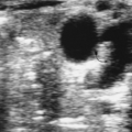
History/Procedure: A 51-year-old male presented with chronic right groin pain. The patient had a history of right total hip replacement, and the symptoms caused suspicion of infection. The patient was administered 570 μCi of 111In labeled white blood cells and images of the pelvis were acquired 24 hours postinjection (Figs. 9.5 A and 9.5 B).
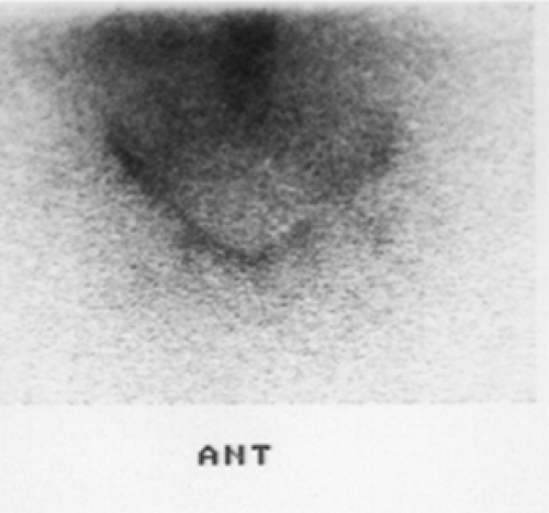 Figure 9.5 A |
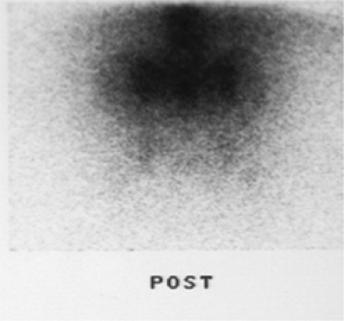 Figure 9.5 B
Related posts:Stay updated, free articles. Join our Telegram channel
Full access? Get Clinical Tree
 Get Clinical Tree app for offline access

|