Fig. 7.1
Beam-delivery systems of treatment room B of HIMAC. The horizontal beam port and vertical beam port which have a common isocenter are shown. Both beam ports have the same configuration
The method mainly used to widening the pencil carbon beam uniformly in the lateral direction is a wobbler-scattering method. The wobbler-scatterer method generates a uniform irradiation field using a combination of a wobbler magnet system and a scatterer system. The wobbler magnet system is a pair of bending magnets which are installed so that the directions of their magnetic fields are mutually orthogonal. By applying alternating currents to the two magnets which are out of phase with each other by 90°, the pencil beam delivered from the accelerator is rotated in a circular pattern as shown in Fig. 7.2b. The radius of the circle can be changed by varying the effective current supplied to the wobbler magnet system. The wobbler magnets of HIMAC beam-delivery systems are located 11.7 m upstream from the isocenter of the horizontal beam course and 9.9 m from the isocenter of the vertical beam course. Each magnet has an effective magnetic length of 660.1 mm and its pole gap is 110 mm. Both magnets can be excited at 1,200 A at the maximum.
Fig. 7.2
Uniform broad beam generated by the wobbler-scattering method. (a) A pencil beam delivered from an accelerator source, (b) a beam rotated by wobbler magnets, and (c) a beam broadened by a scattering system placed downstream from the wobbler magnet system
The annular beam is broadened by the scatterer system placed downstream from the wobbler magnet system (Fig. 7.2c). As the scatter system, a binary scatter system is often used. It has several scatterer boards and each differs in thickness from the neighbor board by a factor of two. The total thickness can be changed by selecting a binary combination of scatterer boards. The scatterer system of HIMAC contains seven metal sheets, each of which is plunged into the beam course by an actuator.
By tuning the currents to the wobbler magnets and the thickness of the scatterer it is relatively easy to make different uniform irradiation fields with different sizes. The irradiation field made by the wobbler-scatterer method is not susceptible to the variation in the beam position at the entrance of the irradiation system. Meanwhile, it has a periodic time structure corresponding to the frequency of the alternating current.
Uniform broadening of a beam in the depth direction corresponds to producing a spread-out Bragg peak (SOBP). An SOBP is formed by superposing many monoenergetic Bragg peaks. In other words, the SOBP is made to respond to the energy modulation of a monoenergetic beam. There are two main ways of modulating the beam energy and superimposing Bragg peaks: one uses a ridge filter device and the other a rotating range modulator. The ridge filter device is used for the beam-delivery system using the wobbler-scatterer method.
The ridge filter device is composed of many uniform bar-ridges, manufactured with highly precise processing technology, which are set parallel to each other on one plane as shown in Fig. 7.3. Ridge filter devices, corresponding to different SOBP widths, are often prepared for a high-energy beam and a low-energy beam. Since the cross-sectional shape for the bar-ridge determines the change of thickness, appropriate design of the bar-ridge allows delivery of a homogeneous biological dose to the target region. In the case of a carbon beam, the SOBP is composed of a range of LET components with different weighting factors at each depth. The survival rate under a mixed LET radiation field was experimentally proved to be described by a formalism proposed in the theory of dual radiation action on the basis of the linear-quadratic (LQ) model [3].
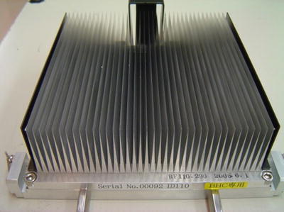
Fig. 7.3
Ridge filter
After broadening of a beam in the lateral and depth directions, the beam is cut to the shape of the target tumor projected in the beam’s eye view. A patient collimator, a multi-leaf collimator (MLC) device or their combination is used for the two-dimensional cutting of a uniform beam. The patient collimator is a block that has a tumor projection-shaped aperture. The block is thicker than the maximum range of the beam and is often made of brass, which is easy to cut by a wire-electrical discharge machine. Although the patient collimator needs to be manufactured for each irradiation direction, it reduces blurring of the lateral dose distribution because the patient collimator can be placed near the body surface of the patient.
The MLC is a device that has many pairs of thin leaves. These leaves are shifted to suitable positions to make a tumor projection-shaped aperture. Use of an MLC device has the advantages of increased speed and reduced costs for treatment preparation because no individual patient collimators need to be manufactured. In some situations the MLC device cannot be moved close to the body surface of a patient due to its size and blurring of the lateral dose; then distribution is not necessarily small.
Figure 7.4 shows the MLC used at the horizontal beam port of HIMAC beam-delivery systems. The MLC consists of 23 pairs of 6.5 mm thick iron plates with 0.25 mm spacing. The leaf with thickness of 140 mm in the beam direction has a tongue-and-groove structure except the central leaf to reduce the interleaf dose-leakage. The central leaf has the tongue structure on both sides. The leaf moves at a maximum speed of 80 mm/s and stops at a position with less than ±0.5 mm precision.
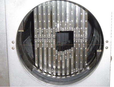
Fig. 7.4
Multi-leaf collimator (MLC)
The final step in the broad-beam method is the adjustment and conformation to the target in the depth direction using a range shifter (RSF) device and a patient compensator (bolus).
The RSF is composed of several energy absorbers having different thicknesses and the total thickness of the system can be changed by selecting suitable absorbers. The RSF of HIMAC systems consists of ten polymethyl methacrylate (PMMA) plates of various thicknesses. Combinations of plates result in thicknesses from 0.25 to 255.75 mm in a binary manner.
A patient compensator is a block that has an engraved depression in the shape of the depth direction of the target tumor volume. The block is often made of high-density polyethylene which is easy to engrave and is a low-atomic-number material for reduced scattering of the beam. Patient compensators, like patient collimators, also need to be manufactured for each irradiation direction. Figure 7.5 shows the manufacture of patient compensators by a machining center.
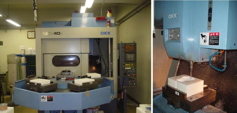
Fig. 7.5
Manufacture of patient compensators by machining center
The dose control of irradiation with the passive beam method is performed by each individual irradiation. As well as a conventional X-ray irradiation system, the treatment delivery system with carbon beams requires two independent monitor systems to ensure safe and reliable irradiation.
Each treatment delivery system of HIMAC has two identical parallel-plate ionization chambers (IC; aperture diameter about 20 cm). They are filled with atmospheric air and operated by applying +2,000 V. Each IC consists of three cathodes and two anodes that are staggered with the gap of 5 mm. There used to be other monitors, an ionization chamber and a secondary emission monitor (SEM), to have redundancy by using different types of monitors. They were, however, replaced with the present ICs after the high reliability of ICs in practical use was confirmed [3]. One of the ICs works as the main monitor and the other works as the auxiliary monitor. A beam shutter is interlocked to the beam monitors and is closed when the measured dose value reaches the prescribed value. The auxiliary monitor also closes the beam shutter when the measured dose value reaches the value that is larger than the prescribed value by 5 %.
7.1.3 Layer-Stacking Method
In the broad-beam method, with arrange modulator, a constant SOBP over the field area results in an undesirable dose to the normal tissue proximal to the target [3, 4]). Therefore, in order to avoid unwanted doses, a layer-stacking method was developed. The layer-stacking method is a way of stacking many mini SOBPs along the depth direction and changing apertures of the MLC as if drawing the lineation of the cross-sectional surface of the target tumor volume as shown in Fig. 7.6.
Fig. 7.6
Layer-stacking method. (a) Because the broad-beam method makes the fixed SOBP irradiation field, the high-dose region exists outside the tumor target. (b) The layer-stacking method can change SOBP according to the shape of the target and reduce the high-dose region outside the tumor target
At HIMAC the layer-stacking method has been used for carbon-ion radiotherapy (C-ion RT) since 2005. A thin-layer irradiation field with a mini SOBP (about 10 mm) is longitudinally swept step by step with changing thickness of a range shifter from the distal end of the target volume to the shallowest end. The mini SOBP is produced with a thin ridge filter. At each step, the radiation field shaped by the MLC changes to conform the contour of the target at each slice. Once the described dose is delivered to the slice volume, beam extraction is quickly cut off and the MLC and the range shifter are set to the next slice, and this sequence is repeated to the last slice. To accomplish the irradiation in clinically acceptable time, quick responses of the MLC motion, of the range shifter motion, and of the beam on/off are essential. Figure 7.7 shows an example of dose distributions of tissues during treatment planning. The left one is of tissues by the ordinary broad-beam method, and the right one by the layer-stacking method. The dose to the normal tissue proximal to the target is remarkably reduced by the layer-stacking method. Among the merits of this method are not only the improved dose distributions, but also that they are achieved with the same devices as the passive treatment delivery system.
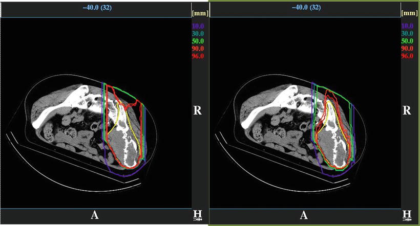
Fig. 7.7
Example of dose distribution planed to the tumor in the bone and soft tissue region by the broad-beam method (left) and the layer-stacking method (right)
Related posts:
Stay updated, free articles. Join our Telegram channel

Full access? Get Clinical Tree


