Fig. 11.1
Scene of planning CT for a patient in rolled treatment position with optical respiratory gating
11.2.3 ROI Delineation
Anatomical determination of target volumes and organs at risk is a critical oncologic task and the resultant regions of interest (ROI) are used to design and evaluate a plan. Because contrast agents cannot be used for planning CT to secure correct interpretation of the CT number, ROI delineation is often difficult. Contrast-enhanced X-ray CT and magnetic resonance imaging (MRI) may give high-contrast image of patient anatomy. Positron emission tomography (PET) gives metabolic image of tumor as shown in clinical examples in this book. These imaging modalities are thus useful for identification of gross tumor volume (GTV) on the planning CT image, for which advancement of image-processing technologies has enabled computerized image registration and fused display even in the presence of body deformation.
To plan a beam for a tumor, a radiation oncologist first defines a clinical target volume (CTV) that includes the GTV and surrounding region of clinical margin for potential infiltration. The CTV is the volume to be treated in the planning CT. However, there are always differences between planning CT and treatment times due to physiological changes, organ motion, patient setup error, beam model error, etc. All these uncertainties must be considered at the time of planning. To treat the CTV with prescribed dose in reality, appropriate margins need to be added for a planning target volume (PTV), which is intended to receive the prescribed tumor dose in treatment planning. However, it is generally difficult to quantify these uncertainties. In the cases where the dominant uncertainties are expected in the clinical margins, the setup and internal margins may be disregarded. In such cases, the PTV may be defined as identical to the CTV.
Ideally, the margin against all uncertainties should be included in the PTV. Margin for setup error should expand the PTV in lateral direction while that for range error should expand the PTV in depth direction for each field. However, in common practice, the PTV is defined before the beams are set up, which makes it difficult to define field-specific PTV. Therefore, a common practice is to assign only minimum isotropic margin for PTV to account for the setup uncertainty, which is usually smaller than the range uncertainty. Therefore, the excess of the range uncertainty is usually considered by additional depth margin to cover the PTV with an SOBP of each beam.
11.2.4 Patient Modeling
As water is the reference material in radiation dosimetry, patients are modeled volumetrically as water of variable effective density (ED) to design beams and to calculate dose distributions. Precise beam-range control to cover the tumor site with SOBP is the essence of C-ion RT. For this purpose, the ED is defined by the stopping-power ratio of the tissue to water for carbon ions. In the planning CT, the CT number ideally represents the X-ray attenuation ratio of the body tissue to water. The conversion from CT number to ED is based on strong systematic correlation between X-ray attenuation and carbon-ion stopping power for human tissues as shown in Fig. 11.2. The CT-ED relation depends on tube voltage, X-ray filter, and hardening effects. Therefore, precise calibration of the conversion curve is necessary for each CT-scanning condition. The hardening effect is object-dependent and therefore considered to be dominant uncertainty for the conversion based on measurement with calibration phantom. Because the conversion uncertainty is generally assumed to be of the order of 1 %, the precision of conversion curves in the same calibration condition should naturally be below 1 %. As there are no available tissue-equivalent materials that are valid for carbon-ion beams, the construction of the CT-ED relationship requires knowledge of the X-ray energy spectrum and elemental composition of tissues, with which X-ray attenuation coefficient or CT number and stopping-power ratio or ED of body tissues can be associated.
Fig. 11.2
Radiological properties of the body tissues in an example stoichiometric calibration; (a) and (c) are the correlation between linear attenuation coefficient ratio μ and relative electron density ρ e, (b) and (d) correlation between μ and stopping-power ratio ρ S and (e) and (f) residual histograms of ρ e and ρ S, respectively, with respect to the fitting polylines [1]
In addition to energy loss of carbon ions, which is the major source of radiation dose, multiple Coulomb scattering and nuclear interactions also influence the dose distribution. The majority of body tissues are nearly equivalent to water, which is abundant in oxygen, while bone tissues are abundant in calcium and adipose tissues are abundant in carbon. These compositional differences are ignored in the ED-based patient model. Generally, this approximation may cause only marginal effects to dose distributions in clinical cases.
11.2.5 Plan Review
In general, common tools for treatment planning, such as isodose contours on a CT image and dose-volume histograms (DVHs), are useful also for C-ion RT, where the dose refers to the RBE-weighted dose for clinical evaluation.
For a treatment in multiple positions, one cannot simply sum individual dose distributions on different CT images using rigid image-registration techniques because the patient is usually deformed in different positions. Instead, deformable image-registration techniques may have to be used. Otherwise, for clinical dose evaluation purposes, a virtual plan is made for a virtual treatment machine that delivers equivalently oriented beams in one of the positions. The virtual plan may be useful for clinical review to assess the planned treatment of the patient.
During the review of treatment plans, uncertainties in the treatment planning and delivery process should be considered. The uncertainty in the dose distribution due to patient setup or range calculation may be assessed by calculating dose distributions for the hypothetic cases that include intentional perturbations for patient position and target depth by their estimated uncertainties. This procedure is often referred to as assessment of robustness.
In the scheme where the clinical RBE is an unambiguously formulated definition rather than estimation, no uncertainty is given to the RBE. In other words, the RBE-weighted dose is the basis of prescription as the most relevant quantity to clinical endpoints. Incidentally, the true RBE may be only derived from results of clinical studies. However, direct estimation of the RBE between carbon-ion and the reference X-ray radiations is often impossible due to differences of their standard treatment protocols in fractionation scheme.
11.3 Treatment Planning for Broad-Beam Delivery
11.3.1 Library of Standard Beams
In general, an ion beam should form a field of SOBP that covers a given target volume. In practice, the treatment planning and delivery systems have a common library of standard beams to cover a variety of possible target volumes in diameter, thickness, and depth. In the case of NIRS, there are a few energies, a few field diameters, and many different SOBP in steps of typically 1 cm. For each combination of the energy, the field diameter, and the SOBP, up to several different wobbling conditions are needed to achieve sufficiently uniform field with varied range shifter thickness for possible target depths. For each of these field-formation conditions, the beam properties such as field size, SOBP, range, and physical and clinical depth-dose curves are registered as the standard beams. There are as many as several hundred standard beams at NIRS that need to be defined and registered in the treatment planning system.
11.3.2 Field Customization
The broadened beam has to be collimated to conform to the projected target contour with an appropriate lateral margin to secure sufficiently high dose (normally 95 % of a prescribed dose) to a PTV. As the field is defined as the 50 % fluence contour, distance between 50 and 95 % may be a nominal lateral margin, which approximately coincides with the penumbra width (20–80 %).
There are several different beam-collimation devices whose setting parameters need to be determined in treatment planning. Jaw-type collimators are primarily for radiation-protection purposes and thus normally set to the minimum opening that does not affect the treatment field. A multileaf collimator is a cost- and labor-effective method for collimation. Alternatively, a patient collimator is placed close to the patient to obtain sharp lateral penumbra.
The most significant advantage of carbon-ion beams is the capability of beam-range control within the field. A range shifter is set to reduce the beam range to the maximum depth of the PTV with a depth margin that accounts for additional range uncertainty. A range compensator absorbs the excess of the beam range in the field so that the distal end of the SOBP coincides with the distal end of the PTV with the depth margin. Normally, the range compensation is designed with a simple ray-tracing calculation of the water-equivalent depth. Figure 11.3 shows the principle for range compensator design and ridge-filter selection, where w 1 and w 2 are proximal and distal water-equivalent depths of a target. The thickness of the range compensator should be the difference to the maximum of w 2. The ridge filter should have an SOBP larger than the maximum of w 2−w 1.
In the conventional carbon-ion beam delivery, a ridge filter is used to form an SOBP to cover the PTV. However, since the SOBP has a fixed SOBP width, the SOBP in the proximal side cannot be conformal to the PTV. Therefore, the treated volume is normally conformal to the PTV by overlapping multiple fields.
In the layer-stacking delivery, a multileaf collimator field is dynamically conformed to the target in a layer-by-layer manner, which brings improved sparing to the organ at risk (OAR) proximal to the target, typically skin. Figure 11.4 shows an example of dose-distribution difference between the conventional and layer-stacking beams.
Fig. 11.4
Dose distributions of (a) layer-stacking and (b) conventional beams for osteosarcoma in pelvis (yellow contour) [3]
11.3.3 Dose Calculation Algorithms
Because the carbon-ion receives little scattering, the broad-beam algorithm is a reasonable approximation, in which variation of beam scattering effects are ignored and only common penumbra effects on the periphery of the field are simulated. This is simple and fast algorithm but lacks accuracy for highly heterogeneous systems. The pencil-beam algorithm models the field as comprised of two-dimensionally arranged pencil beams, which can reproduce realistic beam blurring of the field. Figure 11.5 shows an example of comparison between the two algorithms, where the broad-beam algorithm caused unrealistically sharp distal falloff except for the field penumbra region. Such artifacts due to algorithmic limitations must be carefully considered in dose-distribution analysis.
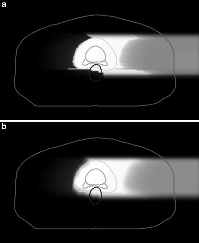
Fig. 11.5
Clinical dose distributions in grayscale from a carbon-ion beam for prostate treatment calculated with the (a) broad-beam and (b) pencil-beam algorithms [4]
11.4 Treatment Planning for Scanning-Beam Delivery
Related posts:
Stay updated, free articles. Join our Telegram channel

Full access? Get Clinical Tree


