Outline
Each chapter in this workbook will begin with a brief general Topic point of interest. Diagnostic imaging topics are an important aspect of gynecology and urogynecology and are presented throughout the book in no specific order. No questions are asked of the Learner, but the information may be helpful in subsequent cases.
Topic 1, Figure 1
- 1.
Fig. 1 . Topic: Semantics in the context of pelvic imaging

Fig. 1
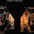
If a transducer is placed in the vagina, the exam is commonly referred to as “transvaginal” when, in fact, it is “endovaginal” or from within. We will use the term “endocavitary,” “endovaginal,” or “endorectal” in our case discussions. In this workbook, when referring to the placement of the transducer, the prefix “trans” implies “through” a structure, whereas the prefix “endo” implies “from within” a structure. The term “transperineal” is appropriate to use for an exam because the transducer is placed at the perineum through which sound waves are propagated to assess the pelvic floor structures.
Semantics in the context of pelvic imaging matters to the patient. In this workbook, the term “transducer” is used as opposed to the term “probe” for instrumentation description. Furthermore, the term “transducer” is also used for the ultrasound examination instrument when discussing findings to our patients, as well as in our reporting. When a patient hears the examiner talk about the exam “probe,” for example, during an anal sphincter complex exam, it is our contention that what they hear is, “I’m going to probe your rectum now.”
We recognize that the manufacturing vendors making the transducer may call the housing unit the “probe” and the source component that produces the ultrasound the “transducer,” but we will, nevertheless, use the term “transducer” throughout this workbook and not the term “probe.”
Case 1, Figures 2 and 3
- 2.
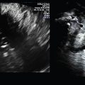
Figs. 2 and 3 are endovaginal (EV) images of a 2D midline (ML) sagittal uterus and a transverse mid-uterus. The directional relationship of the EV transducer to the patient’s perineum on the screen is consistent, but can be consistent, but can be confusing to the learner, especially in the presence of pathology. To the learner it seems logical that if the transducer is placed on the thyroid, for example, the transducer would be at the top of the screen and the anterior aspect of the thyroid would be under the transducer on the image. If the transabdominal transducer is placed at the anterior pelvis on an anteverted uterus, for example, the transducer would be at the top of the screen and the anterior aspect of the uterus would be under the transducer on the screen.

Fig. 2

Fig. 3
This may not be so apparent when pathology is found on a gynecologic EV ultrasound exam or when performing transperineal pelvic floor imaging. In the United States, the standard is that wherever the transducer is, the anatomy under the transducer is placed at the top of the screen. In other countries, the standard may be reversed. Since the transducer is in the vagina, it is located inferior relative to the patient’s body. So, if the transducer is in the vagina and the patient were to stand upright, the transducer would be angled toward the floor, which is inferior to HER BODY, but the transducer would still be at the top of the screen.
Additionally, the standard for the left side of the screen on the EV sagittal plane is anterior and the right side is posterior. For the transverse plane, when the transducer is turned 90 degrees to the patient’s right side by standard (left on the examiner’s hand), the patient’s right side is on the left side of the image, as if one is looking up the anatomy from her feet toward her head.
This assumes the examiner is holding the transducer correctly. All transducers have a notch on the top of the handle, so by touching that aspect of the transducer with the gloved hand before placing the transducer, the examiner will see the moving fingertip on the screen location before placement. If, for example, you are in a transverse plane and you angle to the patient’s right side, what is right will come into view. This becomes second nature in endovaginal imaging but is important to do correctly. Otherwise, in the presence of pathology, location of findings may be completely backward.
- a.
In Figs. 2 and 3 , in what direction on the patient is the top of the screen for both planes (sagittal and transverse)? _____
- b.
In what position is the uterus—anteverted, neutral, or retroverted? _____
- c.
Is the uterus anteflexed, retroflexed, or neither? _____
- a.
Case 2, Figures 4 and 5
- 3.
Figs. 4 and 5 are labeled with correct directional locations. To what aspect of the uterus in each plane is the gold arrow pointing—anterior or posterior?

Fig. 4

Case 3, Figures 6–10
- 4.
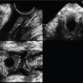
Fig. 6 is a transperineal 3D volume set of a normal urethra. When a volume is made, it is easy to forget that much more anatomic information is available to assess than what is seen on the screen. The 3D rendered image (screen bottom right) can be removed, as in this case. Image A (see red arrow) is always the original sweep plane and, in this case, is a midsagittal plane. If only a 2D midline sagittal image was done, it would look exactly the same as the A plane image.

Fig. 6
The degree of sweep, which is determined by the examiner, was made with an arbitrary 75-degree sweep angle to capture the entire adjacent lateral anatomy.
The sweep speed (also determined by the examiner) was set at the slowest option to maximize the resolution. Contrarily, if the sweep speed is set too high, the image resolution will decrease.
Look at the small dot on all three images. That dot, called the center reference point (CRP), or, alternatively, the axis center point, is the center of the anatomic sweep volume and can be moved on any plane by the examiner or post exam at a workstation. When it is moved on one plane cutting through the anatomic volume, it will move on all three planes in that same direction; therefore, one can parallel shift through the entire volume in any plane.
Note that the white dot on the A plane is at the anterior aspect of the mid-urethra (yellow arrow). Figs. 7 and 8 demonstrate slices through the original A plane in orthogonal B and C planes; therefore, the B plane is coronal to the urethral A plane at that dot (yellow line, as if you are looking anteriorly from behind the urethra) and the C plane is axial to the urethral cut through the A plane at that dot (faint blue, as if you are looking from one side to the other on the A plane). Sometimes, planes get confusing. It is always a good idea to distinguish any cut as a plane relative to the body versus the specific anatomy. It feels redundant to spend so much time on this at first when it is normal anatomy, but it pays off when there is pathology.
- a.
On the A plane, at what direction on the patient’s body is the top of the screen? _____
- b.
On the B plane, at what direction on the patient’s body is the top of the screen? _____
- c.
On the C plane, at what direction on the patient’s body is the bottom of the screen? _____
- d.
On the A plane, at what direction on the patient’s body is the bottom of the screen? _____
- e.
On the B plane, at what direction on the patient’s body is the bottom of the screen? _____
- f.
On the A plane, at what direction on the patient’s body is the left of the screen? _____
- g.
On the B plane, at what direction on the patient’s body is the left of the screen? _____

Fig. 7

Fig. 8
- a.
- 5.
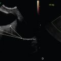
Transperineal 3D imaging greatly enhances mesh placement confidence, and manipulation of the 3D volume set can confirm and augment 2D pelvic floor findings. Fig. 9 goes back to the original 3D volume sweep. With the top of the screen as inferior, the red lines are placed at distal (screen top), mid and proximal aspects of the urethra.

Fig. 9
The mid-urethra is the ideal location for mesh placement. Visualization of the mesh on the A plane is seen as a hyperechoic focus posterior to the mid-urethra (yellow arrow), as if the mesh is coming at you, so it is seen on end; therefore, the C plane, created by the cut at the CRP dot on the A plane will show the side-to-side axial mid-urethra image behind which is the mesh. Why do we not see any mesh on the B plane? Fig. 10 demonstrates how the C plane can be pulled out of the volume set and rotated on the Z-axis to better present the midlevel suburethral mesh.

Fig. 10
Case 4, Figure 11
- 6.
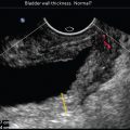
Fig. 11 is an EV midsagittal image of a nulliparous uterus. The patient’s last menstrual period (LMP) was 6 days ago. In what direction on the patient should the transducer handle be directed to see the entire uterine fundus? _____

Fig. 11
- 7.
The endometrium demonstrates several subtle thin layers on the midsagittal plane which can demonstrate anatomic changes in appearance throughout the endometrial cycle. At what phase of the cycle is the endometrium—proliferative or secretory? _____
- 8.
To what is the letter “d” pointing? _____
- 9.
In every image, there is a focal zone displayed by a carrot mark or a line of range along the side of the caliper markings where a convergence of the transducer’s lines of sight is located. The focal zone is moved throughout the exam to the area of interest so that the image is most focused there. Is the focal zone (green arrow) placed at the most optimal level to assess the endometrium? _____
Case 5, Figure 12
- 10.
Fig. 12 . In what position is this midsagittal image of a uterus? _____

Fig. 12
- 11.
What segment of the uterus is the “A” location? _____
- 12.
In what direction on the patient is the “B” location? _____
- 13.
In what direction on the patient is the “C” location? _____
- 14.
In what direction on the patient is the “D” location? _____
- 15.
In what direction on the patient is the “E” location? _____
- 16.
In what direction on the patient should the transducer be moved to better see the posterior cul-de-sac free fluid (*)? _____
- 17.
At what phase of the cycle is the endometrium? _____
Case 6, Figures 13 and 14
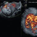
- 18.
Figs. 13 and 14 demonstrate a 3D volume set of a uterus with a sagittal original sweep acquisition (A) plane. Note the center reference points on the three orthogonal planes. Another important tool to specify areas of interest is the dotted green line of reference (LOR). The LOR, which is operator dependent, is moved on the A and B planes to any level within the volume; in this case, it is just above the endometrium to 3D render the endometrium in Fig. 14 .