Outline
Topic 3, Figure 80
- 1.
Fig. 80 . Topic: Approach to Exam Assessment

Fig. 80
How does one assess an ultrasound examination in order to thoroughly interpret the findings and create the report? Always start with global descriptions and then progress to specific details. Check caliper scales, depth of image views, relative anatomy, and echo patterns. Obtain parameter measurements. When pathology is present, describe size, contour, and altered echo pattern. Include how pathology affects the absorption of sound with description of evidence of enhanced through transmission or posterior acoustic shadowing. Use Doppler to assess vascularization. Include Doppler spectral waveform indices when patterns are altered. Perform at least two resistive indices (RI) at hypervascularized area of interest.
Case 36, Figures 81-83
- 2.
Figs. 81 and 82 are schematic drawings of the midsagittal pelvis. Figs. 81 and 82 demonstrate anteverted (AV) and retroverted (RV) uterus positions, respectively, each without and with a full bladder. The blue arrows in both the figures represent the transducer location on the anterior abdominopelvic wall just above the symphysis to assess the transabdominal pelvic view relative to the uterus. The varied positions of the uterus, however, influence the effectiveness of image quality with this approach. To optimally image the uterus when performing a transabdominal exam, the transducer should be perpendicular to the anatomy of interest; therefore, the bladder must be filled to retrovert the uterus and orient the sound-absorbing small bowel superiorly.

Fig. 81

Fig. 82
By filling the bladder, an acoustic “window” is created ( Fig. 81 , screen right) through which the sound travels with little absorption to visualize the uterus behind it. When the bladder is full, the position of the AV uterus is now RV enough that the transducer will be closer to perpendicular to the central endometrial lining which will improve the image resolution. Partially filling the bladder will enhance the image only minimally and pathology can be missed. Remember that three out of four women have an AV uterus making it the most common examiner experience. Either have the patient drink more water and wait to do the transabdominal exam or perform the endovaginal (EV) portion of the exam while the bladder is filling if you must still get the overall pelvis portion of the exam.
When the bladder is full, the RV uterus may not change in its position at all ( Fig. 82 , screen right). Steeply orienting the transducer to visualize the central endometrial lining perpendicularly will likely remain suboptimal. The examiner could move the abdominal transducer toward the patient’s head and then angle caudally (gold arrows) to try to approach the endometrium perpendicularly through the full bladder, although with varying degrees of success; therefore, the RV uterus is often substandard in transabdominal imaging, regardless of how much more the bladder is filled.
- 3.
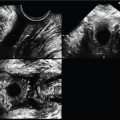
Fig. 83 (A–D) demonstrates four examples of the midline sagittal image of the AV uterus.
- a.
Which images are made with EV transducers? _____
- b.
Is the bladder full enough to assess the entire uterus of image A? _____
- c.
On which image of Fig. 83 is the cervical canal interface as well seen as the endometrial canal on the same image? _____
- d.
Which images demonstrate the endometrium well enough to identify the phase of the endometrial cycle? _____

Fig. 83
- a.
Case 37, Figures 84 and 85
- 4.
Fig. 84 . Unfortunately, patients often feel discomfort when vaginal ultrasound examinations are performed. When the transducer is placed “straight” into the pelvic floor anatomy from the introitus (green line), it will bump against the uterus and bladder. Purposeful placement and angulation of the endovaginal (EV) transducer to align with the anatomy seen on the monitor is crucial to identify and assess predictable as well as altered pelvic anatomy.

Fig. 84
Remember, the vagina extends posteriorly relative to the horizontal table on which the patient is lying, so the transducer needs to be angled down (towards the patient’s back) as it is placed into the vaginal canal. Watch the screen. You can follow yourself towards the anatomy of interest. As related to the anatomy of Fig. 84 , how would the transducer have to be moved to bring the following into view?
- a.
Uterine fundus _____
- b.
Bladder _____
- c.
Urethra _____
- d.
Rectum _____
- a.
- 5.
Fig. 85 depicts EV images of a (A) RV uterus and (B) an AV uterus. Any view of anatomy can be strengthened by directing the sound towards it; for example, in what direction would the transducer have to be directed to better see the lower uterine segment for each image?
- a.
Image A _____
- b.
Image B _____
- c.
In what phase of the menstrual cycle is the uterus in image A? _____
- d.
In what phase of the menstrual cycle is the uterus in image B? _____

Fig. 85
- a.
Case 38, Figure 86
- 6.
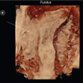
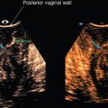
Fig. 86 demonstrates a transperineal 3D volume set of the pelvic floor using a 5–9 MHz endovaginal transducer. The acquisition sweep is a sagittal A plane (screen top left). Remember, the B plane (screen top right) is perpendicular to the A plane along the red line and the C plane (screen bottom left) is coronal to the A plane along the blue line. The volume sweep angle is arbitrarily set at 75 degrees. The small faintly colored yellow, red, and blue center reference points are at the intersection of all three orthogonal planes (A, B, C) at which is located a complex lesion at the posterior vaginal wall . The rendered image is not shown.
- a.
What does the lesion measure (calipers are at A and B planes)? _____
- b.
How would you describe the measured lesion (best seen on B plane) in terms of shape—oval, trapezoidal, round, rectangular, or serpiginous)? _____
- c.
Is it hyperechoic, isoechoic, or hypoechoic relative to the distal anterior vagina (at red)? _____

Fig. 86
- a.
- 7.
How would you describe the measured lesion in terms of location relative to the urethra and bladder? (A plane; screen top left)
- a.
Is it anterior or posterior to the mid-urethra? _____
- b.
Is it anterior, posterior, inferior, or superior to the bladder? _____
- a.
- 8.
As the A plane is sagittal on the patient , what are the B and C planes? _____
- 9.
In which of the three orthogonal planes is the urethra not seen? _____
- 10.
The screen bottom right image of Fig. 86 is the C plane rotated upright, which may seem more intuitive to see the anatomy. The rendered image is not present. Note that the green arrows demonstrate an additional round lesion along the right lateral vaginal wall that is well circumscribed, but hyperechoic to the vagina. It also demonstrates diffuse punctate echogenic foci; therefore, there are two vaginal lesions. Using the calipers along the side of the A plane, what does the second lesion measure? _____
- 11.
Which of the following is your sonographic diagnosis of the two lesions?
- a.
Urethral diverticulum
- b.
Vaginal cyst
- c.
Rectocele
- d.
Vaginal myomata
- a.
Case 39, Figures 87 and 88
- 12.
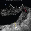
Fig. 87 is a 2D transperineal image using a 5–9 MHz transducer placed halfway into the vagina and angled slightly anteriorly to view the nearly empty bladder of a 58-year-old woman with urinary incontinence.

Fig. 87
Which of the following would best describe the bladder wall?
- a.
The wall is diffusely thickened and irregular.
- b.
The wall is thickened and smooth.
- c.
The wall is irregular and of normal thickness.
- d.
The wall is smooth and of normal thickness.
- a.
- 13.
Fig. 88 is a transperineal 3D volume set of the bladder (same patient), including the 3D rendered image (screen bottom right) using a 5–9 MHz endovaginal transducer. It is evident on all three planes that the bladder wall irregularity is diffuse. The center reference point has been brought to the irregular bladder wall. The examiner can improve the initial 3D rendered image by bringing down the (green) line of reference from the initial top of the screen into the area of interest which is at the partially filled bladder on A and B planes. Subsequently, the rendered image well depicts the bladder wall as diffusely trabeculated.

Fig. 88
Case 40, Figure 89
Note that Fig. 89 (another patient) differs from the volume set of Fig. 90 . The center reference point (CRP) of the volume set for Fig. 89 is seen in the center of the volume, which is the initial location once a sweep is done, not at the wall. In this case, it happens to be placed in the idle middle of what structure? _____

Fig. 89

Fig. 90
Additionally, the line of reference (LOR) remains higher than the concerning posterior luminal wall; therefore, the 3D rendered image (bottom right) appears more “far away” and less sharp. This is a subtle example of how bringing the CRP and LOR down to the anatomy of interest enhances the rendered image. The examiner can optimize the volume set by moving the CRP and LOR to the area of interest. This can also be done post exam at the ultrasound system or a workstation, but only if the volume is saved.
Case 41, Figures 90–93
- 14.
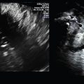
A 24-year-old woman presented to her gynecologist after gradual swelling and, now, with severe pain in her right labium. Figs. 90–93 are images of the labia using a 5–9 MHz endovaginal transducer placed at each labium. Fig. 90 is of the normal left labium in sagittal and transverse planes. The measurement was taken for relative comparison with the swollen labium, which is seen in Fig. 92 , where the calipers along the B plane right side can be used to measure on the screen.
- a.
What does the right labium measure? _____
- b.
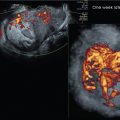
Fig. 91 does not have the calipers along the side because the image is zoomed around the centered labium, removing the calipers; so, a post-exam measurement could not be taken on this image and instead could be measured on the 3D volume set of Fig. 92 . The purpose of Fig. 92 is to demonstrate Color Power Doppler, which was initiated to assess vascular flow of the abnormal right side. Note that the pre-programmed initial Gyn pre-settings of Color Power Doppler create the appearance of practically no flow on the image.
Considering the amount of pain that the patient is experiencing, an error in the depiction of vascularity with a paucity of right labial Color Power Doppler should be considered with this appearance. Additionally, with the amount of unilateral swelling present, it is crucial to remember that the ultrasound system’s pre-established pulse repetition frequency (PRF) Gyn pre-settings may be set too high. To demonstrate actual flow of this area, the PRF should be reduced. By reducing the PRF, Fig. 92 demonstrates a much more realistic rendering of the right labium’s overall vascularity, especially of the 3D rendered image at the bottom right. Fig. 93 demonstrates the difference between the preset Color Power Doppler pickup and the correctly adjusted markedly increased flow.
Does the corrected Color Power Doppler vascular pattern appearance of the right labium suggest focal or diffuse hypervascularity? _____
- a.