Clinical Radiation Generators
4.1. Kilovoltage Units
Up to about 1950, most of the external beam radiotherapy was carried out with x-rays generated at voltages up to 300 kVp. Subsequent development of higher-energy machines and the increasing popularity of the cobalt-60 units in the 1950s and the 1960s resulted in a gradual demise of the conventional kilovoltage machines. However, these machines have not completely disappeared. Even in the present era of the megavoltage beams, there is still some use for the lower-energy beams, especially in the treatment of superficial skin lesions.
In Chapter 3, we discussed in general the principle and operation of an x-ray generator. In this chapter, we will consider in particular the salient features of the therapy machines.
On the basis of beam quality and their use, the x-ray therapy in the kilovoltage range has been divided into subcategories (1,2). The following ranges are more in accordance with the National Council on Radiation Protection (2).
A. Grenz-ray Therapy
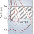
The term grenz-ray therapy is used to describe treatment with beams of very soft (low-energy) x-rays produced at potentials below 20 kV. Because of the very low depth of penetration (Fig. 4.1, line a), such radiations are no longer used in radiation therapy.
B. Contact Therapy
A contact therapy or endocavitary machine operates at potentials of 40 to 50 kV and facilitates irradiation of accessible lesions at very short source (focal spot) to surface distances (SSD). The machine operates typically at a tube current of 2 mA. Applicators available with such machines can provide an SSD of 2.0 cm or less. A filter of 0.5- to 1.0-mm-thick aluminum is usually interposed in the beam to absorb the very soft component of the energy spectrum.
Because of very short SSD and low voltage, the contact therapy beam produces a very rapidly decreasing depth dose1 in tissue. For that reason, if the beam is incident on a patient, the skin surface is maximally irradiated but the underlying tissues are spared to an increasing degree with depth. The dose versus depth curve or simply the depth dose curve of a typical contact therapy beam is shown in Figure 4.1, line b. It is readily seen that this quality of radiation is useful for tumors not deeper than 1 to 2 mm. The beam is almost completely absorbed with 2 cm of soft tissue. Endocavitary x-ray machines have been used in the treatment of superficial rectal cancers.
C. Superficial Therapy
The term superficial therapy applies to treatment with x-rays produced at potentials ranging from 50 to 150 kV. Varying thicknesses of filtration (usually 1- to 6-mm aluminum) are added to harden the beam to a desired degree. As mentioned in section 3.5, the degree of hardening or beam quality can be expressed as the half-value layer (HVL). The HVL is defined as the thickness of a specified material that, when introduced into the path of the beam, reduces the exposure rate by one half. Typical HVLs used in the superficial range are 1.0- to 8.0-mm Al.
The superficial treatments are usually given with the help of applicators or cones attachable to the diaphragm of the machine. The SSD typically ranges between 15 and 20 cm. The machine is usually operated at a tube current of 5 to 8 mA.
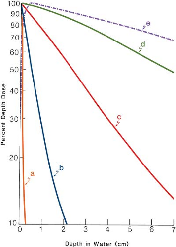 Figure 4.1. Depth dose curves in water or soft tissues for various quality beams. Line a: Grenz rays, half-value layer (HVL) = 0.04 mm Al, field diameter 33 cm, source to surface distance (SSD) = 10 cm. Line b: Contact therapy, HVL = 1.5 mm Al, field diameter = 2.0 cm, SSD = 2 cm. Line c: Superficial therapy, HVL = 3.0 mm Al, field diameter = 3.6 cm, SSD = 20 cm. Line d: Orthovoltage, HVL = 2.0 mm Cu, field size = 10 × 10 cm, SSD = 50 cm. Line e: Cobalt-60 γ rays, field size = 10 × 10 cm, SSD = 80 cm. (Plotted from data in Cohen M, Jones DEA, Green D, eds. Central axis depth dose data for use in radiotherapy. Br J Radiol. 1978[suppl 11]. The British Institute of Radiology, London, with permission.) |
As seen in Figure 4.1, line c, a superficial beam of the quality shown is useful for irradiating tumors confined to about 5-mm depth (∼90% depth dose). Beyond this depth, the dose dropoff is too severe to deliver adequate depth dose without considerable overdosing of the skin surface.
D. Orthovoltage Therapy or Deep Therapy
The term orthovoltage therapy, or deep therapy, is used to describe treatment with x-rays produced at potentials ranging from 150 to 500 kV. Most orthovoltage equipment is operated at 200 to 300 kV and 10 to 20 mA. Various filters have been designed to achieve half-value layers between 1 and 4 mm Cu. An orthovoltage machine is shown in Figure 4.2.
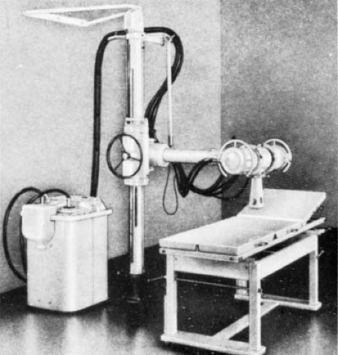 Figure 4.2. Photograph of Sieman’s Stabilapan. |
Although cones can be used to collimate the beam into a desired size, a movable diaphragm, consisting of lead plates, permits a continuously adjustable field size. The SSD is usually set at 50 cm.
Figure 4.1, line d shows a depth dose curve for a moderately filtered orthovoltage beam. Although the actual depth dose distribution would depend on many conditions such as kilovoltage, HVL, SSD, and field size, some generalizations can be made from this curve about the orthovoltage beam characteristics. The maximum dose occurs close to the skin surface, with 90% of that value occurring at a depth of about 2 cm. Thus, in a single field treatment, adequate dose cannot be delivered to a tumor beyond this depth. However, by increasing beam filtration or HVL and combining two or more beams directed at the tumor from different directions, a higher dose to deeper tumors is delivered. As will be discussed in further detail in Chapter 11, there are severe limitations to the use of orthovoltage beam in treating lesions deeper than 2 to 3 cm. The greatest limitation is the skin dose, which becomes prohibitively large when adequate doses are to be delivered to deep-seated tumors. In the early days of radiation therapy, when orthovoltage was the highest energy available, treatments were given until radiation tolerance of the skin was reached. Although methods were developed to use multiple beams and other techniques to keep the skin dose under tolerance limits, the problem of high skin dose remained an overriding concern in the orthovoltage era. With the availability of cobalt teletherapy, the skin-sparing properties of higher-energy radiation (Fig. 4.1, line e) became the major reason for the modern trend to megavoltage beams.
Although skin dose and depth dose distribution have been presented here as two examples of the limitations posed by low-energy beams, there are other properties such as increased absorbed dose in bone and increased scattering that make orthovoltage beams unsuitable for the treatment of tumors behind bone.
E. Supervoltage Therapy
X-ray therapy in the range of 500 to 1,000 kV has been designated as high-voltage therapy or supervoltage therapy. In a quest for higher-energy x-ray beams, considerable progress was made during the postwar years toward developing higher-voltage machines. The major problem at that time was insulating the high-voltage transformer. It soon became apparent that conventional transformer systems were not suitable for producing potential much above 300 kVp. However, with the rapidly advancing technology of the times, new approaches to the design of high-energy machines were found. One of these machines is the resonant transformer, in which the voltage is stepped up in a very efficient manner.
E.1. Resonant Transformer Units
Resonant transformer units have been used to generate x-rays from 300 to 2,000 kV. The schematic diagram of the apparatus is shown in Figure 4.3. In this apparatus, the secondary of the high-voltage transformer (without the iron core) is connected in parallel with capacitors distributed lengthwise inside the x-ray tube. The combination of the transformer secondary and the capacitance in parallel exhibits the phenomenon of resonance. At the resonant frequency, the oscillating potential attains very high amplitude. Thus, the peak voltage across the x-ray tube becomes very large when the transformer is tuned to resonate at the input frequency. Since the electrons attain high energies before striking the target, a transmission-type target (section 3.4) may be used to obtain the x-ray beam on the other side of the target. The electrical insulation is provided by pressurized Freon gas.
F. Megavoltage Therapy
X-ray beams of energy 1 MV or greater can be classified as megavoltage beams. Although the term strictly applies to the x-ray beams, the γ-ray beams produced by radionuclides are also commonly
included in this category if their energy is 1 MeV or greater. Examples of clinical megavoltage machines are accelerators such as the Van de Graaff generator, linear accelerator, betatron and microtron, and teletherapy γ-ray units such as cobalt-60.
included in this category if their energy is 1 MeV or greater. Examples of clinical megavoltage machines are accelerators such as the Van de Graaff generator, linear accelerator, betatron and microtron, and teletherapy γ-ray units such as cobalt-60.
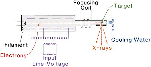 Figure 4.3. Diagram of a resonant transformer unit. |
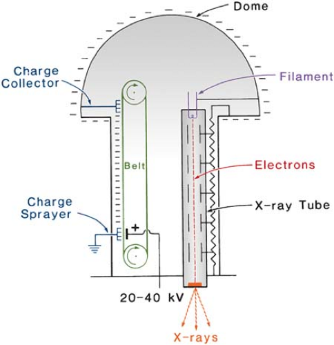 Figure 4.4. A Van de Graaff generator. |
4.2. Van De Graaff Generator
The Van de Graaff machine is an electrostatic accelerator designed to accelerate charged particles. In radiotherapy, the unit accelerates electrons to produce high-energy x-rays, typically at 2 MV.
Figure 4.4 shows a schematic diagram illustrating the basic principle of a Van de Graaff generator. In this machine, a charge voltage of 20 to 40 kV is applied across a moving belt of insulating material. A corona discharge takes place and electrons are sprayed onto the belt. These electrons are carried to the top where they are removed by a collector connected to a spherical dome. As the negative charges collect on the sphere, a high potential is developed between the sphere and the ground. This potential is applied across the x-ray tube consisting of a filament, a series of metal rings, and a target. The rings are connected to resistors to provide a uniform drop of potential from the bottom to the top. X-rays are produced when the electrons strike the target. Van de Graaff machines are capable of reaching energies up to 10 MV, limited only by size and required high-voltage insulation. Normally the insulation is provided by a mixture of nitrogen and CO2. The generator is enclosed in a steel tank and is filled with the gas mixture at a pressure of about 20 atm.
Van de Graaff and resonant transformer (section 4.1.E) units for clinical use are no longer produced commercially. The reason for their demise is the emergence of technically better machines such as cobalt-60 units and linear accelerators.
4.3. Linear Accelerator
The linear accelerator (linac) is a device that uses high-frequency electromagnetic waves to accelerate charged particles such as electrons to high energies through a linear tube. The high-energy electron beam itself can be used for treating superficial tumors, or it can be made to strike a target to produce x-rays for treating deep-seated tumors.
There are several types of linear accelerator designs, but the ones used in radiation therapy accelerate electrons either by traveling or stationary electromagnetic waves of frequency in the microwave region (∼3,000 megacycles/sec). The difference between traveling wave and stationary wave accelerators is the design of the accelerator structure. Functionally, the traveling wave structures require a terminating, or “dummy,” load to absorb the residual power at the end of the
structure, thus preventing a backward reflected wave. On the other hand, the standing wave structures provide maximum reflection of the waves at both ends of the structure so that the combination of forward and reverse traveling waves will give rise to stationary waves. In the standing wave design, the microwave power is coupled into the structure via side coupling cavities rather than through the beam aperture. Such a design tends to be more efficient than the traveling wave designs since axial, beam transport cavities, and the side cavities can be independently optimized (3). However, it is more expensive and requires installation of a circulator (or isolator) between the power source and the structure to prevent reflections from reaching the power source. For further details on this subject and linear accelerator operation, the reader is referred to Karzmark et al. (3).
structure, thus preventing a backward reflected wave. On the other hand, the standing wave structures provide maximum reflection of the waves at both ends of the structure so that the combination of forward and reverse traveling waves will give rise to stationary waves. In the standing wave design, the microwave power is coupled into the structure via side coupling cavities rather than through the beam aperture. Such a design tends to be more efficient than the traveling wave designs since axial, beam transport cavities, and the side cavities can be independently optimized (3). However, it is more expensive and requires installation of a circulator (or isolator) between the power source and the structure to prevent reflections from reaching the power source. For further details on this subject and linear accelerator operation, the reader is referred to Karzmark et al. (3).
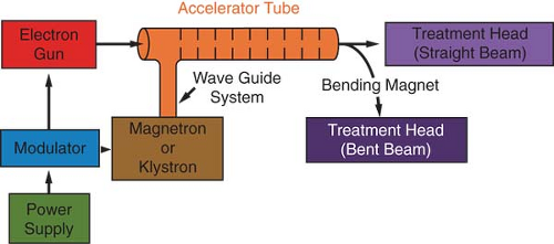 Figure 4.5. A block diagram of typical medical linear accelerator. |
Figure 4.5 is a block diagram of a medical linear accelerator showing major components and auxiliary systems. A power supply provides direct current (DC) power to the modulator, which includes the pulse-forming network and a switch tube known as hydrogen thyratron. High-voltage pulses from the modulator section are flat-topped DC pulses of a few microseconds in duration. These pulses are delivered to the magnetron or klystron2 and simultaneously to the electron gun. Pulsed microwaves produced in the magnetron or klystron are injected into the accelerator tube or structure via a waveguide system. At the proper instant electrons, produced by an electron gun, are also pulse injected into the accelerator structure.
The accelerator structure (or accelerator waveguide) consists of a copper tube with its interior divided by copper discs or diaphragms of varying aperture and spacing. This section is evacuated to a high vacuum. As the electrons are injected into the accelerator structure with an initial energy of about 50 keV, the electrons interact with the electromagnetic field of the microwaves. The electrons gain energy from the sinusoidal electric field by an acceleration process analogous to that of a surf rider.
As the high-energy electrons emerge from the exit window of the accelerator structure, they are in the form of a pencil beam of about 3 mm in diameter. In the low-energy linacs (up to 6 MV) with relatively short accelerator tubes, the electrons are allowed to proceed straight on and strike a target for x-ray production. In the higher-energy linacs, however, the accelerator structure is too long and, therefore, is placed horizontally or at an angle with respect to the horizontal. The electrons are then bent through a suitable angle (usually about 90 or 270 degrees) between the accelerator structure and the target. The precision bending of the electron beam is accomplished by the beam transport system consisting of bending magnets, focusing coils, and other components.
A. The Magnetron
The magnetron is a device that produces microwaves. It functions as a high-power oscillator, generating microwave pulses of several microseconds’ duration and with a repetition rate of several hundred pulses per second. The frequency of the microwaves within each pulse is about 3,000 MHz.
The magnetron has a cylindrical construction, having a central cathode and an outer anode with resonant cavities machined out of a solid piece of copper (Fig. 4.6). The space between the cathode and the anode is evacuated. The cathode is heated by an inner filament and the electrons are generated by thermionic emission. A static magnetic field is applied perpendicular to the plane of the cross section of the cavities and a pulsed DC electric field is applied between the cathode and the anode. The electrons emitted from the cathode are accelerated toward the anode by the action of the pulsed DC electric field. Under the simultaneous influence of the magnetic field, the electrons move in complex spirals toward the resonant cavities, radiating energy in the form of microwaves. The generated microwave pulses are led to the accelerator structure via the waveguide.
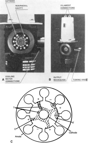 Figure 4.6. A,B: Cutaway magnetron pictures. C: Cross-sectional diagram showing principle of magnetron operation. (From Karzmark CJ, Morton RJ. A Primer on Theory and Operation of Linear Accelerators in Radiation Therapy. Rockville, MD: U.S. Department of Health and Human Services, Bureau of Radiological Health; 1981, with permission.) |
Typically, magnetrons operate at 2 MW peak power output to power low-energy linacs (6 MV or less). Although most higher-energy linacs use klystrons, accelerators of energy as high as 25 MeV have been designed to use magnetrons of about 5 MW power.
B. The Klystron
The klystron is not a generator of microwaves but rather a microwave amplifier. It needs to be driven by a low-power microwave oscillator.
Figure 4.7 shows a cross-sectional drawing of an elementary two-cavity klystron. The electrons produced by the cathode are accelerated by a negative pulse of voltage into the first cavity, called the buncher cavity, which is energized by low-power microwaves. The microwaves set up an alternating electric field across the cavity. The velocity of the electrons is altered by the action of this electric field to a varying degree by a process known as velocity modulation. Some electrons are speeded up while others are slowed down and some are unaffected. This results in bunching of electrons as the velocity-modulated beam passes through a field-free space in the drift tube.
As the electron bunches arrive at the catcher cavity (Fig. 4.7), they induce charges on the ends of the cavity and thereby generate a retarding electric field. The electrons suffer deceleration, and by the principle of conservation of energy, the kinetic energy of electrons is converted into high-power microwaves.
C. The Linac X-ray Beam
Bremsstrahlung x-rays are produced when the electrons are incident on a target of a high-Z material such as tungsten. The target is water cooled and is thick enough to absorb most of the incident electrons. As a result of bremsstrahlung-type interactions (section 3.4.A), the electron energy is
converted into a spectrum of x-ray energies with maximum energy equal to the incident electron energy. The average photon energy of the beam is approximately one third of the maximum energy.
converted into a spectrum of x-ray energies with maximum energy equal to the incident electron energy. The average photon energy of the beam is approximately one third of the maximum energy.
Related posts:
Stay updated, free articles. Join our Telegram channel

Full access? Get Clinical Tree


