Historical Perspective
The practice of medicine has been transformed by computed tomography (CT). In recognition of the importance of this technique, Cormack and Hounsfield were awarded the Nobel Prize in 1979 for their role in its development. The first clinical CT unit was placed at Atkinson Morley Hospital in England on October 1, 1971. Each image took 4 minutes to be acquired, and 2 days were needed to reconstruct the series. The clinical importance of CT was immediately appreciated; by 1976, 22 companies were manufacturing CT scanners, and in 1979, more than 1000 scanners were in use throughout the world. Since then, there has been continuous and dramatic improvement in both spatial and temporal resolution as a result of advances in both hardware and software design, particularly the development of helical and multidetector helical CT and dual-energy CT.
Creating the Computed Tomography Image
The fundamental concept of CT is to use multiple projections of an object to reconstruct the internal structure of that object. The creation of a CT image can be divided into three steps. Data acquisition involves the actual exposure to radiation (scanning of the patient) with the creation of raw data; image reconstruction involves processing of the raw data into a numerical matrix revealing the internal structure; and image display involves converting the numerical data matrix to a gray-scale image. Each of these is discussed with conventional CT, and then the changes created by the advent of helical and multidetector helical CT are described.
Data Acquisition
An x-ray tube and an opposing array of detectors as well as the associated electronics are mounted on a track or frame called a gantry. The x-ray tube produces a fan-shaped beam of x-rays that interact with the patient by absorption or scattering; some of the x-rays pass through the patient to interact with the detector array. During data acquisition, the tube and detectors rotate around the patient, and the detectors repeatedly measure the amount of x-ray energy transmitted through the patient. The amount of x-ray energy received by the detector and the gantry angle at the time of the measurement are recorded ( Fig. 65-1 ). Typically, the detector array contains 500 to 1000 detectors, each of which is sampled approximately 1000 times per revolution. Each line of this information reflects the summation of the attenuation coefficients of all structures in that x-ray path. The entire data set forms the “raw data” from which an image is reconstructed. Conventional or incremental scanning is obtained by performing a series of individual scans during suspended respiration. After each scan, the patient breathes; the table is advanced; and in most machines, the tube and detector apparatus rewinds to begin another scan.

Image Reconstruction
From the raw data, a digital image is created. A variety of techniques can be used to accomplish this; these rely on the principles of back projection, iterative formulas, or analytic formulas, either with or without Fourier transformation. The result is a matrix of numbers; in general, a 512 × 512 matrix is used in abdominopelvic CT. Each number in this matrix is called a pixel, or picture element. Each pixel corresponds to a volume of tissue or voxel within the patient; the average density of the tissue within the voxel is represented by the pixel value. The difference in attenuation of the contents of a voxel relative to water is defined as the CT attenuation number and expressed in Hounsfield units (HU).
Image Display
This digital image or number matrix is converted to a visual format for interpretation. A gray scale is used with the densest materials, such as bone (highest HU), being assigned lighter shades, whereas the least dense, such as air (most negative HU), are assigned darker shades. A problem arises in that display devices are limited to demonstrating approximately 60 shades of gray, and the human eye may distinguish as few as 30 shades; the 4096 CT numbers cannot be simply mapped without conversion. The wide range of numbers is converted for display by window width and level controls. The window level specifies the centering of the gray scale, and the choice of width specifies the numbers over which the gray scale is to extend. For example, if the window level is set to 0 and the width is set to 500, every pixel number below 250 will be black and every pixel greater than 250 will be white; if there are 50 shades of gray, each would be assigned a range of 10 numbers with the middle gray used for the numbers adjacent to 0.
Helical Computed Tomography
Helical or spiral CT involves a continuous rotation of the gantry as the patient is advanced at a steady rate through it, dispensing with the discrete steps of data acquisition in conventional CT. This continuous rotation creates a volume set of raw data that must then be segmented to create planar images. Introduced in 1989, the technology was rapidly accepted and distributed. The major advantages of helical scanning include rapid acquisition, unlimited ability to obtain overlapping images without increased radiation exposure, high-quality multiplanar reconstruction, and absence of respiratory misregistration.
Helical CT introduced several unique new concepts that the physician must understand. The first reflects the relationship between the speed of the table and the speed of the gantry. This is described as the pitch and is defined as the table feed per 360-degree tube revolution divided by the width of the collimated beam ( Fig. 65-2 ). When the patient’s movement is equal to the beam collimation, the pitch is 1. Increasing the pitch allows increased coverage in the z direction but with some increase in image noise. Use of pitches greater than 1 also decreases the radiation dose to the patient.

A second important new concept introduced by helical CT is that of reconstruction increment and overlapping reconstructions. As with conventional CT, once the scan has been obtained, the image thickness cannot be changed. However, because the data acquisition is continuous, the location of the image center along the z-axis may be altered. This has two practical applications: it allows overlapping reconstructions for use in postprocessing without any increase in radiation dose to the patients, and it reduces volume averaging effect, which may lead to improved detection of small lesions ( Fig. 65-3 ).

The demand to scan faster continued despite the dramatic improvement resulting from helical CT. This demand was met by increasing the rotational speed of the gantry and increasing the number of slices obtained with each revolution. Rotation speed has been reduced to a fraction of a second, with most high-end scanners having speeds of less than 0.5 s/rotation. Increasing the number of slices obtained per revolution was the next evolution of CT technology: multidetector helical CT (MDCT), also called multidetector-row CT and multislice CT.
Multidetector Computed Tomography
MDCT machines segment the detector array along the z-axis of the patient, allowing multiple rows of data in this plane to be obtained simultaneously. Elscint (Haifa, Israel) introduced the first MDCT machine, a dual-slice unit, in 1992. However, it was not until several manufacturers introduced four-channel machines in 1998 that the technology exploded. The technology behind MDCT is fascinating but largely beyond the scope of this chapter. Several reviews and books have been published to which the interested reader is referred. As with other improvements in CT technology, the major advantage of multiple detector rows is an increase in performance that can be used to shorten scan duration, to increase scan range, and to improve resolution. In imaging of the solid abdominal organs, radiologists have exploited both the improved resolution and speed afforded by this new technology. A significant portion of the performance gain has been used to obtain images of the organs multiple times during a single bolus of contrast material.
In discussing MDCT, it is important to distinguish between the number of channels and the number of detector rows. For example, manufacturers and radiologists often refer to 4-row or 16-row MDCT; however, this is a misnomer, and referring to 4-channel or 16-channel MDCT is more accurate. The number of data channels determines the number of data streams that can be acquired simultaneously from the detector. The number of detector rows is the number of segmented detectors in the z-axis; this number is often greater than the number of channels ( Fig. 65-4 ). However, as the number of channels increases, this discrepancy decreases.

Another important new concept must be considered with MDCT: acquisition thickness versus image thickness. Before MDCT, image thickness was an acquisition parameter. Once this was chosen and the patient was scanned, it could not be altered. However, with multidetector machines, image thickness is a reconstruction parameter; that is, one can change the image thickness after the patient has been scanned. Various reconstructed section widths are available; the number of choices varies by the manufacturer. An image cannot be created with an image width thinner than the acquisition collimation. As long as the raw data are available, additional images can be created at a different thickness.
MDCT has been used in imaging of the solid abdominal organs in several ways. There has been a reduction in slice width and scan acquisition time for routine abdomen and pelvis imaging. Scanning of a single organ, such as the liver or the pancreas, at multiple times during the rapid administration of intravenous contrast material (multiphase studies) is much easier to accomplish than on single-detector helical CT and has become part of the routine armamentarium of the radiologist. Finally, the use of very thin images during the arterial phase of injection has become helpful in CT angiography, often combined with routine images of the organ of interest.
Dual-Energy Computed Tomography
Dual-energy CT (DECT) is an emerging technology that promises to add a new dimension to CT imaging. Its utility is based on the principle that the attenuation of each element varies by the energy of the x-ray used to image it. The relationship between x-ray attenuation and x-ray energy is not linear. Rather, because of the photoelectric effect, attenuation spikes when the energy of the x-ray is at or just above the k-shell binding energy of the element. This energy level is known as the k-edge. The k-edge varies from element to element but increases with the atomic number of the element. DECT takes advantage of this phenomenon by imaging the patient at two different tube voltages. This is accomplished either by rapidly switching the tube voltage of a single x-ray tube as it rotates around the patient (rapid switching DECT) or by imaging the patient with a pair of x-ray tubes and detectors oriented at 90 degrees to each other (dual-source DECT). The lower tube voltage is most commonly 80 kVp, and the higher voltage is 140 kVp. Whereas the energy of the x-rays emitted by the x-ray tube is a spectrum of varying energies, the lower the tube voltage, the lower the average energy of the spectrum.
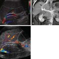
By determining the attenuation of a voxel at two different tube voltages, DECT has several potential benefits. The first is increased sensitivity to iodinated contrast media. When imaging at 80 kVp, a larger portion of the x-ray spectrum is near the k-edge of iodine (33.2 keV). Therefore, the attenuation of iodine is greater than at higher tube voltages. This increases the sensitivity of the detection of iodinated contrast media ( Fig. 65-5 ). Unfortunately, imaging at 80 kVp generates inherently noisier images than those obtained at a higher tube voltage. This disadvantage is mitigated by blending the noisy 80-kVp image with the “cleaner” 140-kVp image to create an acceptable image quality. This increased sensitivity to contrast media has been shown to increase the conspicuity of hypervascular lesions in the liver and hypovascular lesions in the pancreas.

DECT also has the ability to detect certain substances on the basis of their differing attenuation at different x-ray energies. With respect to gastrointestinal imaging, there have been investigations into use of DECT to detect and to quantify hepatic iron and fat stores. In addition, DECT has been used to detect iodine and to create iodine-only images that aid in lesion detection. Conversely, DECT has also been used to create virtual unenhanced images by removing the iodine from a single-pass contrast-enhanced DECT. These two techniques allow detection of lesion enhancement without the need for a noncontrast CT scan.
Dosimetry and Dose Reduction
There has been a significant increase in both the public and professional awareness of radiation dose in medical imaging. As CT is a procedure of relatively high dose and is used for a widening array of applications, it has received a large share of the attention. CT scanning is now the highest single contributor to human-made radiation exposure to the population. The National Radiological Protection Board in Great Britain estimated that in 1999, although only 4% of diagnostic procedures were CT scans, they contributed to 40% of overall medical radiation exposure. Unfortunately, calculating the radiation dose in CT is complex, leading to difficulty in providing simple answers to questions of dose. Important principles include the following: the dose is administered only to a certain volume of the body, not to the entire patient; the dose can vary considerably from scanner to scanner and from image to image, depending on the technical parameters set; and the percentage of the dose delivered centrally compared with the skin dose is much greater with CT than with conventional radiography.
Absorbed dose is the energy absorbed per unit mass; it is measured in the SI unit gray (Gy). Fundamental CT absorbed dose descriptors include volume CT dose index (mGy), which reflects the average radiation dose within a scan volume, and dose-length product (mGy-cm), which reflects the radiation dose over the entire scan length. One or both of these values is displayed on the operator console of newer CT machines.
The other descriptor of importance is the effective dose (mSv), which estimates biologic risk. Effective dose may be calculated by multiplying the dose-length product by a conversion factor that is based on the body part being scanned and the size of the patient. For an adult, the conversion factor for abdominal CT is 0.15. The effective dose is almost always the number a clinician or patient wants to know when they ask what the radiation dose of a CT examination is. Typical effective dose values for abdominopelvic CT scans range from 8 to 16 mSv. It is often helpful to remember that the range of background radiation in the United States is 1 to 10 mSv, with an average of about 3.6 mSv. Several excellent reviews are available for those interested in further information.
Several strategies exist to reduce radiation exposure due to CT both at the population level and during a given CT examination. Emphasis by the radiologist on performing a CT examination only to provide clinically useful information that will affect the course of treatment is the first step in reducing CT use as a population. Optimizing the study to answer the clinical question the first time avoids radiation from repeated CT studies. Limiting scan length to the area of interest also avoids excess radiation. Finally, consideration of alternative imaging modalities, such as ultrasound and magnetic resonance (MR), which do not use ionizing radiation, is also important.
In performing a given study, there are several parameters that may be adjusted to reduce the dose to the patient. The key tradeoff involved is between radiation dose and image quality. In general, parameters that reduce radiation exposure to the patient also reduce the number of photons that reach the detector. This reduced sample size increases statistical noise, which is manifested as reduced image quality. Therefore, it is important for the radiologist to understand that although the highest possible image quality is desirable, it often comes at the expense of increased radiation exposure.
Three key parameters that influence both radiation dose and image quality are the tube current-time product, tube voltage, and pitch. The tube current-time product measured in milliampere-seconds (mAs) is the product of the tube current and the time of rotation. Peak tube voltage (kVp) measured in kilovolts (kV) is the voltage applied to the x-ray tube. Decreases in current-time product result in a linearly proportional decrease in radiation dose. However, this results in an increase in image noise proportional to the inverse of the square root of the decrease in current-time product (e.g., a reduction in half of the current-time product would result in a ![]() or a 41% increase in image noise). Similarly, a decrease in tube voltage results in reduced radiation dose at the expense of increased noise and other artifacts. Finally, pitch is inversely proportional to radiation dose and directly proportional to image noise.
or a 41% increase in image noise). Similarly, a decrease in tube voltage results in reduced radiation dose at the expense of increased noise and other artifacts. Finally, pitch is inversely proportional to radiation dose and directly proportional to image noise.
Although there is no agreed on value of these parameters that will produce the optimal image, they may be adjusted to yield the lowest radiation dose possible while still achieving diagnostic image quality in a given clinical scenario. One of the most important factors to take into account is the patient’s size. Smaller pediatric patients will require a lower tube current-time product, depending on their size. Conversely, the obese adult patient will often require an increased tube current-time product and tube voltage for a diagnostic image to be obtained.
Reconstructed slice thickness is another factor that may influence radiation dose. As discussed before, with MDCT, a given CT data set may be reconstructed at varying slice thicknesses. However, for a given data set, a thinner reconstruction will have more noise than a thicker one. Conversely, given a desired level of image noise, a thinner reconstruction will require a higher dose than a thicker one.
CT scanner manufacturers have recently implemented a feature known as automated exposure control, which attempts to simplify the process of optimizing dose reduction. With automated exposure control, the operator sets an image quality parameter, the tube voltage, and the desired slice thickness. Then, as the gantry rotates around the patient, the scanner modulates the tube current such that the lowest necessary current is used to obtain the desired image quality. Determining what represents acceptable image quality may be difficult as image quality parameters vary between manufactures, and individual radiologists interpret image quality differently. However, as this technology becomes more commonplace, automated exposure control should become increasingly useful to limit radiation dose in CT.
One additional dose reduction technique on the horizon is iterative reconstruction. Iterative reconstruction is an alternative reconstruction algorithm that requires less radiation exposure than filtered back projection to generate images of similar quality. The details of this algorithm are beyond the scope of this text. However, the main limitation of iterative reconstruction is that it is a computationally intensive technique that results in long reconstruction times. Although this is an old technique that was used to reconstruct the first CT images, this limitation caused it to fall out of favor. Recent increased interest in reduction of radiation exposure combined with increasing computational processing power has renewed interest in this method. Methods that combine traditional filtered back projection with iterative reconstruction have been found to reduce radiation dose by as much as 25% to 40% while maintaining image quality and acceptable reconstruction times. Recent research reports 57% to 88% dose reduction with use of a pure form of iterative reconstruction (model-based iterative reconstruction), albeit with long reconstruction times and some loss of image quality. However, with increasing computation power and improving algorithms, iterative reconstruction holds great promise for dose reduction in CT.
Intravenous Contrast Principles
Iodine-based intravenous contrast material is routinely used in CT of the solid abdominal organs. When it is properly used, such contrast material improves lesion detection and characterization. However, when it is used improperly, contrast material can actually decrease lesion detection. In the early days of conventional CT, abdominal enhancement was described as consisting of three phases: bolus, nonequilibrium, and equilibrium. Whereas these phases are no longer as critical in protocol planning as they were with conventional CT, scanning of the liver should be completed before the equilibrium phase, which generally begins about 90 to 120 seconds after injection. This could be relevant when either patient or technical problems cause an unplanned increase in the scan delay.
With helical CT and MDCT, enhancement characteristics of abdominal structures have been more completely studied ( Fig. 65-6 ). The early arterial phase is a common name given to the period when a significant amount of contrast material is in the arterial system but little or no contrast material is in the venous system or organs. In the abdomen, this generally occurs 15 to 25 seconds after the initiation of injection in most patients. The late arterial phase describes the time when contrast material is entering hypervascular tumors and vascular organs in significant amounts; this is generally 30 to 45 seconds after the beginning of the injection. Some have termed this the portal inflow phase , as contrast material is generally seen in the portal vein also but not in the hepatic veins; however, the enhancement of the liver parenchyma in this phase is primarily due to hepatic arterial flow. Finally, the period from 50 to 80 seconds after the injection is referred to as the portal venous phase and is the time during which the liver is maximally enhanced; this delay reflects the predominant portal venous supply of the liver. Contrast material reaches the liver through the portal vein only after it traverses the mesentery and bowel. This phase has also been called the hepatic parenchymal phase and the hepatic venous phase .

Iodinated contrast material is available in varying concentrations. Sixty percent iodine concentrations (300 mg/mL) are most commonly used for abdominal applications. However, varying concentrations have been studied, with a recent trend in use of higher concentrations. One rationale for use of higher concentrations (350 to 370 mg/mL available in the United States, 400 mg/mL elsewhere) is the ability to get a greater number of iodine atoms into the organ of interest with the same injection rate. Lower injection rates may be safer and easier to use. Use of higher concentrations has been shown to improve detection of hypervascular hepatocellular carcinoma compared with preparations of 300 mg/mL.
Injection of contrast material should always be performed with a power injector. This ensures that the desired injection rates and timing are achieved. Both the rate at which the contrast material should be administered and the length of the scan delay (time from initiation of the injection of the contrast agent to time of initiation of scanning) have been studied extensively. As the rapidity of acquisition increased with helical CT and MDCT, a complete reevaluation of contrast agent administration strategies has been required. Before helical CT, the greatest concern was administration of the contrast agent to maximize the time to equilibrium phase to allow scan completion before equilibrium began. This is now easily accomplished, and the focus has been on determining the strategies to maximize visualization of various normal and pathologic structures at certain points of enhancement.
There are two additional questions to be answered with regard to intravenous administration of contrast material: the amount and method of administration. All currently used iodine-based contrast agents distribute rapidly into the extracellular space. Thus, the enhancement of vessels and organs depends not only on the dose but also on the rate of injection and the length of time from the beginning of the injection to imaging (scan delay) ( Fig. 65-7 ).

The dose of contrast material administered depends on scanner type and the specific organ of interest. Because of the various concentrations available, dose is best considered in grams of iodine. The increased speed of helical CT and MDCT has allowed dose reductions when the primary purpose of contrast is vascular opacification. However, adequate opacification of the hepatic parenchyma to optimize detection of focal lesions probably is not as dependent on speed; it has been recommended that a minimum dose of 38 g (125 mL of a 300 mg/mL formulation) should be used with helical scanning. For general parenchymal organ imaging, a dose of 120 to 150 mL of 300 to 370 mg/mL contrast material is generally used.
The volume of contrast material administered to adults undergoing CT has routinely been held constant regardless of the patient’s size. By adjustment of the dose according to the patient’s weight, a lower overall amount of contrast material may be used, creating a cost savings while maintaining image quality. A weight-based dose of 1.5 mL/kg was found acceptable in most patients for routine survey examinations.
In general, contrast material is injected at relatively high rates to obtain rapid opacification of vessels and organs and to avoid imaging during the equilibrium phase. The degree of enhancement and the time of maximum enhancement are both directly related to the injection rate. Rates for routine abdominal studies generally are 2 to 3 mL/s; this is adequate to image the abdomen during the portal venous phase of enhancement. With multiphasic imaging, a more rapid bolus helps separate the different phases; for example, with a higher rate, a greater volume of contrast material is administered to obtain a high degree of hepatic arterial enhancement in the liver before portal venous contamination begins. Rates for hepatic examinations generally range from 3 to 6 mL/s.
The scan delay is defined as the time between the initiation of injection and the initiation of image acquisition. The delay chosen depends primarily on the phase of enhancement one wishes to image. Routine abdominal studies are ideally performed during the portal venous phase; CT angiographic images are obtained during the early arterial phase and hepatic parenchymal arterial studies during the late arterial phase. The scan delay also depends on how fast the scanner is—one must consider the contrast enhancement at the end of the scan as well as at the beginning. Ideally, the scan is centered at the peak of the desired phase. Thus, with the slowest scanners, one might have to begin before the ideal opacification is reached to ensure that at the end of the scan, the enhancement phase is still appropriate; conversely, with the fastest scanners, the delay is greater to center the acquisition at the desired enhancement peak ( Fig. 65-7 ). The optimal scan delay depends on the injection rate and volume administered; when the rate is changed, the delay may require adjustment as well.
The terminology used to describe the administration of contrast material in CT varies in the literature, by local custom, and with the organ of interest. Multiphase studies are usually referred to by the number of series obtained after the injection of contrast material; for example, “biphasic” CT of the liver usually includes two contrast-enhanced scans; it may or may not include a precontrast scan. If a precontrast scan were included, some would term this a triphasic examination, whereas others would not.
As the science of contrast agent administration has progressed, patient-dependent factors have become more obvious. Most institutions use nearly the same technique for most adult patients. However, differences in cardiac output, weight, time from last meal, and fluid status affect the actual enhancement obtained on the images. In an effort to tailor the examination to the specific patient, bolus tracking systems are available that initiate scanning when the optimal enhancement has been reached. In general, these systems use a series of low-dose scans obtained at a single location within the abdomen. A region of interest cursor is placed on the aorta or liver, and a threshold density level is set. After the beginning of the contrast agent administration, scans are obtained every second or so until the density measured within the region of interest reaches a threshold value. At that time, the diagnostic scan is begun.
Another technique becoming more popular, particularly with the use of 64-channel CT machines and in CT angiography, is the use of a “saline chaser.” This was originally described with a technique of placing both the contrast agent and saline in one injector chamber, but now dual-bore (one piston for the contrast agent and one for the saline) injectors are available as well. The saline serves two functions: it increases the efficiency of the contrast agent used as no contrast material will remain in the tubing or in the peripheral circulation of the arm at the end of the injection, and it maintains high concentrations of contrast material in the circulation longer by preserving the bolus shape. This in turn has been used to decrease the total dose of contrast material administered.
Other intravenous contrast agents are being explored, primarily to image the liver with the goal of improving lesion detection and characterization. These contrast agents target either the reticuloendothelial system (Kupffer cells) or hepatocytes. However, iodine is the only intravenous agent currently used routinely in abdominopelvic CT.
Interpretation Principles
The conventional approach to CT interpretation is based on “hard-copy” film. A number of forces have changed interpretation from a film-based environment to a “soft-copy” or monitor-based environment. The number of images obtained in abdominal studies is climbing as multidetector techniques allow the creation of more (usually thinner) images. Multiple phase acquisitions and use of multiplanar reformations have led to the creation of even more images. Filming this number of images is not practical. Picture archiving and communications system (PACS) methods have helped manage these images as well as allowed enterprise-wide simultaneous visualization of images with central secure data storage.
Certain principles are the same with both film and monitor interpretation. Images should be displayed with window width and level settings appropriate for differentiation of solid-containing, fluid-containing, and air-containing structures (body window: level = 40-70, width = 380-550). Many radiologists find narrower width (liver window: level = 60-80, width = 125-150) images of the upper abdomen helpful, and viewing of these windows is suggested to aid in identification of lesions with minimal density difference from normal liver. Varieties of measurements are made to clarify findings and to include objective data in the radiology report. Regions of interest are created to obtain the average density of the contents inscribed to help lesion characterization. Size measurements on helical data sets are accurate in the axial, longitudinal, or z-axis. Bidimensional measurements are made by determining the longest single diameter, then the longest dimension that is perpendicular to the first.
Related posts:

Stay updated, free articles. Join our Telegram channel

Full access? Get Clinical Tree


