Chapter 8 Coronary Computed Tomography Angiography
INTRODUCTION
Noninvasive cardiac imaging is of vital importance for the assessment of coronary artery disease.
The currently used modalities include nuclear perfusion imaging, stress echocardiography (ECHO), magnetic resonance imaging (MRI), and most recently coronary computed tomography (CT). The latter is the only test that routinely directly visualizes the coronary arteries (with the rare exception of coronary MRI). Nuclear imaging focuses on the detection of hypoperfused myocardium downstream from coronary stenoses; however, it will miss stenoses that have developed collateral pathways and may miss triple vessel disease as a consequence of “balanced ischemia.” Stress ECHO is focused on secondary wall motion abnormalities downstream from coronary stenoses that may be present during stress only because the limited blood flow at rest may be sufficient for the lower demand of the myocardium. Cardiac MRI can image the coronary arteries directly; however, to date this has not become a routine clinical tool. However, cardiac MRI is a powerful tool to depict first pass perfusion defects and to identify viable (alive) myocardium and scar tissue, as well as infarcted or fibrosed myocardium.
Coronary computed tomography angiography (CTA) has the potential to image cardiac function, cardiac perfusion, myocardial morphology (e.g., calcification indicating remote myocardial infarct [MI]), and the coronary arteries, all in one acquisition. Therefore, coronary CTA provides a potential alternative to the established noninvasive cardiac imaging technologies.
PATIENT SELECTION
In addition to the standard contraindications to CT scanning with iodinated contrast, there are additional factors that can be considered relative contraindications for coronary CT, or predictors of poor image quality and poor evaluability of coronary CTA. These factors may depend on the exact scanner type. In general, single source scanners do not allow routine imaging of coronary arteries in patients with atrial fibrillation or high heart rates and irregular heart rhythms. Dual-source technology has faster temporal resolution, and therefore the “penalty” for scanning patients with arrhythmias (penalty = poorer image quality) is less severe, and some preliminary data suggest that atrial fibrillation should not necessarily be considered a relative contraindication with that particular scanner type. In general, coronary CTA is challenged by contrast-to-noise restrictions (relatively noisy images) and by high-radiation doses. The higher the body mass index of a patient, the more likely the study is to be not entirely diagnostic (may contain segments of coronary arteries that are nonevaluable). Another challenge for coronary CT is the presence of extensive coronary calcium. Calcium causes blooming (looks bigger than it really is), which may make it impossible to evaluate the underlying lumen for presence of stenosis. In addition, the presence of calcium aggravates motion artifact. Because coronary arteries have small diameters, there are general challenges in terms of spatial resolution. An excellent maneuver to help overcome this challenge is administration of nitroglycerine before the CTA acquisition. Nitroglycerine dilates the coronary arteries and therefore improves image quality by reduction of the effect of volume averaging artifacts and improves the contrast-to-noise ratio of smaller vessels.
Putting it all together, the ideal patient for coronary CTA is a thin person who is not pregnant, not too young (radiation issue), and not too old (prevalence of heavy calcification), with a low and steady heart rate, with normal renal function, and otherwise no contraindication to iodinated contrast material, beta-blockers, or nitroglycerine. Additionally, this patient should have an unanswered clinical question, a question that coronary CTA has the potential to answer, and a question the answer to which may affect the patients’ clinical management. Clinical indications currently considered valid for coronary CTA will be reviewed later in the chapter. Please note that currently is the most important word of the last sentence; cardiac CT is a rapidly developing field (as are many others in medicine) and much of what may be accepted as standard of care today may be considered obsolete within a decade or even sooner.
Before discussing the clinical applications of cardiac CT, the technical limitations and pitfalls of this technique must be reviewed.
TECHNICAL DEVELOPMENT OF SCANNERS
Recent developments in mechanical cardiac CT have dramatically improved the ability of CT to visualize the heart and coronary arteries. The major improvements that have made this possible are fast gantry rotation speed and image reconstruction algorithms that allow us to use only a subset of projections from one (or possibly multiple) rotation off the gantry. Generally, half a gantry rotation is necessary to acquire all projections that generate an axial image. The temporal resolution is the time it takes to collect these projections and is calculated as one-half the gantry rotation speed. Thus, if the gantry rotation speed were 330 ms (gantry spins around the patient 3 times per second), then the temporal resolution is 1/2 × 330 ms equaling 165 ms. The temporal resolution is comparable to the shutter speed of a camera; the shorter (or faster) the shutter speed is, the more likely are you to generate motion free images of a rapidly moving object. Although 165 ms represents one of the fastest temporal resolutions of current 64-slice multidetector computed tomography (MDCT) systems, it is not fast enough to obtain motion-free images of the coronary arteries in all phases of the cardiac cycle. Therefore, image reconstruction is typically performed in mid to late diastole, where there is the least cardiac motion. Additionally, beta-blockers are administered before the scanning to reduce the patient’s heart rate to 60 beats per minute or below. This results in a longer diastolic rest period, less motion of the coronary arteries, and reduces the risk of motion artifact.
If the development of cardiac CT over the past decade is reviewed, it is noted that cardiac imaging was possible with 4-slice systems, but most research studies that were conducted removed a substantial number of coronary artery segments (up to 30%) from their analysis because of nonevaluability. This was in part as a result of presence of motion artifact (image blurring). The reason for the large amount of motion artifact with these systems is the slower gantry rotation speed of approximately 500 ms (resulting in a temporal resolution of 250 ms). The major improvement with 64-slice CT systems was in the reduction of the number of nonevaluable segments, which is in keeping with the improved temporal resolution. Typical gantry rotation speeds of 16-slice scanners are 420 ms to 370 ms (even though some remained at 500 ms at first), resulting in temporal resolutions typically ranging from 210 ms to 185 ms. This has caused the number of nonevaluable coronary artery segments to go down to on average approximately 6%. Keep in mind that temporal resolution and the resulting motion artifact is only one of the two major reasons for unevaluable segments, the other one being presence of dense coronary calcium. The next major step in the development of cardiac CT was the 64-slice MDCT generation. All major vendors have offered a 64-slice MDCT system, even though the number of slices is calculated in different ways. Some vendors have actually 64 equally sized detector rows within the gantry and have x-rays emitted from one focal spot in the x-ray tube. One vendor, however, uses 32 equally spaced detectors and two focal spots on the x-ray tube that alternate in emitting x-rays. Thus they acquire two different projections for each of the 32 detector rows, resulting in 64 individual projections.
Up to 64-slice technology, all vendors were going along the same route with their technical innovations. However, from here on, there are substantial differences in the newer generation of scanners. One vendor developed a two-x-ray tube and two-detector array system, that is, a dual-source system. This allows collecting 180 degrees worth of projections in only one quarter of an actual gantry rotation. Thus the temporal resolution is one fourth the gantry rotation speed (not one half). At a gantry rotation speed of 330 ms, this system has a temporal resolution of 83 ms, currently the fastest temporal resolution available.
Two other vendors have widened their detector arrays to 256 and 320 detector rows, which cover up to 16 cm of the chest with only one rotation. This eliminates the need for gating and some arrhythmia issues; however, the temporal resolution remains lower than for dual-source CT (gantry rotation/2), and therefore motion artifact remains an issue. Another vendor is improving the axial step-and-shoot acquisition method to allow substantial reduction in radiation dose in patients with low heart rates. However, patients with higher heart rates may not benefit from this acquisition method.
TECHNICAL PRINCIPLES
There are a number of technical aspects that are substantially different for cardiac CT compared to all other CT applications. They revolve around improving temporal resolution, synchronization of data acquisition with the cardiac cycle, and minimizing radiation dose to the patients. The latter is an important issue because cardiac CT has a substantially higher radiation dose compared to nongated chest CT. This is because of the small pitch that is used. To allow an image to be reconstructed at any location in z-axis and at any phase of the cardiac cycle, redundant data have to be acquired. This is generally achieved by using a pitch as small as 0.2 to 0.3. This means that each rotation around the patient overlaps to 80% with the previous, or in other words, each section through the heart may see x-rays from up to five consecutive rotations.
Retrospective Gating versus Prospective Triggering
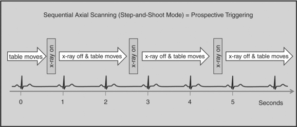
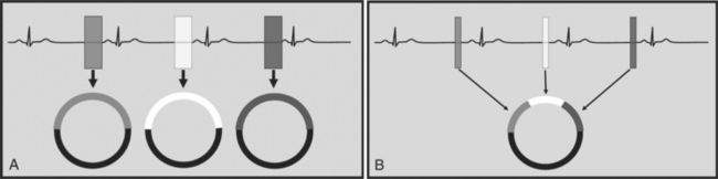
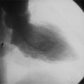
There are two general approaches to cardiac synchronization of the CT acquisition. One is prospective and “observes” the electrocardiogram (ECG) for a small number of heart beats (or more accurately the peak of the R-wave or R-peak) and then anticipates when the next R peak is to occur. Given the anticipated time point of the future R peak, the scanner will then only acquire x-ray projections in a prespecified phase of the cardiac cycle (usually late in diastole where the heart is most quiescent). This approach is called prospective triggering because the x-ray tube is triggered to shoot in a predefined cardiac phase. Data acquisition is in an axial fashion, and the table only moves in between heartbeats and is stationary during x-ray transmission. This approach has the advantage of having a low radiation dose to the patient, but it has a number of disadvantages. One of the major disadvantages is that typically only one dataset (or few similar ones) can be acquired in the anticipated cardiac cycle, which may not turn out to be of optimal image quality (Fig. 8-1).

FIGURE 8-1 Prospective triggering mode. This mode uses sequential axial (nonspiral) acquisitions during every other heart beat. X-rays are only emitted during a predefined cardiac window (typically diastole), and the tube is turned off during the reminder of the cardiac cycle. In the in-between heartbeats the table moves forward by the equivalent of the detector width (step-and-shoot mode).
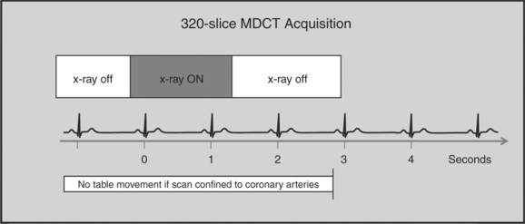
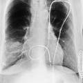
The newer 256- and 320-slice scanners use a modified step-and-shoot mode. Because their detectors cover a large volume, in many cases the entire heart, no table motion is necessary to acquire a coronary CTA dataset. Having the tube current turned on for approximately one entire heartbeat allows acquiring a dataset for analysis of cardiac anatomy and function. Theoretically, x-ray exposure can be limited to a short segment in diastole if only coronary artery visualization, and if no information on function is desired. Multi-phase reconstruction (to improve temporal resolution) would, however, require data acquisition during several consecutive cardiac phases (Fig. 8-2).

FIGURE 8-2 Whole organ coverage computed tomography. Current 320-slice scanners have a detector width of 16 cm in z-dimension, which allows acquisition of a coronary computed tomography angiography without the need to move the table. The x-ray tube is turned on only for the duration of one heartbeat. If whole chest coverage is desired, a step-and-shoot mode with only two steps is used.
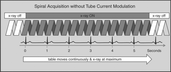
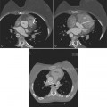
A radically different approach is retrospective gating (Fig. 8-3). Retrospective gating allows acquiring unlimited complete datasets in any phase of the cardiac cycle. This approach uses a spiral CT acquisition, in which the x-ray current remains turned on during the entire scan. The user may then in retrospect define what phase of the cardiac cycle to reconstruct. The major advantage of this approach is that the interpreter may decide to try a different phase of the cardiac cycle if the initial reconstruction demonstrates motion artifact. Another advantage is the ability to “edit” the ECG. ECG editing allows the user to select heartbeats that should not be used for reconstructions (e.g., premature ventricular contractions [PVCs]), or to correct trigger points that were not placed on an R peak by the computer algorithm. The major disadvantage of retrospective gating is the high radiation dose to the patient. For this reason a number of dose reduction strategies were developed.

FIGURE 8-3 Retrospective gating. This mode is a spiral computed tomography angiography acquisition, in which the tube emits x-rays during the entire cardiac cycles over a 5- to 20-second period (depending on z-axis coverage and scanner type). Data that were acquired during a specific cardiac phase (typically diastole) are then retrospectively selected to reconstruct the corresponding images. Any phase of the cardiac cycle (early systole to late diastole) can be reconstructed. Functional cine images can be obtained by reconstructing datasets every 10% of the cardiac cycle.
Tube Modulation
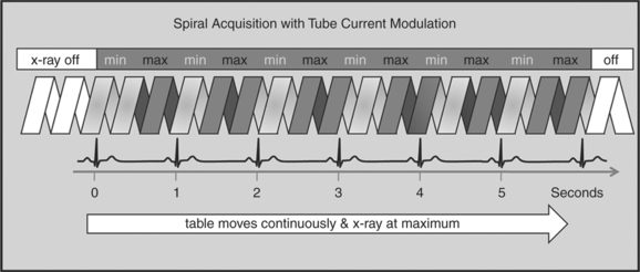
One of the most important dose reduction strategies in cardiac CT is ECG-correlated x-ray tube current modulation or short tube modulation. In this algorithm the scanner does perform a spiral acquisition using the retrospective gating method; however, it prospectively down regulates the x-ray tube current (typically in systole and usually down to approximately 20% of the maximum). This reduces the radiation dose to the patient during systole, but nevertheless allows for reconstructions of images in systole, if necessary. The penalty for reducing the tube current is a higher noise level. This approach is clearly a compromise trying to capture the advantages of both the prospective triggering and the retrospective gating acquisitions (Figure 8-4).

FIGURE 8-4 Retrospective gating with x-ray tube modulation. This mode is a variant of retrospective gating, in which the tube emits the desired amount of x-rays during diastole (or any other predefined window), but in which the tube current is substantially reduced during the remainder of the cardiac cycle. This allows optimal noise levels during diastole, but results in increased noise in systole. This technique allows reduction of the radiation dose by up to 50% if the heart rate is low.
HALF-SCAN VERSUS MULTI-SEGMENT RECONSTRUCTION
To capture images without blurring from rapid cardiac motion, it is important to achieve a high temporal resolution. Temporal resolution refers to the time it takes to collect all the data (projections) to generate an axial source image. The time it takes to collect these data (the temporal resolution) is dependent on how fast the CT gantry spins around the patient. In conventional CT, the temporal resolution is equal to the gantry rotation speed. There are, however, ways to improve the temporal resolution for cardiac CT imaging. Two algorithms can be applied, the “half-scan” reconstruction algorithm, or the “multi-segment reconstruction” algorithm (Fig. 8-5A, B).

FIGURE 8-5 Half-scan reconstructions compared to multi-segment reconstruction. A, The half-scan (partial scan or single segment) reconstruction algorithm takes advantage of the fact that only 180 degrees worth of projections are needed to generate an image. Note that 180 degrees refers to the x-ray tube position and that that results in projections covering 180 degrees plus the fan angle. This reconstruction mode results in reduction of the temporal resolution by 50% (one-half the gantry rotation speed) compared to conventional algorithms. B, The multi-segment reconstruction algorithm allows utilizations from projections that are collected from two to four subsequent heartbeats at identical cardiac phases. This assumes that the heart returns to identical coordinates during consecutive cardiac cycles. This mode allows collection of all necessary projections during a shorter time window with respect to the cardiac cycle length (improved temporal resolution), even though the overall time it takes to collect these projections is stretched over two to four heartbeats.
SCAN ACQUISITION
Beta-Blockers and Nitroglycerine
With current generation of single source scanners (64-slice, 256- or 320-slice MDCT), it is advisable to slow the heart rate by administration of beta-blockers. This can be done by oral administration, intravenous application, or a combination of both. The effect not only reduces the motion of the coronary within the image acquisition window (less motion artifacts), but it also results in a lower radiation dose if ECG based tube current modulation is used. The application of oral nitroglycerine immediately before scanning results in increased diameter of the coronary arteries and substantially improves evaluability.
Breath Holding and Positioning
It is important to practice inspiratory breath holding with the patient on the CT table before scanning. This has a number of important beneficial effects. First, the patients are familiar with the breath hold instructions and are more likely to perform optimal breath holds. Second, the physician or technologist can ensure that patients perform sufficient breath holds (long enough, no slow exhalation, etc.). Third, the heart rate varies between rest and breath holding, and the beta-blocker dosage can be adjusted to the heart rate that is seen during the breath holds.
Contrast Injection
There are a number of injection protocols that can be applied to coronary CTA. It is beyond the scope of this chapter to review all these. However, there are a number of common principles that are important to review. The intravenous catheter is ideally of large bore and placed in the right antecubital fossa. The right-sided injection is somewhat preferred because of a shorter route to the heart and because it avoids the crossing of dense contrast past the left internal mammary artery (LIMA) and the great vessels via the left innominate vein. This has the potential to cause streak artifact, which, for example, can hinder the assessment of a portion of a LIMA graft.
High flow rates (5 to 7 ml/sec) are needed for adequate opacification of the coronary arteries. Larger patients generally require faster flow rates (and larger overall volumes) to achieve the same opacification as smaller patients. Dual-head injection pumps are standard and allow a saline chaser bolus to follow the contrast injection (biphasic protocols). This allows for washing out the veins and right atrium.
Some sites prefer using triphasic protocols, in which the initial injection is contrast at a fast rate, say 5 ml/sec (phase 1), followed by a slower rate of contrast (e.g., 2 ml/sec), or a mixture of saline and contrast (phase 2), and lastly followed by pure saline (phase 3). The proposed advantage of these protocols is that they result in “better” opacification of the right ventricle, while still avoiding excessive mixing artifact. Thus, evaluation of right ventricular function and ventricular septal motion is thought to be improved. However, the value of triphasic over biphasic injection protocols has not been shown today.
Image Reconstruction (Best Phase Selection)
The initial reconstruction of images of coronary CTA datasets is usually performed in mid to late diastole in which the heart is most quiescent. Late diastole is usually less desirable because the atrial kick generates rapid motion of the coronary arteries, especially the right and left circumflex coronary artery. The field of view of the axial source slices is limited to the heart to maximize in-plane resolution (12 to 15 cm). Slice thickness is 0.6 to 1 mm, and most centers use an overlap of about one third of the slice thickness. (e.g., 0.75-mm slices with 0.5-mm spacing). Typically the images are initially analyzed for presence of coronary motion artifact, and if motion blurring is found, additional reconstructions are necessary. Late systolic reconstructions may be helpful if right coronary artery (RCA) motion cannot otherwise be eliminated by reconstructing various diastolic phases. During interpretation the interpreter may need to jump back and forth between different phases because each segment of the coronary arteries may be best displayed in different phases. In the presence of stents or calcium that makes interpretation difficult, reconstructions are repeated with sharper high-contrast kernels. Additional reconstructions of a larger field of views are performed with thicker slices for a review of extra cardiac structures.
CORONARY ANATOMY
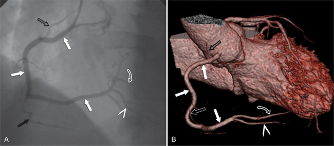
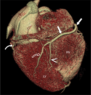
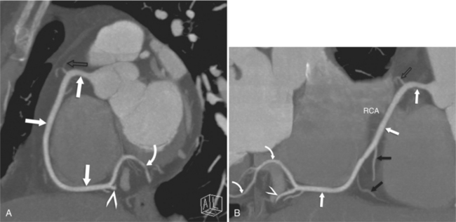
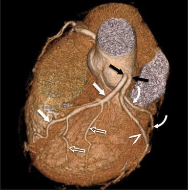
The RCA originates from the right sinus of Valsalva. The first RCA branch is the conus branch, which supplies the myocardium of the right ventricular outflow tract (RVOT). Occasionally the conus branch may have a separate ostium from the right sinus. The RCA gives rise to anterior right ventricular (RV) free wall branches and acute marginal branches that run along the angle that the anterior and inferior RV free walls form. The RCA is dominant in ≈80% of cases and runs in the right atrioventricular groove up to the crux of the heart (the point of the inferior cardiac surface where the atria and ventricles meet), where it bifurcates into a posterior descending artery (PDA) that runs within the inferior interventricular groove, and a posterior left ventricular branch (PLV) that supplies the inferior left ventricular (LV) wall (Figures 8-6, 8-7, 8-8). The PLV often gives rise to a small atrioventricular nodal branch at the crux of the heart. If the RCA is nondominant, it usually does not reach the crux of the heart, and the PDA and PLV are supplied by the left circumflex coronary artery (LCX).

FIGURE 8-6 Normal right coronary artery (RCA). A, Invasive angiogram of normal RCA (white arrows) shows conus branch (open arrow) arising from proximal RCA, acute marginal branch (solid black arrow), and bifurcation of RCA into posterior descending artery (arrowhead) and posterior left ventricular branch (open curved arrow). B, Volume-rendered reconstruction of coronary computed tomography angiography in a different patient shows normal right coronary artery (white arrow), small conus branch (black open arrow), acute marginal branch (white open arrow), posterior descending artery (arrowhead), and posterior left ventricular branch (open curved arrow).

FIGURE 8-7 Right dominant system. Inferior volume-rendered view of distal right coronary artery (arrows) shows bifurcation into posterior descending artery (arrowhead), and posterior left ventricular branch (open curved arrow), indicating a right dominant system. The distal left circumflex artery (curved arrow) is small. LV, left ventricle; RV, right ventricle.

FIGURE 8-8 Normal right coronary artery (RCA). Maximum intensity projection (MIP) and curved multiplanar reconstruction images of normal RCA. A, MIP image of the RCA is referred to as the “C-view,” because the RCA (white arrows) may frequently be visualized in its entirety and resemble the letter C. Side branches are typically only partially visualized because they leave the image plane. Note: conus branch (black open arrow), posterior descending artery (arrowhead), and posterior left ventricular branch (curved arrow). The atrioventricular node branch can be seen ascending from the cranial most portion of the PLV. B, Curved multiplanar reconstruction image of the computed tomography angiography shows a centerline reconstruction of the entire right coronary artery (arrows) but distorts all other anatomy. Note: conus branch (black open arrow), acute marginal branches (black arrows), posterior descending artery (arrowhead), and posterior left ventricular branch (curved arrows).
The left main coronary artery (LM) origin is usually more cephalad compared to the RCA ostium. The LM originates from the left sinus of Valsalva and bifurcates within 2 cm of its origin into the left anterior descending artery (LAD) and LCX (Figures 8-9, 8-10). Occasionally there is no LM, and the LAD and LCX both originate directly from the left sinus of Valsalva (Fig. 8-11). An LM trifurcation is a situation in which there is a third branch arising from the LM between the LAD and LCX (Fig. 8-12). This branch is called ramus intermedius.

FIGURE 8-9 Normal left main coronary artery (LM). A, Invasive angiogram of normal LM (black arrow) shows left anterior descending artery (white arrows) giving rise to diagonal branches and septal perforators, and nondominant left circumflex artery (curved arrows) giving rise to two large obtuse marginal branches (arrowheads). B, Volume-rendered reconstruction of coronary computed tomography angiography (different patient) shows normal left main coronary artery (black arrow), left anterior descending artery (white arrows) giving rise to two small diagonal branches (open arrow), and left circumflex artery (curved arrows) giving rise to a large proximal obtuse marginal branch (arrowheads).

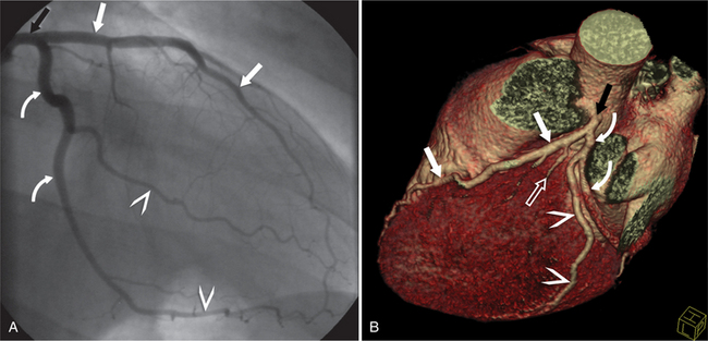
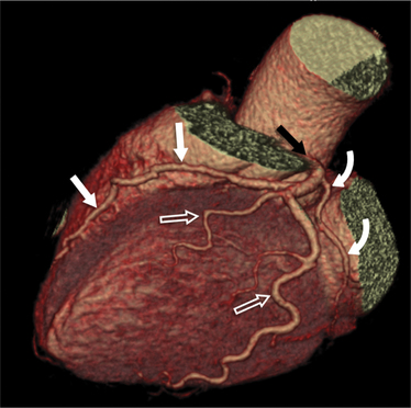
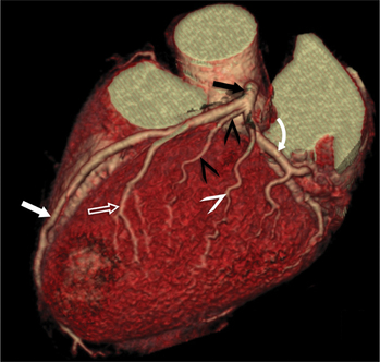
FIGURE 8-10 Normal coronary anatomy. Volume-rendered reconstruction of coronary computed tomography angiography shows the opposite end of the spectrum of normal (compared to Figure 8-9) with a large branching first diagonal branch (open white arrows) and a small left circumflex artery with no obtuse marginal branches. Note the left anterior descending artery (white arrows).

FIGURE 8-11 Absent left main coronary artery. Volume-rendered reconstruction of coronary computed tomography angiography shows a variation of normal anatomy with absence of a left main coronary artery (LM) and the left circumflex artery (LCX) and the left anterior descending artery (LAD) arising directly from the left sinus of Valsalva (black arrows). Note LAD (white arrows) with diagonal branches (open arrows) and LCX (curved arrows) with obtuse marginal branch (arrowhead).

FIGURE 8-12 Ramus intermedius. Volume-rendered reconstruction of coronary computed tomography angiography shows left main coronary artery (black arrow) trifurcating into a ramus intermedius (black arrowheads), left anterior descending artery (white arrow), and left circumflex artery (curved arrow). Note: diagonal branch (open arrow) and obtuse marginal branch (white arrowhead).

Stay updated, free articles. Join our Telegram channel

Full access? Get Clinical Tree

