Overview
The current trends in vascular imaging are to increase the reliance on noninvasive approaches, to minimize complications linked to invasive imaging, and to reserve invasive techniques for therapeutic interventions.
Arteriography, while still the gold standard for the evaluation of the arterial system, is performed with greater speed and lower complication rates than in previous decades. This has been achieved with the use of smaller catheters and decreased procedure times linked to improved digital imaging technologies.
Magnetic resonance angiography (MRA) has become more reliable as newer pulse sequences improve the quality of the magnetic resonance angiograms. MRA can be performed without intravenous contrast material or after the administration of a gadolinium contrast agent.
Computed tomographic angiography (CTA), despite being noninvasive, still relies on the intravenous administration of iodinated contrast material. Image acquisition times and image resolution have improved. The acquired image sets can be reprojected and rendered as three-dimensional (3D) datasets.
Doppler ultrasound imaging has strengths and weaknesses when compared with these other imaging modalities. This chapter reviews different aspects of these imaging approaches and compares their diagnostic efficacy.
Catheter-Based Arteriography
Arteriography remains the gold standard examination for the evaluation of patients prior to any vascular intervention. Current techniques allow for outpatient diagnostic studies to be performed with extremely low morbidity and mortality. Fully digital imaging technologies have replaced the equipment used in the 1970s and 1980s. Nonionic and low-osmolar iodine-containing contrast agents have reduced complications such as allergic reactions and postcontrast renal failure. Imaging of vascular structures is dependent on producing x-rays, opacifying the vascular structures of interest with iodinated contrast, and then recording images as the contrast agent transits through the vasculature.
Equipment and principles
Diagnostic angiography relies on the attenuation of x-rays that have entered and then exited the body. The exiting x-rays are attenuated by the amount of soft tissue traversed and their electron density. When vascular structures are filled with iodine-containing contrast agent they become much denser than the surrounding soft tissues. The amount injected must be sufficient to permit preferential visualization by the x-ray imaging device.
The penetrability of x-rays in soft tissues relates directly to the energy of the x-ray photons and is described by the kilovoltage (kV). For angiography, it is usually set between 70 and 80 kV but can be adjusted based on the amount of contrast seen on the final films. Lowering the kV will improve the contrast between objects on the film, but it will deliver more radiation to the patient. Increasing the kV increases penetration of the x-ray beam but reduces image contrast.
The x-ray tube defines the area from which x-rays are produced and the x-ray beam is further focused by collimators (lead screens that reduce the size of the beam to fit the body part being imaged as closely as possible).
A large space is required for the equipment and personnel needed to perform the procedure. The room is usually based around the x-ray tube, a patient table, and an x-ray detector. Many digital imaging systems have a C arm configuration with the x-ray tube coupled to the x-ray detector by a C-shaped bracket so that they can rotate together. The patient lies on a table situated between the tube and the detector ( Fig. 34.1 ). Imaging device configuration varies considerably in sophistication, from small portable systems to table-mounted systems equipped with moving tables for the performance of run-off arteriography.

Digital imaging
The resolution of digital images depends on the size of the imaging detector and the matrix size of the digital image. Large image fields that cover up to 16 inches need a large matrix size such as 1024 by 1024 pixels to give 1.3 line pairs per millimeter of spatial resolution.
Most units allow for single-station imaging at a fixed location over an arterial segment or venous segment. More expensive configurations with a moving table can provide multiple station bolus-chasing images for evaluation of the lower extremity run-off arteries.
Digital subtraction builds on digital imaging by obtaining one or several mask images prior to radiographic contrast agent arrival in the imaging field. The mask image is then subtracted digitally from the images with contrast to display the areas containing contrast ( Fig. 34.2 ). Patient movement during injection causes an imaging mismatch, as does respiratory excursion. Full patient cooperation remains necessary for high-quality imaging. Digital subtraction techniques reduce the amount of contrast agent needed to visualize a vessel properly.

General principles: arterial
Vascular access sites are determined by the pattern of disease. The common femoral artery is the preferred arterial access site because it is a large vessel and its use is associated with low complication rates. The axillary artery is of comparable caliber to the common femoral artery, but because the brachial plexus is intimately wrapped around it in the brachial fascia, nerve-related complications are possible (0.4% to 9.5%). Low brachial artery punctures, when performed under ultrasound guidance, are safer. Radial artery access can also be used. Direct popliteal artery punctures have an increased rate of complications and are reserved for highly specific indications. Direct puncture of vascular prosthetic grafts can be used when other access sites are not available.
General principles: venous
Lower extremity venography is performed during continuous fluoroscopic monitoring of iodinated contrast agent being injected in a pedal vein. Normally the patient is placed on a tilt-table so that gravity can help distend the veins. Full opacification of the veins is needed to exclude deep vein thrombosis. Images are acquired at the different levels of the leg.
Common femoral vein punctures are performed when the iliac veins and the inferior vena cava have to be studied. Large volumes of contrast contrast, typically 30 to 40 cc, are then rapidly injected while digital venography is performed.
Direct ultrasound guided punctures into the popliteal or tibial veins are occasionally done during venous interventions.
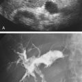
Upper extremity venography is occasionally performed to map the anatomy of the upper extremity veins ( Fig. 34.3 ). More commonly, upper extremity venography is done during an intervention, typically venous thrombolysis to treat an acute deep vein thrombosis of the upper extremity veins, or as part of dialysis access graft evaluation.

Iodinated contrast agent administration
The amount and rate of contrast agent injection during angiography depends on the size of the vessel and the amount of blood flow in the vessel segment being studied. The highest injection rates are used in the proximal ascending and descending aorta (70 to 80 cc injected at a rate of 30 to 40 cc/s). Selective studies of the mesenteric vasculature can require large volumes of iodinated contrast agent (up to between 50 and 60 cc at rates of 3 to 5 cc/s) in order to opacify both the artery branches and mesenteric veins. Lower extremity run-off studies are conducted by sequentially shifting the imaging field-of-view over the leg arteries during the injection of a bolus of 60 to 90 cc at a rate of 6 to 10 cc/s. Unilateral arterial studies of the arms and legs require 20 to 30 cc.
The general trend toward the use of nonionic and low-osmolar iodine contrast agents has been driven by the decrease in morbidity such as pain, discomfort, and allergic reactions when these iodinated contrast agents are used.
Administration of iodinated contrast material may not be appropriate when renal function is depressed. Below an estimated glomerular filtration rate (eGFR) of 30 mL/min per 1.73 m 2 , use of an iodinated contrast agent is relatively contraindicated unless the patient is on dialysis. Contrast is administered cautiously and with a hydration protocol when the eGFR is between 30 and 60 mL/min per 1.73 m 2 . There are no contraindications, except for possible allergic reactions, for eGFR above 60 mL/min per 1.73 m 2 .
Accuracy and reproducibility
The diagnostic accuracy of angiography has been verified by direct surgical correlations. It has been accepted as a gold standard. There are possible limitations in the carotid artery and peripheral arterial systems. In cases of near-occluded carotid arteries, the small amount of contrast that enters the distal internal carotid artery may not permit adequate evaluation of the diameter and quality of the artery.
In the lower extremity arteries, opacification of the peripheral run-off vessels in the leg and foot is sometimes not possible. The use of on-table arteriograms in the operative suite while the patient is under anesthesia can circumvent this problem.
Multiple projections are often needed to improve visualization of arterial lesions, a reflection of the eccentric nature of atherosclerotic lesions. Rotational arteriography is another approach to estimate more precisely the degree of stenotic narrowing in an artery.
Complications
Complications are common at the artery access site. The incidence of pseudoaneurysms and hematomas increases with increasing catheter size and shorter compression times after catheter withdrawal. Arteriovenous fistulas are more likely to occur with punctures made lower down the thigh. Complications of catheter entry such as dissections and subintimal injuries are linked to poor catheter manipulation and can occur at the access site or further along the arterial tree.
The incidence of renal failure following angiography is contested but can be as high as 10%. Allergic reactions to iodinated contrast agents are much lower than for intravenous injections yet still occur.
Recent concerns regarding radiation exposure, particularly in young or pregnant patients, also drive the preference for other less-invasive imaging modalities.
Because of these potential complications, arteriography should be used judiciously when serial examinations are contemplated.
Contraindications
Contrast allergy is a relative contraindication. In general, premedication with steroids and the selection of a different contrast material significantly decrease the risk of severe allergic reaction. Poor renal function is also a relative contraindication.
- •
Digital angiography decreases procedure times and therefore morbidity compared with arteriography as practiced with older film emulsion technology.
- •
Complications of catheter-directed arteriography at the puncture site include hematomas, pseudoaneurysms, and arteriovenous fistulas.
- •
Other complications of catheter-directed arteriography include various forms of damage to the artery wall such as dissections and embolization.
- •
Contrast arteriography is considered the gold-standard test for arterial evaluation. A requirement is that additional imaging planes should be obtained when estimating the severity of arterial stenosis.
- •
Complications such as contrast allergies and impaired renal function have decreased with the use of nonionic and low-osmolar iodine-containing contrast media.
Magnetic Resonance Angiography
MRA is a truly noninvasive modality operating on a completely different physical principle from arteriography. Diagnostic MRA preceded CTA and was previously considered the best method for noninvasive vascular imaging. CTA now competes with MRA because of its ease of use and overall better spatial resolution. MRA is mostly used for evaluating the aorta, the proximal portions of mesenteric branches, the carotid arteries, the intracranial arteries, and the run-off arteries of the legs.
There are two main forms of MRA. With time-of-flight (TOF) MRA, flowing blood is visualized when specific radiofrequency pulse sequences and magnetic field gradients are applied. Contrast-enhanced MRA (CE-MRA) requires an injection of a gadolinium complex that alters the magnetic characteristics of blood and permits visualization of blood in the vessels with the application of MRA pulse sequences. Cost and availability limit the use of MRA. Examination times are long and often more than one imaging sequence is needed for diagnosis. MRA does not perform as well as CTA when moving structures such as the pulmonary arteries are imaged or when fine detail is sought in arteries of a few millimeters or less in diameter. Newer noncontrast MRA techniques can image blood directly but have the disadvantage of relatively long acquisition times and the creation of images where both arteries and veins are visualized.
Equipment and principles
The cost of the basic equipment supersedes by many times the cost of the other technologies.
For imaging, the patient is placed into a large bore magnet operating at magnetic field strengths typically at or above 1.5 Tesla. This causes water protons to align with the magnetic field. Additional coils generate radiofrequency (RF) signals and magnetic field gradients. RF pulses are applied to the volume of tissue to be imaged and can select portions of the body through a combination of an RF pulse and synchronous application of a magnetic field gradient. The RF pulse disturbs the alignment of the water protons. As the protons realign to their resting state in the magnet, they emit characteristic RF energy. Detection and decoding of these RF signals, emitted by the tissue, create the MR image.
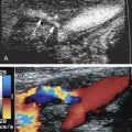
Imaging of flowing blood with MRA is performed mostly with rapid gradient echo sequences with a technique called time-of-flight (TOF) imaging. Gradient echo sequences use RF pulses of very short duration that are applied very rapidly to the same slice location. Static protons in the selected slice quickly become saturated. In two-dimensional (2D) TOF, flowing blood enters the imaging slice and the unsaturated protons give off a strong signal ( Fig. 34.4 ). Because blood is continuously being replaced by the inflow of unsaturated protons, it produces a signal and appears bright. This effect is known as flow-related enhancement ( Fig. 34.5 ) and is the basis of TOF MRA. These images are then stacked electronically and processed with a maximum intensity projection algorithm to create an image ( Fig. 34.6 ). Areas of signal loss occur when slow-moving blood becomes saturated, when the direction of blood flow is no longer perpendicular to the imaging plane, or when blood flow velocities are very rapid. Three-dimensional TOF can also be done, but TOF is best used for the neck and brain because of the small volumes obtained.


Phase-sensitive imaging is a second type of MRA flow-dependent imaging. This phase-sensitive method relies on the acquisition of paired images, each with a different sensitivity to flowing blood. These images are acquired in either two or three directions and combined into a final 3D image. It is limited to relatively small volumes and often used for imaging the intracerebral arteries. Another form of phase-imaging requires the acquisition of images gated to the cardiac cycle. This approach was plagued by long acquisition times and was not routinely used. The gated approach has morphed into the modern flow-dependent techniques that use turbo spin echoes (TSE) sequences gated to the R-wave of the electrocardiogram to acquire blood flow images. Modern pulse sequences have also led to non–flow-dependent MRA techniques that focus on the visualization of blood in the vessel lumen using special pulse sequences and subtraction techniques. These typically rely on a pulse sequence similar to the steady-state free precession (SSFP) sequence. These last two techniques are under active investigation for their suspected diagnostic utility in peripheral arterial disease.
CE-MRA pairs the application of an RF pulse sequence with a targeted volume defined by fluctuating magnetic field gradients. An initial set of RF pulses is applied to tissue in order to saturate the signals thereby making a mask image. A second set of pulses are then applied following gadolinium contrast administration to increase signal intensity within the vessels being imaged. This is the basic principle of CE-MRA. The inherent limitations of this approach include determining the arrival time and the dwell time of contrast in the selected volume. Typically, as with CTA, the transit of contrast in the artery lasts approximately 10 to 20 s ( Fig. 34.7 ). The imaging sequence must therefore be tailored to image the region of interest in this time interval ( Fig. 34.8 ). This requires the use of techniques that decrease the spatial resolution of the image. In the lower extremity, the technique can incorporate short repeated acquisition times and displacing the patient through the magnet ( Fig. 34.9 ) to create the appearance of a run-off arteriogram.


Technique
There is no specific preparation required. The acquisition of the MR angiogram usually requires the delineation of the specific vascular bed that is to be studied. This is normally achieved by an initial series of images referred to as the localizer sequence. The MRA pulse sequence is then used to acquire images of the selected anatomic region.
Image display can be in any of the selected imaging planes (i.e., transverse, coronal, sagittal, or any combined oblique orientation). The algorithm typically used for display is the maximum intensity projection (MIP). The target region must be located near the center of the magnet thereby requiring the near complete introduction of the patient into the bore of the magnet.
Accuracy and reproducibility
Accuracy is dependent on the technique in use. TOF MRA is well recognized as being reliable in the carotid arteries and in selective portions of the lower extremities. As a gradient refocused technique, it can be used to evaluate the major veins in the abdomen and pelvis.
CE-MRA has high accuracy for detecting aortic dissections and is a very competitive modality for the evaluation of most arterial beds. A major limitation with CE-MRA is the time required to cover large volumes and the associated decrease in spatial resolution. For example, MRA offers limited resolution of the smaller diameter branches of the superior mesenteric arteries.
Contraindications
Claustrophobia and the presence of biomaterials likely to be affected by the presence of magnetic fields are the two major contraindications. Most patients with pacemakers and defibrillators cannot be imaged because the magnetic field will disable the device. Current cardiac devices are now manufactured to be MR-compatible. Patients that need close monitoring of their vital signs can only be placed in the magnet with great care. Respirators must be magnet-compatible.
Poor renal function is another contraindication. Patients with an eGFR of less than 30 mL/min/1.73 m 2 are at risk of developing nephrogenic systemic fibrosis, a diffuse multisystem disease with high mortality. The risk of eGFRs of 30 to 60 is much lower but still needs to be considered.
Complications
Possible complications of MRA are associated with the large magnetic fields in use. The sound generated by the rapidly switching field gradients can cause auditory discomfort and may require ear plugs. Surgical devices, such as older generation intracerebral aneurysm clips, can move and cause local vessel injury. Small radiopaque metallic bodies, especially if lodged close to the eyes, can cause local heating and possibly move and disrupt the surrounding soft tissues. Indwelling vascular stents and metallic implants produce imaging artifacts that can render the study nondiagnostic. Overestimation of arterial stenosis, a common pitfall, occurs as a result of intravoxel dephasing or turbulent flow with disruption of the flow stream. Vascular calcifications can be difficult to detect because they appear as black areas on the image.
- •
There are two major types of MRA: non–contrast-enhanced MRA and CE-MRA.
- •
Non–CE-MRA includes:
- •
TOF MRA, the most commonly used for the carotid arteries (flow-dependent)
- •
phase-contrast MRA, the least commonly used (flow-dependent)
- •
new sequences based on SSFP sequences (not flow-dependent) or gated turbo spin echo imaging (flow-dependent)
- •
- •
Image resolution is not as good as CT angiography unless small field-of-view coils are used.
- •
MRA image acquisitions tend to take long time intervals.
Computed Tomographic Angiography
CTA has wide applications. Essentially any arterial bed that can be studied with arteriography can be examined with CTA. Advances in multidetector technologies and imaging processing have made these examinations very cost-effective.
Equipment
CT scanners have evolved continuously since their introduction in 1979. The first multidetector (4-slice) scanner was used in 1998. Currently, state of the art scanners use a fan-shaped x-ray beam and an arc of x-ray detectors opposite the beam, both mounted on a ring surrounding the patient. This rotates to encompass a 360-degree circle about the patient ( Fig. 34.10 ). Rotation times are now shorter than half a second. Fast table speeds and thin slice width allow sub-millimeter (isotropic) resolution.

CTA is performed using helical or spiral imaging (i.e., the table where the patient is lying is moved at a constant speed through the scanner) ( Fig. 34.11 ). Image data are continuously acquired and an algorithm that accounts for this motion is used to reconstruct the images. Currently 64 or more detectors permit coverage of greater distances with each rotation of the detector ( Fig. 34.12 ). For example, when an array of 64 detectors forms a 4.0-cm long segment, each rotation of the gantry can cover a segment 4.0-cm thick with an effective slice resolution less than 1 mm (i.e., 40 mm / 64 = 0.63 mm).

Related posts:
 Doppler Flow Imaging and Spectral Analysis
 Ultrasound Diagnosis of Lower Extremity Venous Thrombosis
 Evaluating Carotid Plaque and Carotid Intima-Media Thickness
 Risk Factors and the Role of Ultrasound in the Management of Extremity Venous Disease
 Ultrasound in the Assessment and Management of Arterial Emergencies
 Evaluation of Organ Transplants
Stay updated, free articles. Join our Telegram channel

Full access? Get Clinical Tree


