Craniocervical Junction and Cervical Spine
Atlantodental Interval
Anterior and Posterior Atlantodental Intervals
The anterior and posterior atlantodental intervals are measured on a lateral radiograph of the cervical spine in patients with suspected anterior atlantoaxial subluxation. The indications for this study include the evaluation of cervical spine trauma and inflammatory joint diseases (especially rheumatoid arthritis).
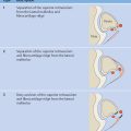
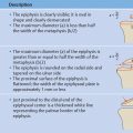
Measuring the anterior atlantodental interval ( Fig. 9.1 ): A line is drawn along the anterior arch of the atlas connecting the most posterior points of its superior and inferior borders. Then a second, parallel line is drawn along the anterior aspect of the dens. The distance between the two lines is the anterior atlantodental interval (AADI), which can be measured in the neutral position and also in flexion and extension. Values > 3 mm are considered suspicious. Widening of the AADI to > 5 mm strongly suggests rupture or inflammatory damage to the transverse atlantal ligament. In children under 8 years of age, an AADI of 4 mm is considered the upper limit of normal, especially during flexion, because the ligaments are slightly more lax in children.
Measuring the posterior atlantodental interval ( Fig. 9.2 ): A line is drawn along the posterior arch of the atlas connecting the most anterior points of its superior and inferior borders. The distance between that line and a parallel line along the posterior aspect of the dens is the posterior atlantodental interval (PADI). In patients with atlantoaxial instability due to rheumatoid arthritis, values < 10 mm are critical in terms of spinal canal encroachment and possible spinal cord compression.

Lateral Atlantodental Interval
Two techniques are available for evaluating atlantodental dislocation in the coronal plane. Both are based on a transoral odontoid view.
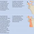
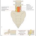
Evaluation of the lateral atlantodental interval ( Fig. 9.3 ): Draw a line tangent to the most medial point on the left and right lateral masses of C1. Measure its distance from the dens on each side, and compare the sides. Definitive cutoff values have not been published in the literature, but it should be noted that only a true anteroposterior (AP) transoral odontoid view will permit a reliable evaluation.
Measuring the displacement of the C1 lateral masses ( Fig. 9.4 ): This method is more practical and dependable. Lateral displacement signifies a possible rupture of the transverse ligament due to a Jefferson fracture. The offset of a line tangent to the lateral aspects of C1 is measured along a horizontal line drawn through the lateral margins of the articular facets of C2. Normally the lateral margins of the atlas and axis should line up with each other, even during slight neck rotation. Displacement of the C1 lateral masses by > 7 mm (adding both sides) suggests the presence of a Jefferson fracture accompanied by rupture of the transverse ligament.


Measuring the anterior atlantodental interval and evaluating displacement of the C1 lateral masses are particularly important in patients with cervical spine injuries. The posterior atlantodental interval is a key parameter in patients with destructive changes caused by inflammatory joint disease, but its role in selecting patients for surgery has been diminished by the increasing use of magnetic resonance imaging (MRI) for the detection of associated myelopathy.

Vertebral Alignment
Lateral Radiograph
Four contour lines can be used to evaluate vertebral alignment on a lateral radiograph of the cervical spine ( Fig. 9.5 ). Each of the lines should form a smooth, gentle curve with no steps or discontinuities. Approximately 20% of children have a physiologic anterior offset of C2 relative to C3 through ~ 7 years of age (“pseudosubluxation”), but good spinolaminar alignment should still be preserved.
Anterior vertebral line: formed by the anterior borders of the vertebral bodies. On radiographs it can be traced from the anterior arch of the atlas through C7. Physiologic notches or bevels in the anterior vertebral margins (apophyseal region) may create slight irregularities.
Posterior vertebral line: formed by the posterior borders of the vertebral bodies, marks the anterior boundary of the spinal canal. It can be traced from the base of the atlas through C7. An electronic display with windowing options can often show the posterior margin of the dens as an upward prolongation of the line.
Spinolaminar line: formed by the junction of the C1 through C7 spinous processes and laminae, marks the posterior boundary of the spinal canal. The posterior arch of C1 may be a few millimeters anterior to the spinolaminar line as a normal variant. The line extends upward to the posterior rim of the foramen magnum.
Posterior spinous line: formed by the tips of the C2 through C7 spinous processes. The distance between the C2 and C3 spinous processes is physiologically smaller than in the other segments.

Thiebaut and Wackenheim described the basilar line, also called the Wackenheim clivus line, which represents a downward extension of the posterior surface of the clivus. This line should be tangent to the posterior cortex of the tip of the dens or should cross the dens at the junction of the anterior and middle thirds of the tip. Deviations from this alignment are evidence of atlanto-occipital dislocation. The normal variability of the clivus slope makes this technique very unreliable, however.

A practical alternative for the diagnosis of atlanto-occipital dislocation is to measure the basion–dens interval and basion–axial interval ( Fig. 9.6 ). Harris in 1994 evaluated these intervals on lateral radiographs of 37 patients with known atlanto-occipital dislocation and a control group of 400 adults with no occipitovertebral abnormalities. The basion–dens interval is determined by measuring the distance between the basion (caudal tip of the clivus) and the highest point on the dens. The basion–axial interval is measured between the basion and a line along the posterior surface of the dens. For both measurements, an interval > 12 mm is considered evidence of atlanto-occipital dislocation. This is a valid cutoff value for the basion–axial interval even on flexion and extension views. In rare cases the clivus may be physiologically up to 4 mm behind the line along the posterior cortex of the dens. Because the dens is not fully ossified until about age 12 years, it is recommended that the basion–dens interval be measured only in patients aged 14 years or older. By contrast, the basion–axial interval can be measured in younger children.
Wackenheim A. Roentgen Diagnosis of the Cervical Vertebral Region. New York: Springer; 1974 Thiebaut F, Wackenheim A, Vrousos C. La ligne basilaire: etude d′une ligne d′orientation verticale pour la reconnaissance des displacements anterieurs et posterieurs de la dent de l′axis dans des malformations et traumatismes de la charniére cervico-occipitale. Sem Hop Paris 1963;3–4:43–46Related posts:
Stay updated, free articles. Join our Telegram channel

Full access? Get Clinical Tree


