LEARNING OBJECTIVES
1. Quality assurance and quality control requirements under Mammography Quality Standards Act (MQSA)
• Tests done by the technologists and the required frequency
Actions required if tests fail
• Tests done annually by the physicist
• Phantom images
• Films labeling
Required under MQSA
Recommended
2. Indicated imaging algorithms in screening
• Standard views
• Additional images done in women with implants
• Exaggerated craniocaudal views laterally
• Anterior compression views
• Imaging women with small or large breasts
3. Positioning basics
• Mediolateral oblique (MLO) views
• Craniocaudal (CC) views
• Exaggerated craniocaudal views
4. Assessing adequacy of positioning
• MLO views
• CC view
Posterior nipple line measurement
• Exaggerated craniocaudal views
5. Assessing images for motion
6. Artifacts related to
• Equipment
• Software processing
• Patients
7. Screening
• Definition
• Standard views
• Viewing conditions
• Approach to lesion detection
8. Evaluation of images
• Technical adequacy of images
Positioning
Exposure
Contrast
Motion (Sharpness)
Noise
Compression
Film labeling
Artifacts
• Review images in totality for global changes
Size asymmetry
Diffuse trabecular or parenchymal changes
Technical factors used for exposure
Focal and global areas of parenchymal asymmetry
• Review images specifically looking for
Masses (correlating size and distance from nipple on CC and MLO views)
Calcifications
Distortion
• Review images in thirds
CC: lateral, retroareolar, medial
MLO: upper, mid and lower
• Review specific locations
CC: medial quadrants, subareolar, retroglandular fat and tissue interface
MLO: fatty strip between pectoral muscle and tissue, subareolar, upper cone of tissue, tissue immediately superior to inframammary fold (IMF)
CC and MLO: all fat-glandular tissue interfaces
Under the Mammography Quality Standards Act (MQSA) (1), mammographic facilities are required to have a quality assurance (QA) and quality control (QC) program. For digital systems, facilities need to implement the QA/QC program as specified by the manufacturer of the unit(s) being used (1,2). Weekly quality control tests typically include DICOM printer quality control, detector flat-field calibration to assure the system is calibrated properly, artifact evaluation (for the detector), signal-to-noise and contrast-to-noise measurements to assure consistency of the digital image receptor, phantom image to assure overall image quality, compression thickness indicator to assure indicated compression thickness is accurate to ±0.5 cm from actual thickness, diagnostic review workstation QC, and viewboxes and viewing conditions. The visual checklist, repeat analysis, and compression QC test are done monthly, quarterly, and semiannually, respectively. The annual tests done by physicists typically include mammographic unit assembly evaluation, collimation assessment, artifact evaluation, kVp accuracy and reproducibility, beam quality assessment (half-value layer [HVL] measurement), evaluation of system resolution, automatic exposure control (AEC) function performance, radiation output rate, phantom image quality evaluation, signal-to-noise and contrast-to-noise measurements, diagnostic review workstation QC, breast entrance exposure, AEC reproducibility, and average glandular dose. Evaluation of detector ghosting is optional. The reader is advised to consult the equipment manufacturers’ QC manual for details on the specific tests required as well as how each test should be done and interpreted.
For facilities using film-screen systems, QC tests that need to be done by the technologist daily, monthly, quarterly, and semiannually and the annual tests required of the physicist are detailed under the MQSA (1) and the American College of Radiology’s (ACR) Mammography Quality Control Manual (3). The reader is advised to consult this manual for details on how each test is done and interpreted.
PHANTOM IMAGES
A basic understanding of the phantom image in mammography is important since this is used routinely to ensure the entire imaging system (and the processor if film-screen mammography is in use) is operating optimally with respect to uniformity, lack of artifacts, and overall image quality. As part of the QA/QC program, phantom images are done weekly. These are also done after the equipment is serviced, when film or screen type is changed (for facilities doing film-screen mammography) or as needed when troubleshooting problems with the imaging chain. The reader is encouraged to review and understand how phantom images are obtained, evaluated, and scored (ACR’s Mammography Quality Control Manual) (3). The phantom (Radiation Measurement, Inc. RMI 156 or Nuclear Associates 18-220) simulates a 4.2-cm-thick compressed breast composed of 50% glandular and 50% fatty tissue. It contains six fibers (range, 1.56 to 0.4 mm), five specks (1.56- to 0.4-mm diameter range), and five masses (2.00- to 0.25-mm diameter range). An acrylic disc (4-mm thick, 1-cm diameter) is placed, or permanently attached to the phantom.
At a minimum, the four largest fibers, three largest speck groups, and three largest masses should be seen (Fig. 2.1). The image is also reviewed for artifacts and these are factored into the scoring. Regions of interest (ROI) are placed one over the disc and the other in an area adjacent to disc so that signal-to-noise ratios (SNR) and contrast-to-noise ratios (CNR) can be calculated. The measured SNR must be equal to or greater than 40 and the CNR must be within ±15% of the value determined by the medical physicists when the image receptor was installed or after any major upgrade. If the criteria specified by the equipment manufacturer are not met, the service engineer needs to be contacted before any further clinical imaging is done.

FIG. 2.1 • Phantom image. Radiation Measurement, Inc. (RMI 156) phantom. For our system, five fibers (black arrow), four speck groups (long white arrow), and four masses (short white arrow) need to be seen to pass. In addition, the image is reviewed for homogeneity and artifacts. The acrylic disc (D) attached to the phantom is used to calculate SNR and CNR. As part of the QA/QC program, phantom images are done weekly, and the images are retained for one full year.
FILM LABELING
Mammography films are legal documents and must be labeled appropriately as required under MQSA (1). The information that must be included on the images is listed in Table 2.1. When printing images from a digital study, please make sure that the required data is not printed over any part of the breasts or pectoral muscles.
Technical factors (kVp, mAs, cm of compression) used for exposure should be available readily so that they can be reviewed in conjunction with the images. As will be discussed and illustrated repeatedly, the technical factors used for exposure (right breast compared with left or from 1 year to another) in some patients provide additional information that can be used in establishing the presence of underlying pathology and formulating differential considerations.
IMAGING ALGORITHM
By definition, screening mammography is done in asymptomatic women (4). We recommend annual screening mammography starting at age 40. In women with a strong family history of breast cancer, we start screening annually at age 30. Additionally, if a patient has two first-degree relatives with breast or ovarian cancer, particularly if the diagnosis of breast cancer in the relative occurred premenopausally, she is referred to a genetic counselor for risk assessment. If the risk assessment yields a 20% or higher lifetime risk for breast cancer, we recommend annual screening with mammography and breast magnetic resonance imaging (5).
Table 2.1 REQUIRED INFORMATION ON IMAGES
Patient name Unique patient identifying number Date of study Radiopaque laterality and projection markers placed closest to axilla Facility name Facility location (minimum: city, state, and zip code) Technologist identification Mammography unit identification number/room number (if more than one unit/facility) |
Craniocaudal (CC) and mediolateral oblique (MLO) views of each breast are done for screening (4). At the discretion of the technologist, anterior compression and exaggerated craniocaudal (XCCL) views are obtained in a small number of women to adequately compress anterior tissue and image posterolateral tissue in the CC projection, respectively. A metallic BB is used to mark any prominent skin lesions that may be mistaken for a breast mass. Our technologists are required to document the location and reason for using skin markers on the patient’s history form. Likewise, they document surgical scars on a diagram of the breast provided on the history form. We do not routinely use radiopaque markers on biopsy scars or the nipples (see excisional biopsy section in Chapter 11 for additional discussion).
In women with implants, we obtain four views of each breast: CC and MLO views with the implants in the field of view and CC and MLO views with displacement of the implants (1,3,4,6). Implant-displaced (ID) views may be difficult (or not possible) to obtain in women with implants that are encapsulated (see Fig. 11.49). If the ID views cannot be done, the technologist documents this in the patient’s history form and the radiologist states this in the breast imaging consultation report. We do not obtain any special consent from patients with implants prior to imaging them.
IMAGING WOMEN WITH SMALL BREASTS (OR MEN)
In women with small breasts, for ID views in some women, or in male patients, it can be hard for the technologist to maintain breast positioning, particularly for MLO views, without potentially hurting her hand and scraping the skin over her knuckles as compression is applied. After positioning, the technologist holds the breast in position, and as the paddle comes down on the breast, she needs to pull her hand out from under the paddle. This maneuver can be a challenge when using the standard compression paddle in these groups of patients. To overcome these potential limitations, a compression paddle that is half the width of the standard compression paddle is available (Fig. 2.2A); this paddle is also sometimes helpful in obtaining optimal axillary views.
IMAGING WOMEN WITH LARGE BREASTS
For most digital systems, compression paddles (Fig. 2.2B, C) with resulting collimation are available in two sizes (18 × 24 cm and 24 × 30 cm). The selection of which size to use is made based on the woman’s breast size. The large paddle and the resulting larger field of collimation is not used for women with small breasts. Likewise, the small paddle and small field of collimation is not used on a woman with large breasts. Some women with large breasts may need more than two views of each breast to image all the breast tissue adequately in the two standard projections (Fig. 2.3).
MEDIOLATERAL OBLIQUE VIEWS
Factors to be considered in obtaining optimal positioning of the breasts on MLO views are listed in Table 2.2. If these simple concepts are followed routinely, a maximal amount of tissue is included on the images while compression-related discomfort is minimized.

FIG. 2.2 • Compression paddles, screening. A: This compression paddle is half the width of the standard 18 × 24 cm paddle. It is particularly helpful in imaging women with small breasts, men, and for ID views in some patients with implants. It is also sometimes used for axillary views. B: Standard 18 × 24 cm compression paddle. C: Larger, standard 18 × 30 cm compression paddle. Although this larger paddle facilitates the imaging of some women with no extra views, some patients may still require more than two images to adequately include all of the tissue in the two standard projections. The red markings centrally on the paddles indicate available photocell positions with the particular unit being used.

FIG. 2.3 • Tissue exclusion, need for additional views to include all tissue in standard screening projections. MLO view, left breast. Although the 18 × 30 cm paddle is used for this image, anterior and inferior tissue is excluded and as such additional views are needed to be able to evaluate all of the breast tissue in two projections.
In positioning patients for MLO views, four separate concepts need to be considered, understood, and applied consistently: selection of a patient-specific angle of obliquity, relaxation of the pectoral muscle, medial mobilization of the breast and underlying pectoral muscle, and the need for an out and upward pull of the breast tissue and underlying muscle. The breasts are skin appendages. In trying to maximize the outward pull of a skin appendage so it can be imaged, it is best to pull the appendage out parallel to the underlying muscle; the pectoral muscle is the muscle underlying the breast. Consequently, the technologist needs to assess the orientation of the pectoral muscle for the individual patient (Fig. 2.4) and use this to determine the angle of obliquity for the MLO view. By necessity, the angle will be different for different patients. Tall women will have a more vertically oriented pectoral muscle compared to short women. In an effort to include as much tissue as possible on MLO views, the breasts should be pulled away from the body parallel to an underlying relaxed pectoral muscle (7).
Table 2.2 FACTORS TO BE CONSIDERED IN POSITIONING FOR MLO VIEWS
Technologist works from behind and the medial side of patient Angle of obliquity Specific for each patient Determined by technologist based on the obliquity of the pectoral muscle Relaxation of the pectoral muscle Inward rotation of humeral head Ipsilateral arm down Medial mobilization of breast tissue and pectoral muscle Need to maintain medial mobilization Minimizes skin stretching in the upper inner quadrant Patient needs to stay in unit (tendency is to pull back out) Breast pulled up and out Open IMF Include a small amount of abdomen |

FIG. 2.4 • Determining angle of obliquity for MLO view. With the patient’s arm relaxed as she stands by the digital detector, the technologist can determine the optimal angle of obliquity and adjust the gantry accordingly for the MLO views. The angle of obliquity used for the MLO views is based on the patient’s body habitus and orientation of the underlying pectoral muscle; it is different for different patients.
In addition to selecting an appropriate angle of obliquity, the technologist needs to make sure that the pectoral muscle is relaxed; otherwise, she may be fighting the resistance added by a tense muscle. The pectoralis major muscle inserts on the upper third of the humerus; so the muscle tenses if the arm is elevated and the humeral head is externally rotated. During positioning, the patient’s arm should be kept down (behind or on the bucky) while making sure that she inwardly rotates her humeral head. The amount of tissue and muscle included on the images is increased if the pectoral muscle is relaxed.
With respect to the importance of breast mobility, consider the basics of breast anatomy. The lateral and inferior aspects of the breasts are the most mobile (Fig. 2.5A). Tissue in the upper and particularly inner quadrants has little inherent mobility. Unfortunately, most of our equipment is designed so that, for MLO views, the compression paddle travels from the upper inner quadrant toward the lower outer quadrant (Fig. 2.5B). As the compression paddle is engaged, we are attempting to mobilize tissue with little inherent mobility in the upper inner quadrants into the field of view. Inevitably, as the compression paddle moves, tissue and potentially lesions roll out from under the paddle and are excluded from the field of view. The movement of the compression paddle over fixed tissue in the upper inner quadrant of the breast also results in skin stretching that almost certainly accounts for much of the discomfort patients associate with mammography and attribute to breast compression. If we use natural breast mobility effectively, we can minimize the amount of tissue that is excluded as well as the amount of skin stretching (7). Every 1 mm that we are able to mobilize tissue and underlying muscle medially represents 1 mm less of the compression paddle travelling over fixed tissue. In addition to mobilizing the breast and muscle medially, the breast tissue needs to be actively pulled out away from the body to include a maximal amount of posterior tissue, and upwardly, so that the inframammary fold (IMF) is opened. Ideally, a small amount of upper abdomen is included on the image.

FIG. 2.5 • Breast mobility. A: Lateral and inferior breast tissue is mobile. Upper and medial breast tissue has little inherent mobility. During positioning, tissue should be mobilized so as to minimize the amount of fixed tissue passed over by the compression paddle. B: For the MLO view, the compression paddle moves from the upper inner quadrant toward the lower outer quadrant. With little inherent mobility, upper inner quadrant tissue is excluded from the field of view as the compression paddle is mobilized for the MLO views. The skin is stretched and sometimes scraped as the paddle moves over this tissue. Similarly, for craniocaudal (CC) views, the compression paddle moves from upper to lower quadrants. As the paddle moves downward, superior tissue, and possibly lesions, can roll out from the under the paddle. Skin stretching, resulting from the compression paddle scraping over this portion of the breast, accounts for some of the discomfort patients associate with breast compression. (From Cardeñosa G. Breast Imaging [The Core Curriculum Series]. Philadelphia, PA: Lippincott Williams & Wilkins; 2003.)
The tip of the digital detector is positioned at the apex of the axilla so that it is snug against the body along the mid-axillary line. As the patient is rotated toward the digital detector and the breast is mobilized, the technologist needs to smooth the tissue going up against the detector; otherwise, skinfolds can develop (Figs. 2.6 and 2.7A). Also, there should be no air gap (Fig. 2.7A) between the pectoral muscle and upper portion of the breast and the digital detector. If the air gap is not cleared, uneven exposure (overexposure) of the pectoral muscle and axillary tissue will be apparent (Fig. 2.7A, B). Last, there should be no space between the digital detector and the breast posteriorly (Fig. 2.7C); otherwise, posterior tissue is excluded. The technologist should not be able to advance her index finger into the apex of the axilla.
If the correct angle of obliquity for the individual patient is selected, the pectoral muscle is relaxed, the breast is medially mobilized and maintained there as the breast is pulled up and out, the amount of tissue included on the MLO view is maximized, and exclusion of tissue, particularly upper inner quadrant tissue, is minimized. In assessing the adequacy of positioning on MLO views, the interpreting radiologist should consider the factors listed in Table 2.3. Consider the length and shape of the pectoral muscle on the MLO views (8). The pectoral muscle should be thick (wide) at the axilla, have an anterior convex margin, and extend to the level of the nipple (Fig. 2.8). Selection of an inappropriate angle of obliquity, inadequate relaxation of the muscle, failure to medially mobilize or maintain medial mobilization of breast tissue, or allowing the patient to lean back slightly can result in a concave pectoral muscle edge, a triangular pectoral muscle, or a muscle that is parallel to the edge of the film (Fig. 2.9). The IMF should be open with a small amount of abdomen included on the image. The technologist should exercise care to not include too much abdomen, or allow a skinfold (Fig. 2.6) to develop up against the bucky laterally, since this may limit compression. A small triangular density superimposed on the pectoralis major muscle in a small number of women is the pectoralis minor muscle (Fig. 2.10).

FIG. 2.6 • Skinfold. MLO views photographically coned to superior tissue. Skinfold develops laterally as the breast is being mobilized medially. Since the skinfold develops on the portion of breast up against the digital detector, it is not readily apparent to the technologist during positioning. Air (lucency) outlines the edge of the skinfold (arrows). When skinfolds are present, compression may be compromised; consequently, the tissue surrounding a skinfold needs to be evaluated carefully for motion (blur). If the skinfold is adequately penetrated, and there is no associated blur, it is not absolutely necessary to repeat the image. (From Cardeñosa G. Breast Imaging [The Core Curriculum Series]. Philadelphia, PA: Lippincott Williams & Wilkins; 2003.)

FIG. 2.7 • Positioning, MLO views. A: In positioning the patient’s breast for the MLO view, breast, pectoral muscle, and axillary tissue need to be directly in contact with the digital detector. If the tissue is not flush on the detector, the resulting air gap (black oval) leads to suboptimal breast compression and apparent overexposure of axillary tissue and pectoral muscle. Also, the technologist needs to be sure no skinfolds develop in the tissue (arrows) going up against the detector. B: Uneven exposure (arrows) resulting from the presence of an air gap between axillary tissue and the detector (e.g., the tissue was not directly up against the detector). When areas of uneven exposure are seen related to air gaps, compression of the tissue in the area is not optimal and as such the tissue needs to be evaluated carefully for blur. Arterial calcification is noted incidentally. (From Cardeñosa G. Breast Imaging [The Core Curriculum Series]. Philadelphia, PA: Lippincott Williams & Wilkins; 2003.) C: The corner of the detector is in the apex of the axilla and the edge of the detector is flush with the skin along the mid-axillary line. The technologist should not be able to interpose her fingers between the detector and the patient in the axilla or along the edge of the detector.
Table 2.3 ASSESSING POSITIONING ON MLO VIEWS
Wide (thick) pectoral muscle (PM) at the axilla PM to level of nipple Convex anterior margin of PM Breast pulled up and out (no sagging) Open IMF Small amount of upper abdomen |
In some women, positioning may be limited secondary to a physical disability such as kyphosis, paraplegia, a frozen shoulder, Parkinson disease, or absence of the pectoral muscle (Poland syndrome) (9) (Fig. 2.11A, B). In these situations, we work closely with the patient to obtain the best images possible and document the limitations and our efforts to obtain adequate images on the patient’s history form. If the limitations are significant, we describe this in our breast imaging consultation report. In contrast to patients with Poland syndrome in whom there is absence of a pectoral muscle, rarely, in patients with a history of prolonged steroid (Fig. 2.11C) exposure, or those with disuse (e.g., paralysis of the ipsilateral arm, polio) of the chest wall musculature (Fig. 2.11D), it may appear as though there is no pectoral muscle, yet on close review of the images, the “ghost” of a pectoral muscle is apparent as the striations of the pectoral muscle are seen in an otherwise fatty replaced muscle.

FIG. 2.8 • MLO views. The pectoral muscles are thick in the axillae; the anterior borders are convex and extend to the level of the nipples. The tissue is pulled up and out, adequately compressed, and optimally exposed. The IMFs are open. (From Cardeñosa G. Breast Imaging [The Core Curriculum Series]. Philadelphia, PA: Lippincott Williams & Wilkins; 2003.)
CRANIOCAUDAL VIEWS
Factors to be considered in obtaining optimal positioning of the breasts on CC views are listed in Table 2.4. If these concepts are followed routinely, a maximal amount of tissue is included on the images and compression-related discomfort is minimized.
In positioning patients for CC views, several concepts need to be considered, understood, and applied consistently: upward mobilization of the breast to the extent permitted by the natural mobility of the IMF, placement of the imaging receptor up against the chest wall, positioning of the contralateral breast on the image receptor, outward pull of the breast, and the lateral tug. In considering the CC view, keep in mind that the breast is mobile inferiorly while upper tissue, particularly close to the chest wall, is relatively fixed in position. Yet, when the compression paddle is engaged, it moves over upper inherently fixed tissue posteriorly in an attempt to mobilize it inferiorly. The technologist should identify the natural position of the IMF as she holds and lifts the breast as far as the natural mobility of the IMF allows. If the technologist is able to mobilize the breast upward to meet the paddle, exclusion of upper posterior tissue can be minimized. Every millimeter the breast is moved upward to meet the paddle is 1 mm less that the paddle will need to move down over fixed tissue (7); this results in inclusion of a maximal amount of tissue and minimizes skin stretching and the associated discomfort. The image receptor should not be placed higher than the elevated IMF position; otherwise, posterior tissue is excluded. As the breast is lifted, the technologist needs to be careful so that a skinfold doesn’t develop between the inferior aspect of the breast and the IMF or that a portion of abdomen is not included on the image. When present, this skinfold (or abdomen) can simulate the pectoral muscle. A sharp lucency (air) outlines the edge of a skinfold but is not seen associated with the pectoral muscle (Fig. 2.12). Also, as the breast is lifted upward it also needs to be actively pulled out away from the body.

FIG. 2.9 • The pectoral muscle shape and MLO views. A: Evaluation of the pectoral muscle is helpful in assessing positioning on MLO views. Ideally, as illustrated on the right MLO (RMLO), the pectoral muscle is thick in the axilla, with a convex anterior border that extends to the level of the nipple. To accomplish this with a cooperative patient, the technologist determines the angle of obliquity based on the orientation of the pectoral muscle for the individual patient. The technologist needs to make sure that the pectoral muscle is relaxed, mobilized medially, and maintained there as compression is applied. If the patient moves back slightly out of the machine, the pectoral muscle is thin and parallel to the edge of the image as illustrated on the left MLO (LMLO). B: If an incorrect angle of obliquity is selected or the muscle is not relaxed, the muscle may have a concave contour as illustrated on the right MLO or be triangular in shape as shown on the left MLO. For each of these, inferior and posterior tissue may have been excluded from the image. (From Cardeñosa G. Breast Imaging [The Core Curriculum Series]. Philadelphia, PA: Lippincott Williams & Wilkins; 2003.)

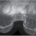
FIG. 2.10 • Pectoralis minor muscle. A triangular density superimposed on the pectoral major muscle is the pectoralis minor muscle (thin arrows). In this woman, the pectoralis minor muscle is seen bilaterally. The pectoralis minor muscle is imaged in a small percentage of women and is sometimes only imaged on one side. A skinfold is noted on the left (thick arrow). Also note air gap with uneven exposure particularly prominent on the left. (From Cardeñosa G. Breast Imaging [The Core Curriculum Series]. Philadelphia, PA: Lippincott Williams & Wilkins; 2003.)
The position of the contralateral breast needs to be considered. If the contralateral breast is left pendulous, it can become an impediment to the digital detector being placed against the chest wall. The technologist needs to place the contralateral breast on the edge of the imaging receptor so that the detector can go up against the chest wall (Fig. 2.13A). The technologist should check to make sure there is no space (air gap) between the chest wall and digital detector; she should not be able to put her index finger through the cleavage (Fig. 2.13B).

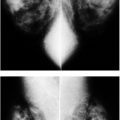
FIG. 2.11 • Poland syndrome and fatty replaced pectoral muscles. CC (A) and MLO (B) views from a screening study. The left breast is smaller than the right. No pectoral muscle is imaged on the left MLO view. As in this patient with Poland syndrome, the breast on the affected side is usually smaller than the contralateral breast. Other ipsilateral chest wall abnormalities, including absence of the clavicle, may be seen in patients with Poland syndrome. (From Cardeñosa G. Breast Imaging [The Core Curriculum Series]. Philadelphia, PA: Lippincott Williams & Wilkins; 2003.) C: MLO views in a different patient. On initial review, you might think the patient is missing the pectoral muscles bilaterally or that positioning is suboptimal with triangularly shaped muscles high up on the image; however, on close review, striations are noted on the MLO views (arrows) in largely fatty replaced pectoral muscles. Less fat replacement is seen superiorly in the muscle particularly on the right. This patient has a long history of steroid use. The round radiopaque marker seen on the right MLO is marking a skin lesion. D: MLO views in a different patient. You might initially think this is a patient with Poland syndrome with no pectoral muscle on the left, however, if you look carefully you can see the “ghost” of the pectoral muscle with internal striations. This patient has a history of polio with limited mobility on the left side of her body resulting in disuse atrophy. Morphologically normal-appearing lymph nodes are seen in the left axilla.
The inclusion of medial tissue on CC views needs to be emphasized; however, as much as 2 cm of lateral tissue can be pulled into the image without giving up medial tissue (Fig. 2.14). The lateral aspect of the breast is mobile and has to be pulled actively into the image by the technologist as compression is applied. As the lateral aspect of the breast is tugged, a skinfold often develops laterally. This skinfold can sometimes be rolled out if the technologist puts her finger under the paddle and rolls it out with the skinfold.

Table 2.4 FACTORS TO BE CONSIDERED IN POSITIONING FOR CC VIEWS
Technologist works from medial side of patient Neutral position of IMF is identified Breast tissue is lifted to the extent of natural mobility of IMF Pull breast tissue out Lateral tug: active pull of lateral tissue into field of view Contralateral breast up on digital detector (not left pendulous) Detector to chest wall In women with no history of breast surgery the nipple should point straight out Suspect medial exaggeration if nipple is pointing laterally Suspect lateral exaggeration if nipple points medially |

FIG. 2.12 • Skinfold. As the breast is mobilized upward for positioning on CC views, a skinfold can develop inferiorly or a portion of the abdominal wall is included on the image. This skinfold simulates the pectoral muscle, however, if evaluated carefully, air (lucency) outlines the skinfold (short arrows) on the left CC view; this lucency is not seen outlining the anterior contour of the pectoral muscle (long arrows) on the right. Since the skinfold develops up against the digital detector inferiorly, the technologist does not see it during positioning. (From Cardeñosa G. Breast Imaging [The Core Curriculum Series]. Philadelphia, PA: Lippincott Williams & Wilkins; 2003.)

FIG. 2.13 • Positioning, CC views. A: In positioning the breast for a CC view, the contralateral breast should be draped over the edge of the digital detector. If the breast is left pendulous, it becomes an impediment to the imaging receptor being placed as far posteriorly as possible. B: If the technologist is able to advance her fingers through the cleavage as is demonstrated on this image, posteromedial tissue is being excluded from the field of view. Note that on this image the contralateral breast is not on the imaging receptor but rather has been left pendulous.

In women who have had no breast surgery, the nipple can be used as an indicator of unwanted exaggeration on CC views. In an optimally positioned CC view, the nipple should point straight out. If the nipple points medially, there may be lateral exaggeration and similarly, if the nipple points laterally, medial exaggeration may be present. Caution should be exercised, however, because in women with significant tissue mobility laterally, a routine CC may seem exaggerated laterally when it is not; the apparent exaggeration laterally is a reflection of an optimal lateral tug.
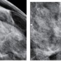
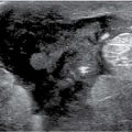
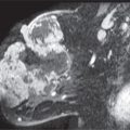
In assessing the adequacy of positioning on CC views (Table 2.5), pectoral muscle should be seen in 30% to 40% of patients (7,8) (Fig. 2.15A); in younger women, the pectoral muscle may be imaged more commonly than in older patients. If the pectoral muscle is not seen, look for cleavage (Fig. 2.15B). If pectoral muscle or cleavage is seen, you are assured that medial tissue has not been excluded from the image; if neither is seen, consider measuring the posterior nipple line (PNL) (see below). Laterally, retroglandular fat should be seen; if tissue is seen to the edge of the film, an XCCL view may be indicated.
In some women, the pectoral muscle is atrophied and only the sternal insertion is seen medially on the CC view. The rounded or triangular appearance of the muscle in these women can simulate the anterior portion of a mass (Fig 2.16) (10). Alternatively, a round density partially seen on the CC view medially superimposed on the pectoral muscle (with no correlate on the oblique view) can represent the sternalis muscle (Fig. 2.17; also see Fig. 10.1). Even with spot compression views, it is usually only partially seen. The sternalis muscle is an uncommon normal variant in chest wall musculature; it is the remnant of a muscle that would extend from the infraclavicular region to the caudal aspect of the sternum (11). It is commonly a unilateral finding. When the MLO view is reviewed in these patients, no abnormality is seen.

FIG. 2.14 • Lateral tug for CC view. Invasive ductal carcinoma. MLO (A) and CC (B) views photographically coned to the upper and lateral portions of the images, respectively. A mass is seen on the right MLO view (arrow). It is partially imaged on the CC view (thin arrow). Pectoral muscle is seen (thick arrow) centrally on the CC views. C: Repeat right CC view with attention to the lateral tug. The mass (short arrow) and additional posterior tissue, including a lymph node (long arrow), are now included on the image. During positioning for CC views, the technologist needs to actively pull on the lateral aspect of the breast to include as much tissue as possible into the image. This will increase the amount of lateral tissue that is imaged without sacrificing the inclusion of medial tissue. (From Cardeñosa G. Breast Imaging [The Core Curriculum Series]. Philadelphia, PA: Lippincott Williams & Wilkins; 2003.)
Table 2.5 ASSESSING POSITIONING ON CC VIEWS
Related posts:
Stay updated, free articles. Join our Telegram channel

Full access? Get Clinical Tree


