Fig. 4.1
Bird’s-eye view of the HIMAC facility
The HIMAC facility has employed a single beam-wobbling method, which is one of the passive beam delivery methods [10], as shown in Fig. 4.2. This beam delivery method consists of two components; a single beam-wobbling system for a lateral dose spread and a ridge-filter method for the creation of spreadout Bragg peak (SOBP). A pair of beam-wobbling magnets (wobbler) moves the beam in a circular orbit with high frequency so as to generate a pseudo-stationary broad beam in conjunction with a heavy-metal scatterer. An exchangeable ridge filter modulates the beam range in the field to spread out the Bragg peak longitudinally. A range shifter system inserts variable-thickness energy absorbers to adjust the beam range. A multi-leaf collimator (MLC) with movable metal elements and/or a customized patient collimator defines the field aperture. A patient compensator, a sculptured plastic device, compensates the beam ranges so that the beam range conforms with the distal part of the target volume in the field.
Fig. 4.2
Typical beam delivery system with the beam-wobbling method as one of the broad-beam methods
In the HIMAC beam delivery system, the wobbling frequency is set to be 56.4 Hz, and the ridge filter consisting of identical aluminum bar ridges spreads the beam range to give a uniform biological dose to the SOBP region. In the case of a heavy-ion beam, the SOBP is composed of various LET components with different weighting factors at each depth. The cell survival rate under a mixed LET radiation field can be described by a formalism proposed in the theory of dual radiation action on the basis of the Linear Quadratic (LQ) model [11], which was experimentally proven. We finally designed the SOBP of mixed ions with different LET according to the procedure proposed by Lawrence Berkley National Laboratory (LBNL) [12] and the formalism [11]. At HIMAC, applying the single beam-wobbling with ridge-filter method, the maximum lateral field and the SOBP size are designed to be 22 cm in diameter with ±2.5 % of uniformity and 15 cm at the isocenter, respectively.
The single beam-wobbling method is a very robust method against fluctuations of beam position and/or intensity, compared with a pencil-beam 3D scanning one. The HIMAC beam delivery system, therefore, has employed this method in order to deliver its dose safely and reliably. On the basis of this method, the respiratory-gated and layer-stacking irradiation methods were developed in order to increase the irradiation accuracy, which have been routinely used for treatments in HIMAC. The beam-wobbling method was improved, further, to increase the residual range, and beam utilization efficiency.
4.2.2 Respiratory-Gated Irradiation Method
Damage to normal tissues around tumor is inevitable in treatment of a tumor moving along with a patient’s respiration. Therefore, a respiratory-gated irradiation method with a broad beam was developed [13].
Essential design considerations are as follows:
1.
A gate signal for permitting irradiation should be accurately generated to enable irradiation only when target is at the desired position. For this purpose, a position-sensitive detector (PSD) with an infrared light source is chosen to generate the respiration signal because of its reliability, stability, and easy setting. Since the organs are normally most stable at the end of expiration, the permitting signal for irradiation should be generated during this phase. The gate signal, on the other hand, is generated by the AND logic between the irradiation-permitting signal and the flattop period than can extract the beam from the synchrotron.
2.
An operation pattern of the synchrotron should be optimized to give maximum effective dose rate. A duty factor of the beam delivery in a 0.3-Hz operation pattern, thus, is to increase more than 50 % in order to avoid a beat between the flattop period and the permitting irradiation period.
3.
An aborting system of residual beam in the flattop of the synchrotron operation pattern should be provided to avoid unwanted activation. In the beam-aborting system, a beam deceleration scheme was employed and a residual beam is decelerated from a top energy to an injection-energy level.
4.
An interlock system for a safe treatment should be used. An interlock function, thus, is added to the interlock system used for treatment of a fixed target so as to work immediately when irradiation dose in a non-permitting-irradiation period exceeds a threshold level.
A block diagram of this system is shown in Fig. 4.3. As shown in the lower-left corner in Fig. 4.3, an infrared-LED sensor is set on the surface of patient body, and its movement is monitored by a position-sensitive detector, which results in obtaining a respiratory signal. The gate signal, which is a permitting signal of irradiation, is generated by AND logic between the respiratory signal and the flattop signal of the synchrotron operation (upper right in Fig. 4.3). The beam should be delivered according to the gate signal produced only when the target is in its designated position (upper left in Fig. 4.3). One of the most essential technologies for the system is a slow beam extraction method having a quick response on the beam on/off compared with a respiration period. For this purpose, the RF-KO slow extraction method [14] was developed and its response on the beam on/off is within 1 ms. This irradiation method has been successfully applied since 1996.

Fig. 4.3
The view of respiratory-gated irradiation in the horizontal beam delivery system in the HIMAC facility
4.2.3 Layer-Stacking Irradiation Method
In the single beam-wobbling method, the fixed SOBP produced by the ridge filter results in undesirable dosage to the normal tissue in front of target, because the thickness of an actual target varies within the irradiation field. In order to suppress the undesirable dosage, thus, the layer-stacking irradiation method was developed [15]. A schematic drawing of this method is shown in Fig. 4.4. This method is to conform a variable SOBP to a target volume by controlling dynamically the conventional beam-modifying devices. The thin SOBP with several mm in water-equivalent length, which is produced by a ridge filter, is longitudinally positioned over the target volume in a stepwise manner. The target volume is longitudinally divided into slices, to each of which the small SOBP is conformed using the MLC and the range shifter, and a variable SOBP coinciding to the target volume is to be formed. This method has been routinely utilized since 2004. Figure 4.5 shows the simulation result to compare between dose distributions with and without this method. It is obviously found that the undesired dose region is eliminated when the layer-stacking method is applied.


Fig. 4.4
Schematic drawing of the layer-stacking irradiation method
Fig. 4.5
The dose distributions without and with the layer-stacking irradiation method. The left figure shows the dose distribution without this method, which can be easily found to have an undesired dose region (red line) outside the target. The right one shows that this method can eliminate the undesired dose
4.2.4 Improvement of Beam-Wobbling Method
The single beam-wobbling method has been utilized for the HIMAC treatment, because this method has offered both the robustness toward beam errors and the easy dose delivery management. However, it is inevitable to lose the residual range due to the scatterer. NIRS, thus, proposed the improved methods, which are spiral beam-wobbling and zigzag beam-wobbling methods [16]. As shown in Fig. 4.6, both the methods employ smaller beam size than that in the single beam-wobbling to deliver a uniform dose distribution in the lateral direction, while the beam moves along on a spiral orbit or on a zigzag one, respectively. The range loss due to passing through the scatterer is smaller because the smaller beam size requires thin scatterer. Consequently, these methods require the lower energy delivered from the accelerator to obtain a required field size, compared with that in the single beam-wobbling method.
Fig. 4.6
Schematic figures of the single beam-wobbling method, the spiral one and the zigzag one
The spiral beam-wobbling method should be required the amplitude modulation of the excitation current of the wobbler magnets, because the wobbling radius is proportional to the square root of time under the condition of a constant irradiation area in unit time. The time structure of the beam slowly extracted from the synchrotron disturbs the uniformity of a dose distribution. An angular frequency of beam wobbling should be optimized in order to avoid such disturbance. As a result of a simulation study [17], both the amplitude modulation and angular frequencies are optimized to be 59 Hz and 23 Hz, respectively.
The zigzag beam-wobbling method is raster scanning with a broad beam. The beam moves along on a zigzag pattern generated by the excitation current with a triangular waveform for the wobbler magnets. The orthogonal wobbler magnets are generally set at the slow and fast wobbling speeds, because beams scan in the irradiation field as uniformly as possible to improve the time characteristic of uniformity in the irradiation field. Changing a phase relation in each magnet, further, one can rotate the field shape. Combing this scheme with a rotatable MLC, one can obtain the higher beam-utilization efficiency in rectangular-like shape, compared with the spiral beam-wobbling method. A regulated zigzag beam-wobbling method, further, was proposed in order to deliver the larger irradiation area than these on both the spiral and zigzag methods. The irradiation field is reduced as the beam size increases when using the nonregulated method, because the dose profile at locations close to the field edge falls off. The regulated beam-wobbling method makes the stay time longer at the locations close to the field edge in order not to reduce the falloff. The regulated wobbling method is expected to lead to expansions of the uniform irradiation field and increased beam efficiency. The performances of these three methods were experimentally verified [16].
4.3 Next-Generation Beam Delivery Technology
In the radiotherapy, one has sometimes observed shrinkage of a tumor size as well as change in its shape during a course of the treatment. In order to keep the sophisticated conformations of the dose distributions even in such cases, a strict requirement has been that treatment planning be carried out just before each fractional irradiation, which is called “adaptive cancer radiotherapy.” For this purpose, a pencil-beam 3D scanning should be employed, as it does not use both the compensator and patient collimators requiring long manufacturing time. It is also well known that 3D scanning has brought about high treatment accuracy in the case of a fixed target [18–20]. However, this method has not yet been put into practical use for the treatment of a target moving with respiration. Since the HIMAC facility should carry out treatments not only for static targets but also for moving ones, we have developed a 3D scanning method that can treat both moving and static targets. In cooperation with a rotating gantry, furthermore, the 3D scanning method can achieve a higher accuracy of treatment even for a target close to critical organs by the IMPT [8], as compared with conventional carbon-ion RT. On the basis of these new developments, we have also designed and developed a rotating gantry incorporating the 3D scanning method [21].
4.3.1 Pencil-Beam 3D Scanning for Moving-Tumor Treatment
Pencil-beam scanning is an irradiation method to paint the dose distribution with a small beam and narrow Bragg peak, which allows us to take full advantage of the heavy particles. This irradiation scheme is schematically shown in Fig. 4.7. The pencil beam is laterally scanned so as to form a lateral irradiation field with orthogonal scanning dipole magnets and is then longitudinally positioned at different depths by either a range shifter or by energy change from the accelerator. The beam scanning path and the number of particles per location have been precisely determined in treatment planning to deliver the planned dose distribution. The scanning magnets therefore need to be controlled as a function of the number of particles detected by the dose monitor system. Fast and synchronous control of the dose monitor, magnetic scanning, and beam extraction systems with precision and resolution better than 1 % and 1 ms is normally required for clinically practical beam deliveries at HIMAC.
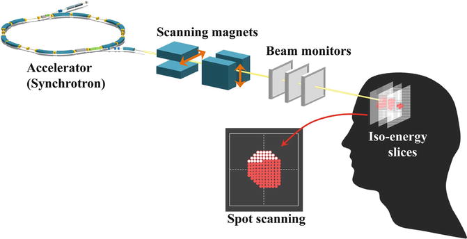
Fig. 4.7
Image view of 3D scanning
There are two approaches for lateral beam scanning, the spot- and raster-scanning methods. In the spot-scanning method, the scan path is quantized into spots and beam is delivered on a spot-by-spot basis. This method is sometimes referred to as a “dose-driven scanning” method since the dose at any given spot is determined fully by the dose delivered at that spot and the beam is turned off after the dose is fully delivered. In this method, the switching speed and precision of beam extraction are crucial, and it is generally difficult to form fine dose distribution with a large number of spots delivered within a tolerable duration. In the raster-scanning method, the pencil beam is delivered continuously during magnetic scanning, which is controlled as a function of the number of particles delivered. This method is a variation of the dose-driven spot-scanning method, in that the beam is not turned off between spots, but the beam that is on, while it is moving from one spot to another, is included in the dose to each spot. This will greatly ease the requirements for the beam extraction system. In treatment planning and beam control, the concept of discrete spots may still be used, but the extra dose delivered in transitions between spots must be mitigated or explicitly counted in plan optimization. Another scheme, which is called “hybrid raster scanning,” was recently developed and has been in practical use [5]. The hybrid raster scanning is essentially same with the dose-driven scanning, but the beam is continually delivered even during the spot position change. During the slice change, on the other hand, the beam delivery is stopped during each slice change.
In the pencil-beam 3D scanning, the beam-utilization efficiency increases to almost 100 %, which is much higher than that of the broad-beam method such as the single beam-wobbling method. The beam intensity is thus estimated to decrease by a factor of 3–5, compared with the broad-beam methods. For scanning beams, however, the dose-rate limitation is determined by considering the following: (1) the quantity of an extra dose due to the finite time to turn off the beam delivery in the spot-scanning method and (2) the amount of extra dose delivered when the beam is moving between positions in the raster-scanning method in which the beam is not turned off. In both cases, the dose is proportional to the beam intensity delivered.
4.3.1.1 Phase-Controlled Rescanning Method (Lateral Scan)
Toward the adaptive cancer radiotherapy for both the static and the moving target, a new 3D scanning technique with a pencil beam was required. NIRS, therefore, proposed phase-controlled rescanning (PCR) with a pencil beam [4]. In the PCR method, as schematically shown in Fig. 4.8, rescanning completes irradiation on one iso-energy slice during one respiratory-gated period. Since the three-dimensional movement of the target is close to “zero” on average, a uniform dose distribution can be obtained even under irradiation on the moving target.

Fig. 4.8
(a) Principle of phase-controlled rescanning (PCR) method and (b) schematic diagram of phase-controlled rescanning (PCR) method
The PCR method requires mainly two technologies: (1) intensity-modulation technique for a constant irradiation time on each iso-energy slice having a different cross section, as shown in Fig. 4.9 and (2) fast pencil-beam scanning technique for completing several-times rescanning within a tolerable time.

Fig. 4.9
Intensity modulation in multiple-energy operation with extended flattop. From upper trace, the exciting current of bending magnets corresponding to the multi-energy operation, the beam spill (the time structure of the extracted beam), the signal of DCCT (DC current transformer) corresponding to the circulating beam intensity and RF-KO signal
1.
Intensity modulation
A spill control system was developed [22] in order to deliver the beam with intensity modulation, based on the improvement of the RF-KO slow extraction method. The core part of this system requires the following functions: (1) calculation and output of an AM signal according to request signals from an irradiation system, (2) real-time processing with a time resolution less than 1 ms, and (3) feed-forward and feedback controls to realize the extracted intensity as requested. This system allows us to control dynamically the beam intensity almost as required.
2.
Get Clinical Tree app for offline access

Fast 3D scanning
For the fast pencil-beam 3D scanning, three key technologies were developed as follows: (1) new treatment planning system (TPS) for the hybrid raster scanning, (2) extended flattop operation of the synchrotron, and (3) high-speed scanning magnet.
1.


New TPS [23]
A new TPS has been developed for fast 3D scanning with a pencil beam. The biological dose distribution of a pencil beam is obtained by combining the measured physical dose distribution and the RBE obtained through measured α and β values in the LQ model. Using the biological dose distribution, the new TPS optimizes the assignment of spot positions and their weights so as to give the prescribed dose on a target and to significantly reduce the dose on surrounding normal tissues. A hybrid raster scanning is employed, instead of spot scanning, in order to save the beam-off period during spot position movement. In the hybrid raster scanning, on the other hand, it is inevitably necessary to deliver an extra dose to the position between the spot positions, which disturbs the dose distribution. It is noted that its disturbance is proportional to the extra dose. As a result, it was not easy to increase the beam intensity delivered to obtain good dose distribution, because the extra dose is proportional to the beam intensity delivered. The HIMAC synchrotron, however, has the high reproducibility and uniformities in the time structure of the extracted beam through the spill control system. One, thus, can predict the extra dose and incorporate its contribution to the treatment planning. Consequently, the beam intensity can be increased without disturbing the dose distribution, which results in the shorter irradiation time. By applying a modified “travelling-salesman problem,” the path length of raster scanning could be shortened by 20–30 %. Finally, the new TPS can increase the scanning speed totally by a factor of about 5.
Related posts:


Stay updated, free articles. Join our Telegram channel
Full access? Get Clinical Tree