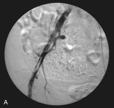
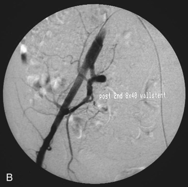
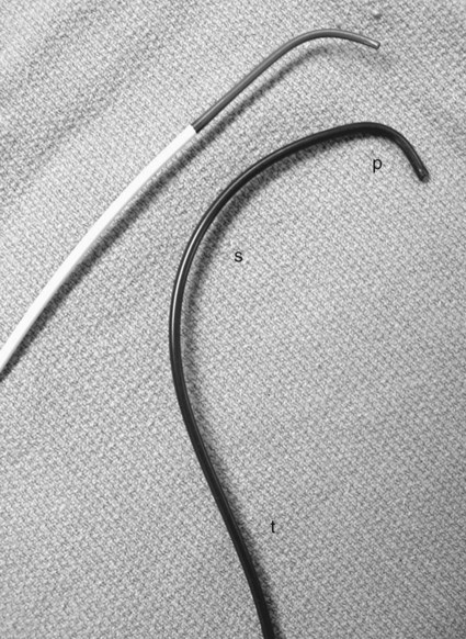
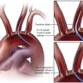
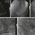
The first percutaneous arteriograms were performed by direct needle puncture of the target vessel. In 1927, Egas Moniz developed the technique for cerebral angiography by direct puncture of the carotid artery; he is considered the father of cerebral angiography.1 Dos Santos and colleagues described a technique for nonselective aortography in which long needles were inserted via the translumbar approach under the guidance of surface anatomic landmarks because fluoroscopy was not yet available.2,3 Early selective angiography was performed via direct cutdown and catheter insertion. The Seldinger technique for femoral access, first reported in 1953, enabled simple and safe flush aortography.4 Seldinger’s U-shaped catheter extended application of his technique to selective catheterization of first-order aortic branches.5 However, the use of long 16-gauge sheathed needles for direct aortic access continued up to the early 1990s for cases in which femoral artery access was unavailable because the high brachial or axillary artery approach was cumbersome and had higher rates of significant complications.6 With the advent of newer 4-French (4F) catheters, brachial artery access became safer, and translumbar aortography soon became obsolete. Needle gauges are derived from wire-gauging standards first used in England during the late 1880s (e.g., Stubbs or Birmingham Iron Wire Gauge system). Needle diameter (inches, estimated) = 1/gauge. Smaller gauges indicate larger diameters. The gauge number (G) always indicates the outer diameter of a needle.7 French (F) size refers to the diameter of a catheter in French units (3F = 0.97 mm = 0.038 inch). Larger French sizes indicate wider catheters. Catheter and dilator sizes are designated by the outer diameter, whereas sheaths are typically designated by their inner lumen size, that is, the maximum catheter diameter capacity (e.g., a 6F sheath accepts a 6F catheter). Typically, the outer diameter of a vascular sheath is 1.5F to 2F larger than the inner lumen. Brachial access from the left (rather than right) side is normally favored. The left-sided approach should produce fewer neurologic complications because the carotid arteries are not in the catheter-wire path; manipulation of the catheter in the descending thoracic and abdominal aorta and its branches is also easier, especially in older patients with ectatic aortic arches. Direct aortic access via translumbar techniques for embolization of endoleaks and for direct vena cava dialysis and catheter placement has revitalized the use of translumbar access needles as interventional rather than diagnostic tools.8,9 The needles are also used to provide transhepatic access for long-term central venous access.10,11 Early arteriography used direct needle puncture techniques for both vascular access and injection. After initial needle placement, the sharp puncture stylet would be removed, and if vigorous arterial flashback was confirmed, the needle hub would be tipped downward to approximate the axis of the artery, and a blunt stylet inserted to advance the needle into the vessel. The needle was subsequently used for nonselective hand injection.12 These blunt obturators are packaged in some contemporary puncture needle kits, a testament to primordial diagnostic angiography. Seldinger’s original technique involves the use of a hollow nonbeveled thin-walled cannula that accepts a sharp stylet for puncture. The classic 18G needle will accept a 0.038 inch guidewire, whereas the 19G needle will allow a 0.035 inch guidewire. Because 18G puncture needles have larger cross-sectional diameters than 4F diagnostic catheters do, they have been supplanted by 19G needles as the standard needle in many interventional radiology suites. The hub end of such needles is typically flanged, which assists in stabilizing it during access. The back end is funneled to direct the guidewire into the trailing portion of the needle. The double-wall puncture is made through the superficial anterior and deeper posterior vessel walls. After the stylet is removed, the needle is pulled back through the deep arterial wall into the lumen; when pulsatile flashback is returned, the guidewire is advanced into the vessel.4 Many interventional radiologists now favor single-wall puncture, a variant of Seldinger’s original technique. Needles used for this technique have a hollow nonstylet needle with a beveled cutting edge; the artery is entered on a forward pass through the anterior arterial wall into the lumen. Although these two techniques are often used interchangeably and according to individual operator preference, specific situations may favor the single-wall technique.13 Posterior wall puncture is generally avoided in patients with coagulopathy or those in whom lysis is planned because it increases the risk of bleeding. Single-wall cutting needles also facilitate access through fibrotic postoperative groins. They are favored by many for femoral venous puncture before dilation for placement of inferior vena cava filters to avoid accidental double puncture of the femoral vein and artery. (The vein may lie partially behind the artery with a low puncture.) As a cautionary note, because the single-wall needle tip is beveled, it can be both luminal and intramural and return pulsatile flow. Advancing the guidewire in this circumstance may initiate subintimal dissection. Dissection can also occur with good luminal position of any needle tip because the firmly held stiff needle cannot back away from a constrained advancing wire tip. Guidewire-related dissections can be difficult to recognize and thus may involve relatively long sections of the punctured artery (Fig. e4-1). Catheters can also be characterized by elements of their engineering: • Shape of the leading segment (tip) • Presence, location, number, and size of side holes • Radiopacity, presence of sizing markers. • Size and use (diagnostic catheter, guiding catheter, microcatheter) The shape of the catheter tip is perhaps its most essential or defining element.13 Aortic flush catheters traditionally include circular or “pigtail” protective tips. Flush catheter designs that produce a more compact bolus than traditional pigtail catheters have been of interest to diagnostic angiographers since the widespread adoption of digital acquisition in the late 1980s.14–16 Variants also include flush catheters with angled shafts that facilitate catheterization of the pulmonary arteries (e.g., “Grollman Pigtail” [Cook, Inc., Bloomington, Ind.]) or catheterization of the iliac artery contralateral to the femoral puncture site (Omni Flush [AngioDynamics, Queensbury, N.Y.]). For selective catheterization of vascular branches of the aorta or vena cava, a variety of more complex shapes are needed because of the large size of the trunk vessel relative to the target vessel origin. Here, selection of the ostium, advancement down the vessel, and positional stability during subsequent manipulation and injection all depend on the wall-seeking behavior of the catheter; it must be in contact with the vessel wall opposite the target branch orifice. It is firm contact with the back wall that turns a catheter potentially flopping in midstream into an efficient device that will engage a branch origin and reorient the relatively vertical pushing force applied at the groin down the axis of the target vessel (Fig. e4-2). For selective catheterization, the two factors that most influence the choice of tip shape are the diameter of the trunk vessel and the angle of origin of the target vessel. The primary curve, closest to the tip, is generally chosen to approximate the takeoff angle of the target vessel. The secondary curve shape is chosen to enable passage of the catheter more peripherally into the target vessel (over the guidewire). Thus, the shape and radius of the combination of curves of a catheter should be chosen to maximize “push-off” from the back wall of the aorta. Some catheter designs use a tertiary curve behind the secondary curve to further enhance wall-seeking ability. Complex catheters in which the primary and secondary curves are in the same direction include the Cobra and Head Hunter families. These catheters can be used right from the package. The Cobra catheter is typically used for catheterization of down-going vessels such as the visceral arteries, but it may not work well if the target vessel is steeply angled. Cobra-type catheters are advanced by pushing and removed by pulling. Waltman and colleagues reported the loop technique for reversing the curve of a braided Cobra catheter to enable catheterization of upgoing vessels such as the left gastric artery.16 Numerous selective catheters have primary and secondary curves of opposite orientation (Fig. e4-3
Diagnostic Catheters and Guidewires
Puncture Needles
Angiographic Catheters
Catheter Shape
Flush Catheter
Selective Catheter
![]()
Stay updated, free articles. Join our Telegram channel

Full access? Get Clinical Tree


Diagnostic Catheters and Guidewires