EYE, ORBIT, VISUAL PATHWAYS, AND CRANIAL NERVES III, IV, AND VI: INTRODUCTION AND GENERAL PRINCIPLES
TECHNICAL ASPECTS
Techniques and Relevant Aspects
Plain films should only be used infrequently for orbital problems. Standard film/screen, digital radiography, or computed radiology techniques are appropriate for the now very infrequent indications for plain radiography.
Ultrasound is generally performed with an 8- to 10-MHz transducer. Either A mode or B mode, color flow, and power Doppler techniques are used depending on specific indications. These examinations are usually performed by ophthalmologists. They are used to evaluate both intraocular and orbital pathology. Other imaging methods frequently used by ophthalmologists to evaluate ocular structures and pathology are autofluorescence, fluorescein angiography, and optical coherence tomography (OCT). Autofluorescence is based upon the naturally occurring fluorescent emission of ocular tissues and is used to evaluate retinal diseases and vascular abnormalities. To examine the circulation of the retina, fluorescein angiography is used: After injection of sodium fluorescein into the systemic circulation, the fluorescence emitted after illumination of the retina is recorded. By use of this method, diabetic retinopathy, vascular occlusions, edema of the optic disc, and tumors can be detected. OCT is a noninvasive imaging technique with millimeter penetration and submicron resolution producing high-resolution cross-sectional images of optical reflectivity. Topographic maps can be obtained. The images are displayed in a color scheme. OCT is particularly suitable to examine retinal thickness.
Specific computed tomography (CT) techniques by indications are detailed in Appendix A. In the past, gantry angulation may have been changed from the usual zero degrees to the infraorbital meatal line (IOML) to –10 degrees for emphasis on the course of the optic nerve toward and then through the optic canal. Such angling is really not necessary with ≥16 slice multidetector computed tomography (MDCT) and workstation viewing since slightly off-axial axis reformations done at the workstation from the axial data set are not significantly degraded. Acquisition slice thickness (SLT) should be ≤0.5 to 1.0 mm. Reformations will be of excellent quality with such data acquisition.
Intravenous contrast is used frequently. If calcifications are important to the detection of pathology and/or differential diagnosis, a noncontrast acquisition should be done. That decision should be made on a case-by-case basis to avoid a radiation dose to the lens. This is typically only done in practice for the initial evaluation of a child with possible retinoblastoma. Non–contrast enhanced CT is also done initially to rule out an intraorbital foreign body. Magnetic resonance imaging (MRI) can also be useful for foreign bodies if they are composed of plant or similar organic material.
Scanning with and without a Valsalva maneuver, with the orbit in different dependent positions, or with venous compression may be very useful in the rare cases of suspected orbital varices.1
Specific magnetic resonance (MR) protocols are outlined in Appendix B. MR examinations of the orbit are routinely done with a localized volume receiver coil that allows for visualization of both orbits and surrounding structures of interest such as the paranasal sinuses. A localized surface coil may be useful for higher-resolution studies of ocular or single orbit pathology that does not require visualization of more posterior structures. A standard volume head coil is used for studies of the visual pathways.
SLT should be ≤3 mm. A field of view of 8 to 10 cm with a localized receiver coil if only the eye is studied and 12 to 16 cm if the entire orbital area on both sides must be included as a region of interest.
All eye makeup, especially mascara and shadow, should be removed for MR studies. The head should be positioned so that the IOML is perpendicular to the tabletop; the head may be tilted back in a “chin up” position 10 degrees if the optic nerve and canal are of primary interest. Alternatively, a quick view can be done to choose the optimal plane. Oblique sagittal acquisitions in the plane of the optic nerve are occasionally useful for studying the optic nerve. Standard two-dimensional Fourier transform (2DFT), spin echo (SE) techniques are usually used; fast spin echo (FSE) sequences are used for T2-weighted images. Fat-nulling short TI inversion recovery (STIR) or true fat suppression pulse sequences are included to evaluate the orbit. Currently, frequency selective fat suppression is the most common fat suppression method employed. This suffers from sometimes critical susceptibility artifacts at the margins of the orbits and surrounding air-filled sinuses as well as along the course of the second through sixth cranial nerves as they lie along a well-aerated sphenoid sinus. This significant problem is discussed in Chapters 1 and 3 (Fig. 1.4). This problem is magnified at 3 Tesla (T). Fat suppression is, however, uniformly superb in the midportion of the muscle cone for evaluation of pathologic changes involving the optic nerve and sheath and surrounding intraconal fat.
Another artifact encountered frequently in orbital MRI is chemical shift or water–fat shift (WFS). The artifact increases the higher the field strength. The WFS decreases with higher receiver bandwidth; however, this occurs at the expense of signal-to-noise ratio (Figs. 3.2 and 44.1). Although WFS will still be present, fat suppression techniques will render the WFS artifact invisible.
Imaging of the eye and orbit is also susceptible to motion artifacts, causing blurring and signal throughout the object and the background, most pronounced in the phase-encoding direction. Whereas a frequency-encoding step is acquired in the time of a single echo, this taking a few milliseconds, a phase-encoding step requires collection of all lines of k-space, each separated by repetition time that takes minutes. This explains why motion artifacts along the frequency-encoding direction are usually insignificant.
Intravenous paramagnetic contrast is used frequently. Magnetic resonance angiography (MRA) is used most frequently for lesions of the cavernous sinus region or suspected cases of intracranial aneurysms and those of the ophthalmic artery or posterior communicating artery aneurysms in particular. MRA is usually done with a time of flight technique optimized for spatial resolution and background suppression; the technical aspects of this were detailed in Chapters 1 and 3.
Much diagnostic angiography in this anatomic region area is done by computed tomographic angiography (CTA) or MRA. Such studies should be done with as high a resolution technique as possible. In general, CTA should be done with 0.5- to 1.0-mm–thick sections. Bone subtraction CTA for this area, which is so intimately related to the central skull base, may prove more definitive than standard postprocessing techniques segmenting out bone from vessels. MRA of definitive quality is usually not possible on units operating under 1 T, but lower field units may produce studies sufficient for gross screening in selected circumstances.
Catheter angiography is reserved as a prelude to endovascular therapy and in high flow lesions and or when the smaller vessel angioarchitecture is important in medical decision making. The later indications likely will diminish with the recent advent of 320 MDCT or its equivalent.

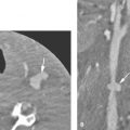
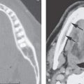
FIGURE 44.1. Artifacts as seen on magnetic resonance imaging of the orbit. A, B: The field distortion artifacts seen along the floor of the orbit (arrows in A) become much exaggerated in the fat suppression image (arrows in B). The field distortion artifacts that are much worse in (B) also obscure the anatomy at the orbital apex (arrowheads). C: Field distortion artifacts due to permanently placed eyeliner as a tattoo. D: Water–fat shift artifact (arrows).
Dacryocystography is performed in patients with functional nasolacrimal duct obstruction, usually presenting with epiphora. First, a local anesthetic is dropped into the conjunctival sac. Next, a lacrimal cannula is introduced into the lower punctum. If necessary, a punctum dilator can be used to facilitate insertion of the cannula. The cannula is fixed by taping. During imaging, 1 to 2 mL of water-soluble contrast medium is injected. An oil-based contrast medium should be avoided, as complications such as granuloma formation may occur after extravasation.2,3
PROS AND CONS
MR has assumed a primary role for much of the imaging of the orbit and visual pathways. Its sensitivity to intra-axial pathologies is especially valuable in this region. Its lack of sensitivity to calcification, suboptimal depiction of bone detail, and occasional difficulties with motion degradation compared with CT need to be balanced against its strengths in individual cases. Some factors for triage of patients to CT rather than MR are suggested in the following paragraphs.
General indications for MR and CT may be divided into those primarily aimed at the eye, orbit, visual pathways, and cavernous sinuses (Appendixes A and B). For the eye, ultrasound may be the only diagnostic imaging examination needed, although MR and CT can be used adjunctively or as a first choice depending on the clinical situation. Since the late 1980s, color flow Doppler techniques have further increased the utility of ultrasound as a primary diagnostic tool.4 The main limitations of MR in evaluating the eye are its sensitivity to motion artifact and insensitivity to calcification.
Imaging of the orbit, periorbital soft tissues, cavernous sinuses, and surrounding structures, which may give rise to orbital pathology, is done for many indications. Triage of patients to MR or CT is often a matter of preference or availability of services. CT is preferred for inflammatory disease because of its potentially clearer depiction of a fluid collection, the nature of surrounding inflammatory reaction, and bone detail. In trauma, if bone detail or foreign body detection is most important, CT is also preferred with few exceptions, which are discussed in Chapter 51 on ocular trauma. Contrast-enhanced and plain CT offer limited advantages over MR for most mass lesions; thus, MR is a reasonable first choice, while remembering that the presence of calcifications or subtle bone destruction may go unnoticed on MR. MR can be used for diagnosing endocrine ophthalmopathy, but noncontrast CT is a less expensive alternative.
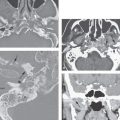
Disorders of the optic pathways should almost always be studied with MR. MR displays the entire visual pathway, including the optic nerve, chiasm, and tracts as well as the lateral geniculate body, optic radiations, visual cortex, cavernous sinus, and brain stem (Fig. 44.2). On less highly spatially resolved MR studies, the exclusion of an optic sheath meningioma may still prove troublesome; however, contrast-enhanced MR with fat suppression pulse techniques can overcome this problem.5 CT may be the best choice for detecting subtle optic sheath lesions if high-resolution fat-suppressed MR is not available. MR is the preferred examination for evaluating the cavernous sinus and orbital apex. Most of the individual cranial nerves related to the cavernous sinus are visible on high-resolution MR studies, and at least a screening study of the carotid artery and its branches is possible as well with MRA. MR is also more sensitive than CT to dural and leptomeningeal pathology that involves the cavernous sinus, suprasellar cistern, and optic nerve/sheath complex. CT is used adjunctively to study bone detail or when MR is not possible or definitive.
Dacryocystography is performed in patients with functional nasolacrimal duct obstruction, usually presenting with epiphora after imaging has shown no obvious obstructing mass lesions.
Controversies
Few real controversies exist with regard to imaging of this anatomic region. The choice between CT and MRI as a starting point for a given diagnostic probably are fairly well defined. Ultrasound is a tool essentially of the ophthalmologist, and few diagnostic radiologists perform or interpret these examinations. It is possible that these studies are sometimes superfluous, especially if one already knows that CT or MRI will be performed later in the diagnostic process. Ultrasound examinations, in experienced hands and in the correct clinical context, have the capacity to eliminate the need for CT and/or MRI with the resulting benefits of cost reduction and no radiation exposure.
MRA may be used to depict the relationship of pathologies to the ophthalmic artery as well as the cavernous portion of the carotid artery and its cerebral branches. MRA may also be used to screen for aneurysms; however, CTA in combination with conventional angiography remains the approach of choice for this indication. MRA is an excellent means for detecting carotid artery dissection and cavernous-carotid and other fistulae, but conventional angiography may still be necessary to completely evaluate these pathologies and as an aid to planning endovascular therapy when angioarchitecture and flow dynamics are required data.6 The later indications likely will diminish with the recent advent of 320 MDCT or its equivalent.
NORMAL ANATOMY
General Anatomic Description
The eye and related visual pathways constitute one of our most important special senses. The eye is housed in a protective and functional bony compartment—the orbit. The general relationships of the orbital contents and bony orbit are presented in Figures 44.2–44.11. It is connected centrally by the optic nerve, which in reality is a tract of the brain projecting to the eye. These structures constitute the anterior visual pathways (Fig. 44.2). These are covered and further protected by the preseptal soft tissues that are in turn highly integrated with the lacrimal production and drainage system.
The posterior visual pathways begin where the optic tracts synapse with the lateral geniculate body continuing through the brain as the optic radiations to the primary visual cortex. There are many other connections of the visual system within the brain that are beyond the scope of this text.
The ocular motor system begins with the six extraocular muscles in the orbit and becomes primarily integrated with the rest of the brain within the brain stem by cranial nerves II, IV, and VI as well as the cervical sympathetics. There is a convergence of all of the extraocular muscles and ocular motor cranial nerves at the orbital apex and the adjacent cavernous sinus and paracavernous regions with their related cisterns and other surrounding cerebrospinal fluid–containing spaces.
These general functional anatomic units form the basis for the organization of the following anatomic discussion and much of the organization of the pathologies that involve the visual pathways.

FIGURE 44.2. Schematic diagram of visual pathways from the eye to the visual cortex.

FIGURE 44.3. Schematic diagrams of orbital anatomy to correlate with images in Figures 44.4, 44.5, and 44.6.


FIGURE 44.4. Axial contrast-enhanced T1-weighted magnetic resonance images to compare with the anatomic diagram in Figure 44.3.


FIGURE 44.5. Contrast-enhanced computed tomography images to correlate with the anatomic diagram in Figure 44.3.


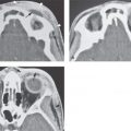
FIGURE 44.6. Bone window computed tomography images to correlate with schematic diagram of orbital anatomy in Figure 44.3.

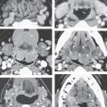
FIGURE 44.7. Schematic diagram showing structures as seen in the coronal images in Figures 44.8, 44.9, and 44.10.

FIGURE 44.8. A–F: Non–contrast-enhanced T1-weighted images of the orbit to correlate with the anatomic diagram in Figure 44.7.
Detailed Description of Specific Areas
Osteology
The orbit is a complex structure composed from portions of seven facial bones (Figs. 44.3–44.11). In simple terms, the orbit may be considered a cone; its entrance—the orbital rim—is formed by thick cortical bone with a single opening, while its cranial end—the orbital apex—is formed by bone of variable thickness with multiple openings. The intraorbital surfaces include a floor, medial and lateral walls, and a roof (Fig. 4.11).
The orbital floor, made up primarily of the maxilla and to a lesser extent the zygoma, is also the roof of the maxillary sinus. The infraorbital groove and canal lies at the junction of the middle and lateral thirds of the orbital floor and contains the infraorbital neurovascular bundle. The orbital floor ends centrally at the inferior orbital fissure. Fat fills the inferior orbital fissure, which lies just above the pterygopalatine fossa. The foramen rotundum lies in a coronal plane just posterior to the fissure and fossa. A small portion of the medial floor is formed by the palatine bone.
The lateral orbital wall is formed posteriorly by the greater wing of the sphenoid and anteriorly by portions of the zygoma (Figs. 44.3–44.11). A small vascular foramen containing an anastomosis between the anterior deep temporal artery and the lacrimal branch of the ophthalmic artery penetrates the lateral wall. The greater wing of the sphenoid is the lateral boundary of the superior orbital fissure; the fissure is a passageway for several important neurovascular structures discussed subsequently.7,8


FIGURE 44.9. Contrast-enhanced computed tomography images to correlate with anatomy as shown in Figure 44.7.


FIGURE 44.10. Contrast-enhanced T1-weighted fat-suppressed images in (A, C, E) and fat-suppressed T2-weighted images in (B, D, F) to correlate with anatomy as seen in Figure 44.7.


FIGURE 44.11. A–D: Anatomic diagrams demonstrating osteology of the orbit and related skull base. (continued)
The orbital roof is mainly formed by the frontal bone. The lesser wing of the sphenoid completes it posteriorly. The supraorbital foramen or notch contains the supraorbital neurovascular bundle (V1) and is found at the junction of the inner and middle thirds of the orbital rim (Fig. 21.51A). The supratrochlear neurovascular bundle exits more medially, between the supraorbital notch and trochlea (Figs. 44.12 and 21.51B). The lateral orbital wall and orbital roof combine to fix the lateral aspect of the face to the midface. The orbital floor is not continuous with the skull because of the interposed inferior orbital fissure.
The medial orbital wall anatomy is complex. Anteriorly, it is formed by the lacrimal bone, whose orbital surface presents as a central depression between the anterior and posterior lacrimal crests (Figs. 44.3–44.11). The lacrimal sac fits into this depression and connects to the lacrimal duct, which descends in the nasolacrimal canal to open under the inferior turbinate (Fig. 44.13). The medial palpebral ligament connects the tarsal plates of the eyelids with the anterior lacrimal crest. The lateral palpebral ligament is attached to the lateral orbital rim. The midportion of the medial orbital wall—the orbital plate of the ethmoid—is thin cortical bone called the lamina papyracea. The posterior aspect of the medial wall is formed by the body of the sphenoid bone. The remainder of the orbital apex is also fashioned from portions of the sphenoid bone. The optic canal passes obliquely beneath the lesser wing of the sphenoid; the optic strut creates its lateral margin. The optic strut separates the optic canal from the remainder of the superior orbital fissure.7,8

FIGURE 44.12. Contrast-enhanced T1-weighted image showing the relationship of the supraorbital notch (arrow) lying beneath the superficial musculoaponeurotic system of the face. The supraorbital and supratrochlear vessels can be seen (arrowheads).
Eye
The multilayered eyeball includes the retina, the intermediate uveal tract, and the outer sclera/cornea (Figs. 44.2 and 44.14). The photosensitive neural layer of the retina anchors posteriorly at the optic nerve head and anteriorly at the ora serrata; the latter lies just proximal to the ciliary body. The pigmented layer of the retina continues into the iris, while the neural layer does not. The retina is separated from the posterior vitreous membrane by the potential subhyaloid space (Figs. 44.14 and 44.15). The posterior vitreous body is not purely fluid but rather is transparent water-containing gel filling an interstitial cellular meshwork. The vitreous body is normally of fluid-equivalent signal intensity on T1- and T2-weighted images (Fig. 44.15). It is this interstitial tissue that forms a vitreous scar in response to a variety of injuries such as neonatal hyperoxygenation, retinal inflammation, and hemorrhage. The lens attaches to the ciliary body by the zonular fibers, separating the anterior chamber and anterior vitreous from the posterior chamber and posterior vitreous (Figs. 44.14 and 44.15). The lens fibers are oriented circumferentially into two portions: a central nucleus and outer cortex. The lens is usually hyperintense to the vitreous body on T1-weighted images and hypointense to it on T2-weighted images.


FIGURE 44.13. Various studies and anatomic diagrams of lacrimal system. A: Anatomic diagram showing the relationship of the lacrimal gland to the conjunctival sac and the lacrimal drainage apparatus. B, C: Views from a dacryocystogram. In (B), the inferior canaliculus is cannulated, and both the superior and inferior canaliculi are filled (black arrows). The common canaliculus is filled (arrowhead) with contrast to the junction of the lacrimal sac and nasolacrimal duct (white arrow). D: The nasolacrimal duct (arrow) drains beneath the inferior turbinate (arrowhead). E: Oblique view of a computed tomography study to show the course of the lacrimal canal from its position in the medial floor of the orbit (arrow) to its drainage under the inferior turbinate (arrowhead). F: Sagittal reformation showing the same anatomy as just discussed in Figure 44.13D.

FIGURE 44.14. Anatomic diagram of the layers and other internal structure of the eye and its junction with the optic nerve and sheath.
The central space present during the formation of the optic vesicle initially separates the photosensitive inner layer from the pigmented outer layer of the retina. Although this space is resorbed, the apposition of the two retinal layers is tenuous. In fact, the outer pigmented layer becomes more tightly bound to the Bruch membrane, the inner most layer of choroid, and the other choroidal layers than it does to the neural layer.
It is in this potential space, between the pigmented and neural retinal layer, that subretinal effusions can accumulate and produce retinal detachment (Chapter 45).
The uveal tract is composed of the highly vascular choroid, the ciliary body, and the iris. The entire uveal tract is seen on good-quality, contrast-enhanced MRI (Fig. 44.15). The ciliary body contains the muscles required for accommodation control. The vascular layer of the choroid is composed of circumferential vascular plexuses. The endothelium of choroidal capillaries is fenestrated similar to gastrointestinal endothelium. Nutrients freely diffuse from the choroid across the Bruch membrane to supply the pigmented layer of the retina. The efferent choroidal vessels collect in bulbar vorticose veins, which penetrate the sclera and drain into the superior and inferior ophthalmic veins (Fig. 44.16). As they penetrate the sclera, these choroidal emissary veins along with the ciliary arteries tether the choroid, which limits the extent of fluid accumulation in suprachoroidal effusions and detachments. This provides an anatomic means of differentiating at least some suprachoroidal from subretinal detachments on imaging studies.

FIGURE 44.15. Contrast-enhanced T1-weighted fat-suppressed images showing enhancement of the normal uveal tract. A: Both enhancement of the ciliary body (arrowhead) and choroid (white arrow) is commonly visible. On the opposite side, the junction of the optic nerve (optic disc) and eye is typically flat and does not enhance (black arrow). B: Axial T2-weighted image shows the optic nerve (arrow) within the optic sheath surrounded by cerebrospinal fluid. The subarachnoid space is still visible within the optic canal (white arrowhead). The continuation of the optic nerve to the junction of the optic nerve and chiasm (black arrow) and then the optic tract (black arrowhead) completes the anterior visual pathway.
Related posts:
 Preseptal Compartment: Acute and Chronic Infections and Noninfectious Inflammatory Conditions
 Necrotizing (“Malignant”) Otitis Externa
 Cervicothoracic Junction: Brachial Plexus Trauma
 Oropharynx: Introduction
 Branchial Apparatus Developmental Anomalies
 Oral Cavity and Floor of the Mouth: Malignant Tumors
Stay updated, free articles. Join our Telegram channel

Full access? Get Clinical Tree


