Clinical Presentation
The patient is a 52-year-old male who was the driver of a jet ski on a private lake over the 4th of July weekend. Observers say that he was driving approximately 40 miles per hour when another boat pulling children on a tube crossed in front of him. The patient swerved so as not to hit the children, and he slammed head on into a boat dock. The patient was brought unconscious to the emergency department.
Imaging Presentation
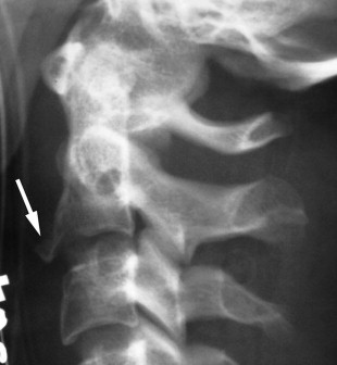
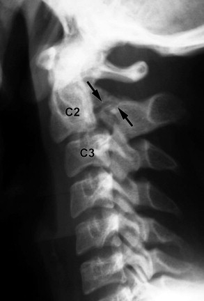
Lateral radiograph and axial computed tomography (CT) images reveal fractures through the C2 pedicles with anterior displacement of C2 with respect to C3 consistent with a traumatic spondylolisthesis, also known as a Hangman’s fracture . There are bone fragments in the region of the left vertebral artery foramen, which should be considered if there is suspicion of traumatic injury to the left vertebral artery ( Figs. 37-1 and 37-2 ) .

Discussion
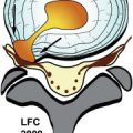
The first cervical fracture-dislocation injury caused by hanging was described in 1913. The term traumatic spondylolisthesis of the axis was described in 1964 in patients with fractures of the C2 pedicles after motor vehicle accidents. The term hangman’s fracture was attributed to Schneider, who in 1965 described the similarity of judicial hanging fractures to traumatic fractures of the axis. The mechanism of a hanging fracture is one of distraction and hyperextension. Today’s hangman’s fractures are typically deceleration injuries caused by motor vehicle accidents, diving, and falls in which the mechanism of injury is vertical compression and hyperextension, which causes the neural arch of C2 to be separated from the C2 vertebral body. Head injuries are highly associated with this type of hangman’s fracture. The odontoid process remains intact. Fractures of the ring of the axis can occur through several areas of C2 including the laminae, pedicles, superior or inferior articular facets, pars interarticularis, and posterior wall of the vertebral body ( Fig. 37-3 ) . The fractures are often bilateral but not symmetric.

Hangman’s fractures can be classified into three types based on their displacement and mechanism of injury. In type 1 injury (axial loading and hyperextension), the C2 vertebral body is nonangulated. The C2 body may be nondisplaced or minimally displaced (less than 2-3 mm) with a normal C2-3 intervertebral disc. In type 2 injuries, the C2 vertebral body is anteriorly displaced or angulated and there is disruption of the C2-3 disc. In type 3 injuries (primary flexion and rebound extension), there is anterior displacement and hyperflexion of the C2 vertebral body along with unilateral or bilateral facet dislocation. Type 2 has been subdivided into type 2 and type 2a. This distinction is important because their mechanisms of injury are different and therefore their treatments are different. Type 2 fractures result from hyperextension and rebound flexion and type 2a is a flexion distraction injury. Hangman’s fractures are typically treated with traction; however, treating a type 2a fracture with traction will lead to further distraction of the injury.
Type 1 fractures are the most common (65%), followed by type 2 (28%), and type 3 (7%). Type 1 fractures are considered stable. Types 2, 2a, and 3 are unstable fractures. In one study of all types of cervical fractures, 19% were fractures of the axis, with 4% being the hangman’s type. The incidence of spinal cord and nerve root injury is reported to be low, which may be related to the relatively spacious intracanalicular diameter at C2, which affords some protection against spinal cord compression. However, the risk to the spinal cord increases with the severity of the fracture.
Patients who sustain a hangman’s fracture typically present with acute neck pain after a traumatic incident. Most patients do not have neurologic symptoms; however, neurologic symptoms can occur and depend on which part of the spinal cord is affected. Patients may also have delayed stroke if there has been damage to the vertebral artery.
Other fractures of the cervical spine that are important to recognize are odontoid fractures, Jefferson fracture, extension teardrop fractures, hyperextension dislocation fractures, flexion teardrop fractures, and clay shoveler’s fractures.
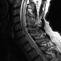
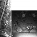
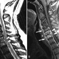
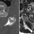
There are three classifications of odontoid fractures . A type 1 fracture is an infrequent, stable fracture of the tip of the odontoid process. A type 2 fracture is an unstable fracture through the base of the odontoid process ( Fig. 37-4 ) . A type 3 fracture is a stable fracture that passes through a portion of the superior body of C2 ( Fig. 37-5 ) . Type 2 fractures are the most common, occurring in 31% to 65% of cases, and are complicated by nonunion in 26% to 36% of cases. Odontoid fractures, being in an axial plane, are best visualized in the coronal or sagittal plane either directly with magnetic resonance (MR) imaging or with reformatted computed tomography (CT) imaging, but can be visualized with plain radiographs as well. MRI can be used to evaluate the chronicity of the fracture. A recent fracture will demonstrate increased signal intensity on fat-saturated, T2-weighted or short tau inversion recovery (STIR) acquisitions and increased prevertebral soft tissue signal. A type 1 fracture can have an appearance similar to an os odontoideum (unfused ossification center cephalad to the dens). A type 1 fracture will have irregular noncorticated borders as opposed to the well-corticated periphery of an os odontoideum.
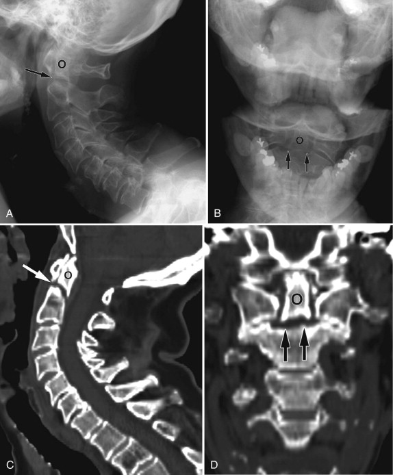

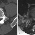
The Jefferson fracture is an axial loading compression fracture of the lateral masses of the atlas between the occipital condyles and articular facets of C2. The lateral masses are driven laterally away from C2 by the compressive force, which results in fractures of the anterior and posterior ring of C1. The fractures may be unilateral or bilateral and can consist of 2 to 4 fragments. Jefferson fractures are typically stable with an intact transverse ligament. The separation of the lateral masses can be seen with open-mouth plain radiographs of the craniocervical junction. The more definitive diagnosis is best identified with axial CT with coronal reformatted images demonstrating noncorticated fracture lines and prevertebral soft tissue edema ( Fig. 37-6 ) . However, one should not mistake a fracture with a congenital developmental cleft, which has well-corticated margins and no associated soft tissue edema.

Extension teardrop fractures occur frequently and represent 19% of all fractures of C2. This fracture is due to avulsion of the anterior longitudinal ligament with a triangular piece of bone from the anterior inferior vertebral body ( Fig. 37-7 ) . One important characteristic of the fracture fragment is that its vertical height is either equal to or greater than its transverse dimension. This distinguishes an extension teardrop fracture from the similarly appearing hyperextension dislocation injury. Furthermore, patients with extension teardrop fractures typically do not have any neurologic symptoms, unlike those with hyperextension dislocation.

