Mohini Rawat, DPT, MS, ECS, OCS, RMSK
Contents
- Anterior Hip
- Joint Anatomy
- Iliopsoas Tendon
- Tendons Originating From the Anterior Superior Iliac Spine
- Tendons Originating From the Anterior Inferior Iliac Spine
- Joint Anatomy
- Lateral Hip
- Posterior Hip
- Piriformis and Sciatic Nerve
- Other Small Rotators of the Hip
- Hamstring Tendon Origin at the Ischial Tuberosity
- Piriformis and Sciatic Nerve
- Inguinal and Medial Hip Regions
- Patient position: Supine with the hip in extension and slight abduction
- Probe/transducer position: The probe is along the long axis (LX) of the femur anteriorly at the level of greater trochanter (but not placed on the lateral aspect over the greater trochanter), and then the probe is rotated medially toward the midline and moved proximally to be along the LX of the femoroacetabular joint (Figures 7-1 through 7-3).
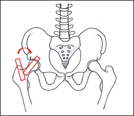
Figure 7-1. Probe positioning for the LX view of the femoroacetabular joint.
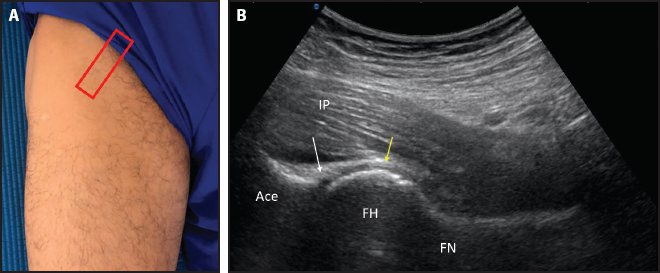
Figure 7-2. LX view of the hip joint. (A) Probe placement. (B) LX view of the hip joint showing the acetabulum (Ace), femoral head (FH), femoral neck (FN), iliopsoas muscle-tendon complex (IP), hyperechoic labrum (white arrow), and hyperechoic capsuloligamentous layer (yellow arrow).
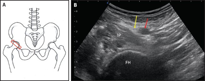
Figure 7-3. Short axis (SX) view of the hip joint. (A) Probe placement. (B) SX view of the hip joint showing the femoral head (FH), iliopsoas muscle-tendon complex (IP), hyperechoic femoral nerve (yellow arrow), and anechoic femoral artery (red arrow).
- Relevant anatomy: The acetabulum, labrum, and femoral head and neck are visualized.1 The capsuloligamentous structure follows the bony contour of the head and neck of the femur.2
- Points to remember: The joint is evaluated for excess fluid, capsular thickening, synovial hypertrophy, labral pathology (limited view), loose bodies, or bony irregularity or erosion, or to study the soft tissue structures overlying the joint like the iliopsoas bursa and iliopsoas muscle-tendon complex. Femoroacetabular impingement is suspected with the following changes in the anterior hip joint: presence of nonspherical head neck junction (cam deformity), focal bony protuberance at the femoral neck, or waist deficiency or convexity at the femoral head-neck junction (Figure 7-4).3
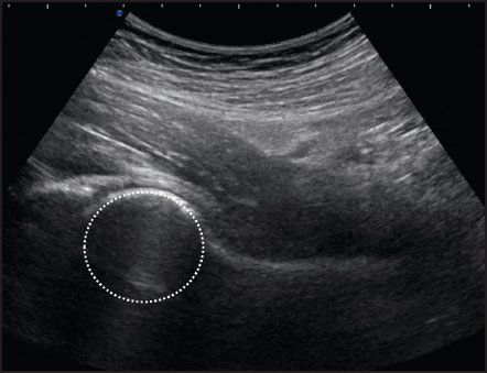
Figure 7-4. The femoral head is normally spherical. Femoroacetabular impingement is suspected with the following changes in the anterior hip joint: presence of nonspherical head-neck junction (cam deformity), focal bony protuberance at the femoral neck, or waist deficiency or convexity at the femoral head-neck junction.
- Relevant anatomy: The acetabulum, labrum, and femoral head and neck are visualized.1 The capsuloligamentous structure follows the bony contour of the head and neck of the femur.2
- Patient position: Supine using the flexion, abduction, and external rotation (FABER) maneuver, where the patient is asked to place the lateral aspect of the foot on the side to be studied on the contralateral knee at the suprapatellar region4
- Probe/transducer position: The probe is initially placed along the LX of the femoral head to identify the iliopsoas tendon overlying the joint, then the iliopsoas tendon is followed to its insertion site at the lesser trochanter (Figures 7-5 and 7-6).
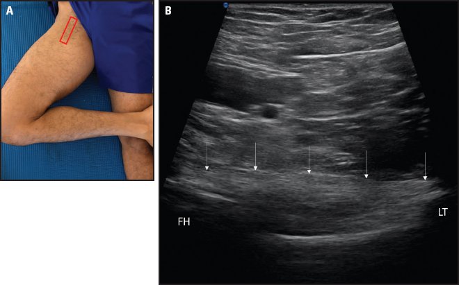
Figure 7-5. LX view of the iliopsoas tendon. (A) Probe placement with the patient supine using the FABER maneuver. The probe is initially placed along the LX of the femoral head to identify the iliopsoas tendon overlying the joint, then the iliopsoas tendon is followed to its insertion site at the lesser trochanter. (B) LX view of the hyperechoic iliopsoas tendon (white arrows). (FH = femoral head; LT = lesser trochanter.)
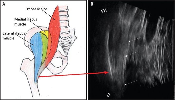
Figure 7-6. (A) Relevant anatomy of the iliopsoas muscle-tendon complex. (B) Corresponding LX view of the iliopsoas tendon (white arrows) inserting on the lesser trochanter (LT). (FH = femoral head.)
- Relevant anatomy: The main tendon in the distal iliopsoas is the psoas tendon, including fibers from the medial portion of the iliacus. The lateral iliacus muscle runs parallel to the iliopsoas tendon and attaches directly onto the proximal femoral shaft (Figures 7-7 and 7-8).5,6
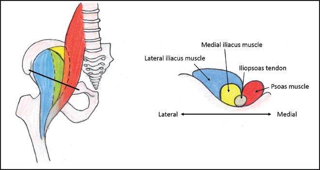
Figure 7-7. Relevant cross-sectional anatomy of the iliopsoas muscle-tendon complex at the level of the iliopectineal eminence.
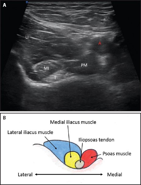
Figure 7-8. (A) SX view of the iliopsoas muscle-tendon complex at the level of the iliopectineal eminence showing the lateral iliacus muscle (LI), medial iliacus muscle (MI), tendon (T), psoas muscle (PM), and femoral artery (red A). (B) Relevant anatomy
- Points to remember: The most medial fibers of the iliacus form an accessory tendon that merges with the psoas tendon to form the main tendon. There is a fatty fascial plane that separates the distal iliopsoas tendon from the intramuscular tendon within the lateral portion of the iliacus muscle, which should not be confused with a split tear of the iliopsoas muscle-tendon complex.5
- Relevant anatomy: The main tendon in the distal iliopsoas is the psoas tendon, including fibers from the medial portion of the iliacus. The lateral iliacus muscle runs parallel to the iliopsoas tendon and attaches directly onto the proximal femoral shaft (Figures 7-7 and 7-8).5,6
Tendons Originating From the Anterior Superior Iliac Spine
Anatomy of the anterior superior iliac spine (ASIS) and surrounding iliac crest region is shown in Figures 7-9 and 7-10.
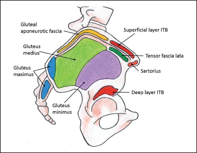
Figure 7-9. Relevant anatomy showing the footprints of various structures originating from the ASIS, iliac crest, and ilium. (ITB = iliotibial band.)
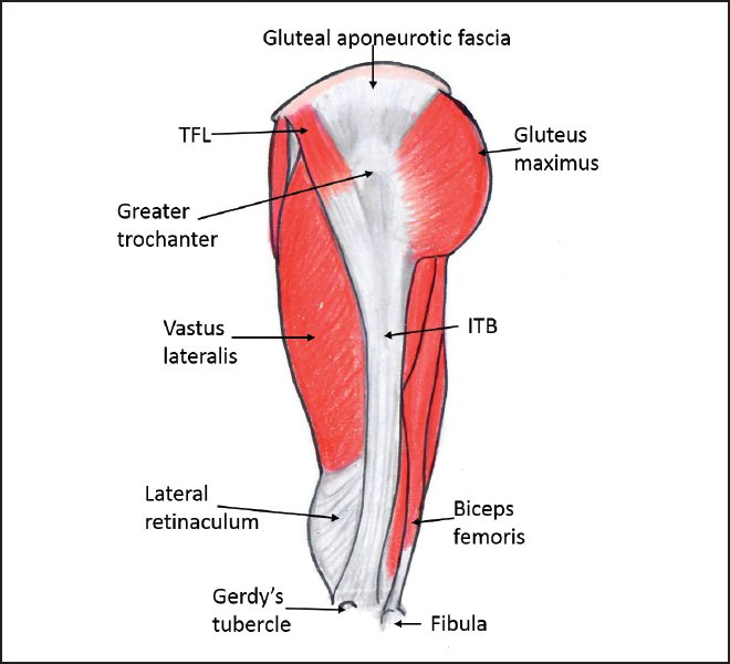
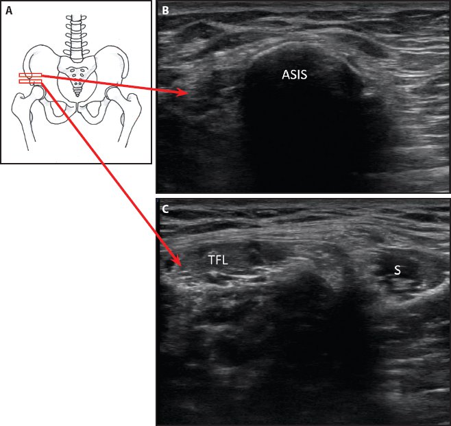
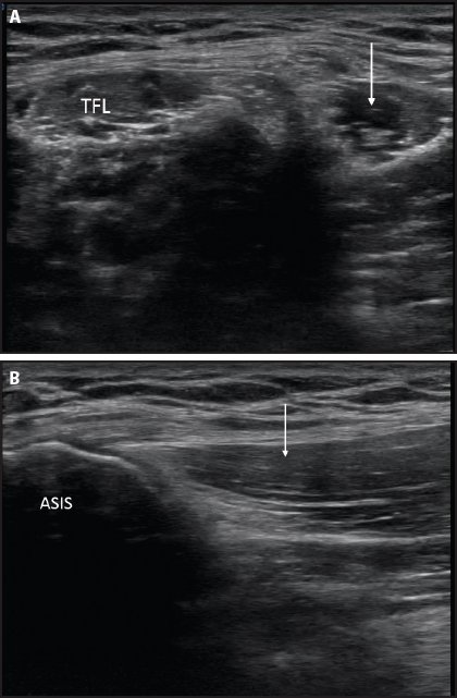
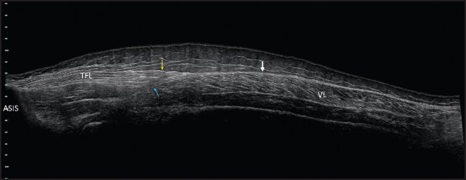
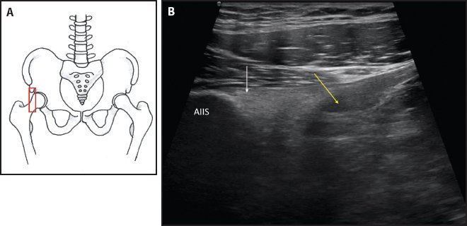
Figure 7-10. Relevant anatomy of the iliotibial band and lateral thigh muscles. (ITB = iliotibial band; TFL = tensor fascia lata.) Figure 7-11. SX view of the sartorius and tensor fascia lata. (A) Probe placement. First the probe is placed on the ASIS and then moved slightly distal to visualize the sartorius medially and the tensor fascia lata laterally. (B) SX view at the ASIS. (C) SX view at the level just distal to the ASIS showing the sartorius (S) medially and the tensor fascia lata (TFL) laterally. Figure 7-12. (A) SX view of the sartorius (white arrow). (TFL = tensor fascia lata.) (B) LX view of the sartorius (white arrow). Figure 7-13. Panoramic view of the anterolateral thigh showing the tensor fascia lata (TFL), superficial layer of the iliotibial band (yellow arrow), deep layer of iliotibial band (blue arrow), and common iliotibial band distally (white arrow). (VL = vastus lateralis.) Tendons Originating From the Anterior Inferior Iliac Spine Figure 7-14. LX view of the rector femoris. (A) Probe placement. (B) Hyperechoic rectus femoris direct head (white arrow) attaching to the AIIS. The indirect head (yellow arrow) appears hypoechoic due to anisotropy as the tendon attaches to the superolateral margin of the acetabulum.
Stay updated, free articles. Join our Telegram channel

Full access? Get Clinical Tree


