Surgical procedures in the oral cavity and maxillofacial complex are diverse and involve multiple tissues unique to this region. These procedures are used to remove pathology and infection, restore function, optimize occlusal relationships, prosthetically replace teeth and temporomandibular joints, improve esthetics, and increase upper respiratory tract dimensions. Procedures in the oral cavity are often complicated by infection stemming from the naturally occurring oral flora, but can also be complicated iatrogenically. This article explores the more commonly encountered surgical procedures through examination of the indications, anatomy to consider, and the radiographic imaging of success and failure of these procedures.
Key points
- •
Preoperative imaging is important for determining the extent of a lesion and the normal anatomic configuration of the structures.
- •
Obtaining a baseline image immediately postoperatively is crucial for evaluation of progress and recurrence.
- •
Benign lesions with high recurrence rate, such as keratocysts and ameloblastomas, should be followed up long term radiographically because recurrences may occur several years later.
- •
It takes about 6 to 8 weeks for the first signs of bony healing to be radiographically visible.
- •
Nonunion of bony segments after about 3 months may indicate fibrous union or infection. Healed bony margins may be sclerotic (must be differentiated from early osteonecrosis if history of antiresorptive drugs is present).
Introduction
Surgical procedures in the oral cavity and maxillofacial complex are diverse and involve multiple tissues unique to this region. These procedures are used to remove pathology and infection, but can also restore temporomandibular joint (TMJ) and masticatory function, optimize jaw and occlusal relationships, prosthetically replace teeth and TMJs, improve esthetics, and increase upper respiratory tract dimensions. Procedures in the oral cavity are often complicated by infection stemming from the naturally occurring oral flora because the procedures often expose the underlying bone to the microorganisms that reside within the oral cavity, but can also be complicated iatrogenically. This article introduces the reader to the more commonly encountered surgical procedures through examination of the indications, anatomy to consider, and the radiographic imaging of success and failure of these procedures. The imaging of postsurgical malignant neoplasia is not included in this article.
Dentoalveolar surgery
Extraction of Impacted Teeth
Indication
Most teeth erupt into the oral cavity normally without incident. The teeth that erupt last into the oral cavity (the third molars) tend to have a higher incidence for impaction. There are several presentations for these impacted third molars that are named for their alignment in relation to the dental midline and arch. Third molars are mesioangularly, distoangularly, buccoangularly, linguoangularly, and vertically impacted, with any of these being superficial or deep in the bone ( Fig. 1 ). Other teeth can also be impacted, but the third molars are by far the most commonly impacted teeth. The deeper the tooth is embedded in bone, the more complicated the surgical procedure and the more likely the development of postsurgical complications.

Radiographic anatomy to consider
Mandibular third molars
- •
Inferior alveolar nerve (IAN) canal: The contents of this canal can be injured during extraction of an impacted third molar if the tooth is in contact with it and more so the more intimate its relationship with the canal. A surgeon and radiologist should evaluate the relationship of the tooth with the canal before extraction. The canal is located buccally, lingually, or apically to the tooth. It is compressed by the roots, in slight contact with them, or not in contact at all. A canal may present passing through the furcation area of the root and even with the roots of the tooth developing around it ( Fig. 2 ). Injury of the nerve within this canal can result in numbness and paresthesia. The lingual nerve is also an important structure for the surgeon to identify clinically and to protect during the procedure, but this is not readily identifiable on computed tomography (CT) or cone-beam CT (CBCT) because it is not encased in bone.

Fig. 2
CBCT panoramic reconstruction ( A ) shows distoangular orientation of the mandibular right third molar and mesioangular orientation of the left third molar. The image of the IAN canal is seen overlapping over the roots. ( B ) Axial view of the same tooth shows the IAN canal in contact with the root and partially passing through the furcation. ( C ) Axial view of a different horizontally impacted third molar with the IAN canal passing through the furcation of the roots. The risk of injury to the nerve with surgical removal of the tooth is high.
( Courtesy of J Schaumberg, DDS, Fort Lauderdale, FL.)
Maxillary third molars
- •
Maxillary sinus and infratemporal fossa: Maxillary third molars can be deeply impacted and displaced into the maxillary sinuses ( Fig. 3 ) (especially in the case of an associated benign mass) or may be positioned more laterally in relation to the maxilla with a thin bony separation between it and the infratemporal fossa. Evaluation of the proximity of the tooth to these structures is important to minimize the risk of displacement, which in many cases necessitates another surgical procedure for retrieval.

Fig. 3
Coronal CBCT shows a maxillary impacted third molar that has been displaced into the left maxillary sinus by a benign odontogenic lesion that occupies the entire sinus.
( Courtesy of M Noujeim, DDS MS, San Antonio, TX)
Imaging of success
A tooth extraction site that has not been complicated by infection heals by deposition of immature (woven) bone on the internal surface of the socket that starts to become radiographically visible by 6 to 8 weeks ( Fig. 4 ). This gives the appearance of bone filling from the outside in. Eventually, the socket becomes filled with bone and faint outline of the higher density lamina dura of the socket can persist or resorb beyond 6 months (see Fig. 4 ).

Imaging of complications
Tooth extraction is complicated by infection, fracture of the tooth or alveolus, or by violation of the adjacent anatomy. Osteomyelitis should be ruled out in these areas of recent extraction if the patient presents with any clinical signs of infection (eg, pain, swelling, pus). The CT and CBCT radiographic appearance is a delayed organization of the bone within the socket (when compared with other extraction sites of teeth that were removed at the same time), interruption of the bony cortex of the mandible, and periosteal reaction ( Fig. 5 ).

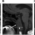
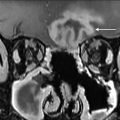
MR imaging findings include loss of T1 signal because fatty marrow is replaced by exudate in acute cases and marked hyperintensity on STIR because of edema or hyperemia. The surrounding soft tissue inflammation has high signal on STIR and T1 contrast-enhanced and fat-saturated images ( Fig. 6 ).

Dental Implant Surgery
Indications
Dental implants have quickly become a mainstream method of replacing missing teeth. Successful osseointegration of these implants depends on the lack of infection, the vitality of the bone following the osteotomy, the presence of adequate bone to support the implant in all dimensions, and a biomechanically sound configuration of the implant and crown replacing the tooth. Evaluation of adequate bone height and width and the proximity to anatomy should be evaluated before implant placement to avoid violating important anatomic structures and to ensure the success of the dental implant.
Radiographic anatomy to consider
Maxilla
- •
Maxillary sinuses: The maxillary sinuses tend to pneumatize the maxillary posterior alveolar processes, notably after the loss of the posterior teeth. This creates inadequate bone height and volume for the placement of implants. Such sinuses could be grafted using particulate graft, which should not be confused for fibro-osseous pathology ( Fig. 7 ).

Fig. 7
Custom sagittal oblique CBCT view shows the high-density granular appearance of a particular sinus graft in a “sinus lift” maxillary posterior alveolar process ridge augmentation.
( Courtesy of A Schetritt, DDS.)
- •
Anterior superior alveolar canal and incisive canal: These canals are in the anterior region of the maxilla. The incisive (nasopalatine) canal is in the midline posterior to the central incisors and, together with bone loss on the facial aspect of the alveolar process, can minimize the amount of bone available of an anterior tooth implant ( Fig. 8 ). The anterior superior alveolar canal branches off of the infraorbital nerve before its emergence through the infraorbital foramen. It descends along the lateral walls of the nasal cavity then converges toward the midline. This more horizontal terminal portion may be injured by canine or lateral incisor implants ( Fig. 9 ).

Fig. 8
Axial CBCT shows a maxillary central incisor implant that is in contact with the incisive canal.

Fig. 9
CBCT panoramic reformation shows an anterior dental implant in contact with the anterior superior alveolar canal.
Mandible
- •
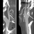
Inferior alveolar canal (IAC): Implants should avoid contacting the canal because its violation may result in paresthesia. This canal can bifurcate and have multiple branches, which should be detected before implant placement ( Fig. 10 ).

Fig. 10
Coronal ( A , B ) and sagittal ( C ) CBCT shows varying degrees of inferior alveolar nerve canal violation.
- •
Mental foramen: The IAC canal travels slightly anterior to the mental foramen in the mandible before making a U-turn to partially emerge from this foramen. This U-turn is called the “anterior loop of the IAC” and should be located to avoid injury.
- •
Incisive canal: After partially emerging from the mental foramen, the IAC continues anteriorly to the midline in the incisive canal and should be identified in the case of anterior implant placement ( Fig. 11 ).

Fig. 11
CBCT panoramic reformation shows a dental implant in contact with the mandibular incisive canal (anterior branch of the IAN canal).
- •
Lingual canal and foramen: This is a midline structure that runs from the lingual surface of the anterior mandible to the center of the basal bone in this sagittal plane. The lingual artery enters through this foramen. Injury by an implant should be avoided.
- •
Submandibular fossa: With disuse atrophy of the mandibular posterior alveolar process, the alveolar process becomes more lingually (medially) positioned while the basal bone remains in its original position. This results in a deepening of the submandibular gland fossa on the medial aspect of the mandible, making the vertical height of the alveolar process available for implant placement shorter. This should be considered because violations of the submandibular gland and fossa may occur ( Fig. 12 ).

Fig. 12
( A , B ) Coronal CBCT shows varying degrees of submandibular fossa violation.
Alveolar processes
- •
Disuse atrophy of the alveolar processes: The primary purpose of the alveolar bone is to support teeth. With the loss of teeth, the bone recedes, making the placement of an adequately long and ideally positioned implant difficult. The dentist should plan on augmenting alveolar processes that have receded to enable adequate position, form, and function of the implant and final crown to prevent failure.
Imaging of success
The CT radiographic imaging of dental implants postplacement is often challenging because of the presence of metal artifact surrounding the implants ( Fig. 13 ), and often two-dimensional intraoral imaging is more useful in detecting bony defects. The alveolar bone should surround the implant with about 1- to 2-mm thickness of bone all around and no visible peri-implant bone loss. The implant should not violate any of the adjacent anatomy, including the teeth and adjacent implants if present. Imaging should be supplemented by clinical examination and probing to detect peri-implant loss of attachment. When planning the implants’ angulation and insertion, special consideration is made for the final function and esthetics of the final tooth prosthesis (crown).

Imaging of complications
An implant that fails to osseointegrate loses radiographic bone attachment (peri-implant bone loss) ( Fig. 14 ). , An implant that violates anatomy should also be evaluated clinically to correlate the symptoms to this violation of anatomy. Graft material that is used to augment the bone for placement of the implant but that does not resorb into the underlying bone shows radiographic signs of detachment and possible fragmentation ( Fig. 15 ).


Imaging of surgical management of benign lesions
Enucleation and Marsupialization
Indications
When a benign lesion of the jaws (odontogenic or nonodontogenic) is present, it often requires surgical removal. The surgical management of the lesion depends on the size, extent, and location of the lesion, which dictates the surgical technique used. Smaller, less aggressive lesions require a more conservative approach, such as enucleation and excisional biopsy, whereas large cysts that inhabit a large portion of the jaws may require a marsupialization approach, which involves creation of a small opening and placing a drain in the cyst wall to relieve the hydraulic pressure of the growing cyst and evacuation of the fluid, allowing for the deposition of bone on the inner surfaces of the cyst cavity, reducing the size of the defect before the removal of the cyst lining to prevent a pathologic fracture from occurring ( Fig. 16 ). , Following enucleation, bone regeneration is more rapid than after marsupialization. However, marsupialization minimizes the danger of damage to adjacent structure and pathologic fracture.

Other large benign lesions may require marginal or complete mandibulectomy or maxillectomy. The more aggressive the lesion and the higher the risk for recurrence, the more aggressive the approach and the wider the excision margin should be.
Imaging of success
The remineralization of the inner portion of the cavity left behind by an enucleated or excised cyst should start to appear radiographically at around 6 to 8 weeks and the cavity should fill in with bone at 6 to 9 months if it is not grafted ( Fig. 17 ), depending on the size of the lesion removed (longer if larger). The lumen of the cavity shrinks concentrically from the outside in mandibular lesions. In maxillary lesions that extend into the maxillary sinus, the shrinking cystic walls in a marsupialized or self-draining cyst leave behind an irregular high-density structure called an involuted or collapsed cyst ( Fig. 18 ). Sometimes, the defect exhibits fibrous healing, which shows soft tissue between the well-defined corticated but irregular margins of the often sclerotic bone ( Fig. 19 ).


Related posts:
 Imaging of Complications of Chemoradiation
 Imaging After Sinonasal Surgery
 Surgical Free Flaps and Grafts in Head and Neck Reconstruction
 Imaging of the Postoperative Eye and Orbit
 Imaging of the Postoperative Skull Base and Cerebellopontine Angle
 Imaging of Facial Reconstruction and Face Transplantation
Stay updated, free articles. Join our Telegram channel

Full access? Get Clinical Tree


