Chapter Outline
Ultrasound-guided percutaneous procedures have several advantages, including real-time assessment and guidance, in which continuous visualization of a needle is possible throughout the procedure. With ultrasound guidance, a needle can be precisely placed in a target while avoiding important structures, such as nerves and blood vessels. This allows very high accuracy and low complication rate, especially compared with blind needle placement. In general, when compared with non-imaging guidance, ultrasound-guided percutaneous needle injections are more accurate, more efficacious, and more cost-effective. Compared with other imaging-guided techniques like computed tomography (CT), ultrasound is especially effective when a target is superficial. In addition, procedure time is typically reduced compared with CT, and ultrasound is not limited to standard imaging planes. Other intrinsic advantages of ultrasound are not specifically related to intervention but include availability, portability, lack of ionizing radiation, and relative low cost.
This chapter first reviews technical considerations when performing an ultrasound-guided procedure. This is followed by topics related to joint, bursal, tendon sheath, tendon, and miscellaneous procedures. Because the procedure that is completed using ultrasound guidance can vary widely (diagnostic or therapeutic injection versus aspiration), the ultrasound guidance aspect is emphasized here, rather than the efficacy of the specific procedure. Regardless of the procedure, if one can identify the target and the needle with ultrasound and understand what structures lie in the projected needle path, ultrasound can offer an accurate and safe method for needle guidance for essentially any procedure. Knowledge of anatomy and of normal and abnormal sonographic findings is essential to accurately identify a target. Of note, the photographs in this chapter that show needle and transducer placement are for illustrative purposes only, in that sterile technique and needles were not used. Examples of interventional ultrasound reports are shown in Boxes 9.1 and 9.2 .
Examination: Ultrasound-Guided Injection of Right Biceps Brachii Long Head Tendon Sheath
Date of Study: March 11, 2017
Patient Name: James Murphy
Registration Number: 8675309
History: Pain
Findings: Limited ultrasound over the anterior right shoulder demonstrates minimal joint fluid distending the biceps brachii long head tendon sheath. No evidence for hyperemia or synovial hypertrophy to suggest tenosynovitis. No evidence for biceps brachii long head tendon tear. No tendon subluxation or dislocation with dynamic imaging. No abnormal subacromial-subdeltoid bursal thickening.
After obtaining both written and verbal informed consent discussing potential risks (bleeding, infection, soft tissue injury) and benefits, using sterile technique and local anesthetic injection (provide type and amount), a 22-gauge spinal needle with trocar was inserted into the long head of the biceps brachii tendon sheath. Intra-sheath location of needle tip was confirmed with a small amount of anesthetic injection. This was followed by corticosteroid injection (provide type and amount).
The patient tolerated the procedure well without complications. The patient’s pain level changed from 8/10 before procedure to 2/10.
Impression:
- 1.
Limited diagnostic ultrasound of the anterior shoulder showed minimal joint fluid.
- 2.
Successful long head biceps brachii tendon sheath corticosteroid injection with pain relief as noted above and without complications.
Examination: Ultrasound-Guided Right Iliopsoas Bursal Injection
Date of Study: March 11, 2011
Patient Name: Chazz Reinhold
Registration Number: 8675309
History: Pain, evaluate for tendon tear
Findings: Limited ultrasound over the anterior right hip showed no hip joint effusion and unremarkable anterior hip labrum. The rectus femoris was normal. No evidence for iliopsoas bursal distention. Dynamic imaging showed no evidence for snapping iliopsoas tendon.
After obtaining both written and verbal informed consent discussing potential risks (bleeding, infection, soft tissue injury) and benefits, using sterile technique and local anesthetic injection (provide type and amount), a 20-gauge spinal needle with trocar was directed between the psoas major tendon of the iliopsoas complex and ilium superior to the femoral head. Needle tip location between the tendon and ilium was confirmed with a small amount of anesthetic injection. This was followed by corticosteroid injection (provide type and amount).
The patient tolerated the procedure well without complications. The patient’s pain level changed from 8/10 before procedure to 2/10.
Impression:
- 1.
Limited diagnostic ultrasound of the anterior right hip showed no abnormality.
- 2.
Successful right iliopsoas bursal corticosteroid injection with pain relief as noted above and without complications.
Technical Considerations
Needle Guidance Overview
When performing a percutaneous needle procedure using ultrasound guidance, there are several techniques that can be used. Generally speaking, ultrasound-guided procedures can be separated into indirect and direct approaches. With the indirect approach, ultrasound is used to identify a target and to determine the depth, and then the skin directly overlying the target is marked. The transducer is removed, and the needle is directed perpendicular to the skin into the target. This approach may work for large superficial targets but is significantly limited because the needle is never directly visualized in the target, and real-time assessment during the procedure is not possible. Therefore, the direct approach, where the needle is visualized with ultrasound within the target, is preferred over the indirect approach to ensure a much higher accuracy and lower complication rate.
There are several techniques that may be employed when using the direct approach, which includes either needle guide or freehand techniques. The use of a needle guide, in which a guide is physically attached to the ultrasound transducer, is not routinely used for musculoskeletal procedures. Because most musculoskeletal procedures are relatively superficial, and given the extra steps required when using a needle guide, a freehand approach is favored.
When using the freehand direct approach, there are two methods to direct a needle relative to the transducer and sound beam: in plane and out of plane. With the in-plane approach, the needle is directed under the long axis of the transducer and sound beam in plane, and the entire needle, including its tip, is visible at all times during the procedure ( Fig. 9.1 ) ( ). This enables real-time correction of angle and depth while the needle is advanced. The in-plane approach is the preferred method in most situations because continual visualization of the entire needle, including the needle tip and target, minimizes complications and maximizes accuracy when compared with the out-of-plane approach.

With the out-of-plane approach, the needle is passed perpendicular to the transducer so that the needle passes through the plane of the sound beam ( Fig. 9.2 ) ( ). The disadvantage with this approach is that only a short segment of the needle is seen where the needle passes through the sound beam plane. When using the out-of-plane approach, the needle entrance site is centered over the target, and the needle enters from the side of the transducer (see Fig. 9.13 ). When inserting the needle, there is some trial and error required as the needle passes through the sound beam, is retracted, and then repeatedly redirected, typically deeper, to eventually get to the target. Another disadvantage is that one cannot determine what segment of the needle is represented on the ultrasound image, the shaft or tip of the needle, because they look exactly the same as a single bright echo with reverberation artifact. Although the in-plane approach is preferred in most situations, the out-of-plane approach may be used in situations in which the target is very superficial, such as guiding a needle into small joints of the hand and foot. Regardless of the in-plane or out-of-plane approach, once the needle is seen in the target, it is critical that the transducer is turned 90 degrees to confirm accurate location of the needle tip.

Approach, Transducer and Needle Selection, and Ergonomics
The first step in planning an ultrasound-guided procedure (after performing a diagnostic ultrasound to identify the target and pertinent surrounding anatomy) is proper positioning of the patient. I prefer to always have the patient supine when performing any procedure, to avoid the potential for a vasovagal reaction (the patient). Next, the generalized needle approach and transducer plane are planned before marking and cleansing the skin. When performing an extremity procedure, there is often a choice between having the needle enter along the flat surface of the extremity or the curved surface. There are several benefits of having the needle enter along the curved surface, including more room to work in the space next to the extremity rather than directly over the flat surface of an extremity. Another advantage is that the puncture site can be an increased distance from the transducer ( Fig. 9.3 ). This is helpful in that the needle can be more perpendicular to the sound beam (and therefore more conspicuous), and in addition the needle is not directly touching the transducer, which comes into play depending on the level of aseptic technique (see discussion later in the chapter).

Transducer choice should also be considered at this time. In procedures of the extremities involving the elbow, wrist, hand, knee, ankle, and foot, a linear transducer greater than 10 MHz is typically used because the target is usually superficial. A high-frequency transducer provides the highest resolution, and the sound beam projecting in a linear fashion parallel to the transducer face creates an echogenic appearance of the needle (see Fig. 1.1A ). A small-footprint transducer is often helpful at the distal extremities; often, a larger footprint transducer does not make contact with the full surface of the skin because of the multiple curvatures of the distal extremities and decreased thickness of soft tissues compared with more proximal joints. An offset to a small-footprint probe (often referred to as a hockey-stick design ) is not required but is helpful when performing procedures of small parts because the hand holding the transducer is then away from the puncture site, improving visualization at the puncture site (see Fig. 1.1C ). When performing procedures of the shoulder and hip, a curvilinear transducer is often selected (see Fig. 1.1B ). The benefits of this type of transducer include a larger field of view of deeper structures and a lower frequency, improving sound beam penetration. In addition, the sound beam is emitted in a more radial fashion, which helps to improve conspicuity of a needle that is steeply angled to reach a deep target.
With regard to needle selection, in general I prefer a 20-gauge spinal needle (3.5 inches long) for shoulder and knee procedures, and a 22-gauge needle (either 3.5 or 1.5 inches long) for more distal procedures, and a 25-gauge needle for superficial injections. Regardless of needle gauge, a stiffer needle is preferred to avoid bending of the needle. Because the goal of the direct in-plane method is to have the needle aligned with the ultrasound beam, a bent needle would not be fully visible in the ultrasound beam. A needle with a trocar (or stylet) may improve conspicuity at ultrasound and will ensure that the needle easily passes through fascial planes and does not get plugged with tissue as the needle is advanced. There are several disadvantages of using a needle with a trocar. One is that the transducer must be set down so that one’s hand is free to remove the trocar and attach a syringe for injection or aspiration. Another disadvantage is that the needle contains air once this trocar is removed. This becomes problematic during an injection in that the air within the needle is initially injected into the soft tissues, which obscures the target. This latter problem can be avoided if the needle advancement stops short of the target, the trocar is removed, and a small amount of saline or anesthetic agent is injected to displace the air from the needle, and then the needle can be advanced to the target so that the definitive injection will contain air. I prefer to only use a trocar when aspirating to simplify the procedure and avoid the extra steps just described.
With regard to ergonomics, it is essential that the operator is comfortable during a procedure. I prefer to have the ultrasound monitor directly beyond or within 45 degrees to either side of the patient to enable full view of the ultrasound image without excessive turning of the head or spine. A wall-mounted accessory monitor with an adjustable arm is very effective. I also prefer to have a stool on wheels to minimize fatigue and maximize mobility. Typically, the operator’s dominant hand should hold the needle, and the other hand should hold the transducer, although it is ideal to develop ambidextrous skills. For the in-plane approach the transducer can be positioned on the patient so that the needle is entering from the right or left side, or the transducer and needle may be aligned as though one is looking down a gun site.
Prepping the Site
The first step in the procedure after finding the target, determining the approach, and choosing the transducer is marking the skin. This is completed before cleansing the skin and before sterile conditions. With a direct method of needle guidance, the transducer is placed over the target and the puncture site is determined. A mark is placed at the puncture site (such as an X ), and a line is placed at the other end of the transducer to indicate the imaging plane ( Fig. 9.4 ). The use of a surgical marker will help to ensure that the marks are not washed off during cleansing of the skin. If using the indirect method, an opened paper clip passed between the transducer face and the skin can be used to accurately mark the skin directly over a target ( ).


With regard to sterile technique, the use of a probe cover and preparing a sterile field at the puncture site will minimize the risk of infection. A comprehensive sterile field is essential in that ultrasound gel can act as a conduit for infection from non-cleansed areas, even if the ultrasound gel is itself sterile. Although sterile preparation of the site can take variable forms, the following represents the procedure used by this author. First, the sterile procedure tray is opened, and appropriate needles, syringes, and sterile ultrasound probe cover are gently dropped onto the sterile tray. The transducer to be used is placed in the transducer holder of the ultrasound machine (if present), and a thick layer of non-sterile ultrasound gel is placed on the transducer face ( Fig. 9.5A ). After washing hands, the operator wears sterile gloves and prepares the procedure site with chlorhexidine solution. Sterile drapes or towels are placed around the puncture site covering the areas not washed with chlorhexidine solution. The puncture site is anesthetized with local anesthetic using a 25-gauge needle. The sterile probe cover is then held covering the operator’s sterile hand, and the probe cover is placed over the non-sterile probe and gel ( Fig. 9.5B and C ). The operator then extends the probe cover along the transducer cable ( Fig. 9.5D and E ) and secures the cover with sterile rubber bands (included with the probe cover). Alternatively, an assistant can fill the inside of the sterile probe cover with non-sterile gel and lower the probe into the sterile probe cover ( Fig. 9.5F ). Sterile gel that is also included in the sterile probe cover kit is then opened and deposited on one of the sterile drapes near the puncture site. The transducer in the cover is then dipped into the sterile gel and placed between the X and the line to reconfirm the target. The probe is removed from the site, and the procedure needle enters the skin (about 1 cm) at the puncture site. The transducer is returned to the procedure site to visualize the needle. Of note, the transducer is removed from the procedure site until the needle penetrates the skin to avoid inadvertent puncture of the transducer or transducer cover. With a sterile field placed around the procedure site, the operator can easily set the transducer down on the field while exchanging syringes, minimizing contamination.


Needle Visualization
The first critical rule when performing the in-plane method of needle guidance is that the needle should not be advanced unless it is seen in its entirety (when using in plane technique); otherwise, the procedure is essentially blind and not image guided. As stated earlier, the procedure is initiated when the needle is placed through the skin at the puncture site about 1 cm. At this point, the transducer is placed over the projected needle path, and the echogenic needle is identified. This is accomplished by moving the transducer side to side over the needle. Because the sound beam is focused, it is not uncommon to have the needle directly under the transducer but not visible on the ultrasound image. Side-to-side movement of the transducer should only be 1 mm at a time so as not to move the transducer away from the needle. Moving the probe too fast or abruptly is a common reason why the needle is not visualized. It is often helpful to look down at the procedure site to ensure that the needle is indeed beneath and parallel to the transducer plane. Once again, the needle should not be advanced until seen in its entirety.
Once the needle is visualized in long axis, the target should also be visualized. If the needle is seen but the target is not visible, the transducer can then be rotated to line up the puncture site with the target. By looking down at the new probe direction, the needle can be easily angled into the same transducer plane so that both the needle and target can be seen. This can only be accomplished with the needle in the subcutaneous fat, where needle movement is effortless and without symptoms. This is one reason why the needle and target should both be visualized in the same plane prior to advancing the needle given the flexibility in optimizing transducer, needle, and target alignment. Once the needle enters the deeper muscle tissues and fascial planes, movement of the needle or correction of needle path is limited and often painful.
Another basic concept is that the needle and transducer should not be moved at the same time. The transducer is moved to identify the needle, and the needle is then advanced (see ). If the needle is no longer visualized during the procedure, needle advancement is stopped, and the transducer is moved as it was before, until the needle is again visualized and fully in plane. The transducer is then fixed in position as the needle is advanced again.
If a target is very superficial, the procedure may be more difficult; when the needle penetrates the skin the needle tip may already be either in the target or have missed the target. To assist, a sterile gel standoff may be considered ( Fig. 9.6 ). With this technique, one end of the probe is lifted off the skin and sterile gel is placed. The needle can then be visualized within the gel prior to penetrating the skin and then redirected as needed for accurate needle placement within the target.


There are several options to improve conspicuity of the needle with ultrasound. A larger needle with a trocar may help, but a larger needle is not chosen for this reason. Coated or etched needles may be used, making the needle more echogenic ( Fig. 9.7 ). This is helpful when performing a procedure where the target is deep and the needle angle is steep, which decreases needle conspicuity due to needle anisotropy. A very helpful option is to “jiggle” the needle while slowly moving the transducer over the projected needle path ( ). With this maneuver, the needle is moved minimally forward and backward along the needle path, similar to needle movement with an intention or caffeinated tremor, which causes movement of the adjacent soft tissue and can help locate the needle. Of note, the needle in this maneuver is not advanced or moved side to side. To identify this distal tip of the needle, the needle can be rotated, which will create an echogenic focus as the bevel becomes more perpendicular to the sound beam ( ). The most important technique to improve visualization of the needle is to have the needle as close to perpendicular to the sound beam as possible. Similar to anisotropy of tendons, a needle that is oblique to the sound beam will be less echogenic ( Fig. 9.8A ), whereas a needle that is perpendicular will be very echogenic with a strong reverberation artifact (see Fig. 9.1B ) ( ). A perpendicular alignment between the sound beam and needle can be accomplished by having the puncture site farther removed from the transducer, which is possible when performing a procedure along the curvature of an extremity (see Fig. 9.3B ). Another option is to move the transducer or deform the soft tissues with a heel-toe maneuver (see Fig. 9.3C ). Many ultrasound machines have the ability to steer the ultrasound beam so that the insonation angle between the needle and the beam is ideally perpendicular to eliminate needle anisotropy ( Fig. 9.8B ).


When attempting to align the needle along the long axis of the sound beam, as in the in-plane approach, only a short segment of the needle may be visualized. This finding indicates that the transducer alignment and needle are not parallel but instead are crossing each other ( Fig. 9.9 ). The longer the visible segment, the more the needle and sound beam are parallel. To correct this, the transducer should be turned clockwise or counterclockwise. If the segment of needle is increasing in length, the rotation is in the correct direction because the needle and sound beam become more parallel ( ). On the contrary, if the segment of needle becomes shorter, the transducer is being turned in the wrong direction because less of the needle is in the sound beam path. It is easiest to simply look down at the needle and transducer plane to determine which direction to rotate the probe to achieve parallel planes.

Joint Procedures
Percutaneous joint procedures can include aspiration (for infection or crystal analysis), injection (both diagnostic and therapeutic using anesthetic agents or corticosteroids, or for the purpose of injecting contrast before MRI or CT), or less commonly synovial biopsy. Accuracy of such procedures is improved compared with blind attempt if the needle tip is directly visualized with ultrasound within the target. One key concept is that nearly every synovial joint in the extremity has one recess that preferentially distends with joint fluid and is visible at imaging. These recesses directly communicate with their respective joint articulations so that a joint procedure targets these sites rather than the joint articulations, which would potentially harm fibrocartilage and hyaline cartilage. These distinct joint recesses are assessed for joint fluid or synovial hypertrophy and are targeted for the joint procedure.
When accessing a joint recess for a procedure, the specific recess of a joint is assessed. If there is distention of the recess with fluid, that site would be the ideal target. If the recess is not distended, then the site is still targeted, although injection of a collapsed recess is more difficult. In this situation, intra-articular needle placement should be confirmed prior to the diagnostic or therapeutic injection. This is accomplished with a test injection of local anesthetic or saline. Uncommonly, if a joint recess is not distended, a needle can be directly advanced into a joint articulation, such as accessing the sacroiliac joint or first carpometacarpal joint. Joint injection can be completed with almost any needle gauge, although I prefer a 20- or 22-gauge needle for stiffness. Joint aspiration should be at least 20 or 22 gauge, with 18 gauge considered if joint fluid is heterogeneous. Synovial biopsies may be completed with soft tissue core biopsy guns, whereas 22-gauge needles with short throw (i.e., 1 cm) are preferred given the small sizes of the various joint recesses ( ). Biopsies of synovial hypertrophy tend to be reserved to evaluate for atypical infection or synovial proliferative disorders (such as pigmented villonodular synovitis); such biopsies in the setting of a systemic inflammatory arthritis often reveal nonspecific inflammation.
Shoulder
Regarding the shoulder joint, joint effusions accumulate within the biceps brachii tendon sheath because this space openly communicates with the glenohumeral joint (in the absence of biceps brachii long head tenosynovitis). Other glenohumeral joint recesses include the axillary recess, the subscapularis recess, and the posterior glenohumeral joint recess (assessed in external rotation). To access the glenohumeral joint, a posterior approach targeting the posterior glenohumeral recess is preferred ( Fig. 9.10 ). The transducer is placed long axis to the infraspinatus, and the needle is advanced in plane from lateral to medial (or medial to lateral) until the needle tip is located at the surface of the humeral head hyaline cartilage (see ). The joint recess is wider more medial adjacent to the hyperechoic fibrocartilage labrum, especially with external rotation of the shoulder. The biceps brachii tendon sheath is not typically targeted for glenohumeral joint access because open communication between the biceps sheath and joint may not always be present in the setting of biceps tenosynovitis.

The acromioclavicular joint can be accessed in several different ways. I prefer an in-plane needle approach with the transducer in the coronal plane on the body and the needle passing superficial to the acromion and entering from lateral to medial ( Fig. 9.11 ) ( ). Another method is an in-plane approach with the transducer in the sagittal plane and the needle entering from anterior to posterior ( Fig. 9.12 ), although this technique may be difficult if the joint space is narrowed. Lastly, an out-of-plane approach may be used with the transducer in the coronal plane on the body ( Fig. 9.13 ). With regard to the sternoclavicular joint, I prefer an in-plane approach from lateral to medial to avoid structure deep to the joint ( Fig. 9.14 ) although an out-of-plane approach can also be used.


Elbow
For the elbow joint, the most sensitive location to identify a joint effusion by ultrasound is the posterior olecranon recess (in the olecranon fossa) with the elbow flexed, where a joint effusion or synovial process displaces the adjacent hyperechoic fat pad posterior and superior. Needle placement is transverse to the extremity, in plane with the transducer, with the needle advanced from lateral to medial ( Fig. 9.15 ) ( ). Positioning of the elbow in slight extension prior to needle placement may redistribute the joint fluid more superficially, aiding in aspiration.

Wrist and Hand
With regard to the wrist and hand, the dorsal recesses are the typical accessible targets. There are three wrist joints: distal radioulnar, radiocarpal, and midcarpal. For all three of these joint recesses, I prefer the in-plane approach with the transducer in the axial plane on the body and the needle entering from ulnar or radial along the curvature of the extremity ( Fig. 9.16 ) ( ). The radiocarpal joint may also be accessed in the sagittal plane as well. Aspiration of the small joints of the hand can be more difficult given their superficial location. The dorsal recesses are targeted either with an in-plane approach in the parasagittal ( Fig. 9.17A ) or transverse plane ( Fig. 9.17B ), or an out-of-plane approach ( Fig. 9.17C ). With either approach, the overlying extensor tendon in the sagittal plane and the neurovascular structures at the medial and lateral aspects must be avoided.


Hip and Pelvis
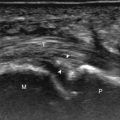
For needle placement into the hip joint, the anterior joint recess overlying the femoral neck is the preferred target. Placing the needle over the femoral head is not recommended as this increases likelihood of the injection being extra-articular, and needle placement more superiorly can potentially harm the acetabular labrum. The needle is guided into the anterior hip joint recess with an in-plane approach long axis to the femoral neck in the sagittal-oblique plane ( Fig. 9.18 ) ( ), although an in-plane lateral to medial approach can also be used. Because of the depth of the target in many adults, the needle is often quite oblique to the sound beam, which makes the needle less echogenic from anisotropy. The use of a curvilinear transducer is often helpful in this situation. As described earlier, for injecting a collapsed joint recess it is often helpful to first inject local anesthetic to ensure accurate intra-articular needle placement before final injection.