Fig. 4.1
Stable and unstable human coronary artery atherosclerotic plaque histopathology. Example cross-sectional photomicrographs from human coronary artery autopsy specimens with mild to severe luminal stenosis demonstrating plaque rupture, prototypical high-risk “vulnerable” plaques known as thin-cap fibroatheroma (TCFA), and stable plaques. Ruptured plaques exhibit intraluminal thrombus (Thr) that may be (a) nonocclusive, (b) partially occlusive, or (c) completely occlusive. (d–f) TCFA are notable for the presence of a large necrotic core (NC) separated from the lumen by a thin-walled fibrous cap, without intraluminal thrombus formation as observed in ruptured plaques. (g–i) Stable plaques, also known as fibroatheroma, reveal relatively smaller necrotic core with regional calcification (Ca ++ ) (Reprinted with permission from Narula et al. [15])
Biologically, autopsy studies following sudden cardiac death have identified enhanced inflammation, neovascularization, and apoptosis as histological markers associated with plaque disruption [4,16]. Inflammation is of particular interest given its potential as a treatment target in high-risk individuals. Macrophages function as the primary effector cells in inflamed atherosclerotic plaques, where they orchestrate the release of cytokines and proteases that cause plaque growth and destabilization and undergo apoptosis and necrosis to expand the necrotic core [17].
4.2.1 Plaque Proteolytic Activity
Proteases liberated from plaque macrophages have been heavily evaluated with respect to plaque vulnerability [18,19]. Precursor proteases mobilized to the macrophage surface become activated and mediate degradation of the collagen and elastin extracellular matrix network, thus structurally weakening the plaque in general and compromising the integrity of the overlying protective fibrotic cap [20]. This sequence of events has been implicated in the development and evolution of high-risk TCFA from more stable plaque phenotypes [21] and with mechanical instability of the rupture-prone fibrous cap shoulder regions that experience high wall stresses [22,23].
In vascular disease, activated serine and cysteine proteases, as well as matrix metalloproteinases (MMP), have been shown to be critical elements in plaque destabilization [19,24]. Histologic studies of inflamed plaques demonstrate overexpression of cathepsins, a family of cysteine proteases [25,26], and MMPs [18,27,28]. Given their association with plaque rupture and remodeling, proteases have proven to be a rich source of high-value plaque imaging targets [29–34], and hold particular promise as agents for intravascular coronary artery imaging applications [35].
4.3 Coronary Artery Molecular Imaging
Compared to larger-sized arteries, imaging the coronary arteries poses special challenges. First, most epicardial coronary arteries of interest are 2–4 mm luminal diameter necessitating imaging platforms with high spatial resolution to resolve local phenomena. To enable interrogation of individual plaques, resolution demands increase significantly, on the order of tens of micrometers. Second, cardiac and respiratory motion requires high temporal resolution systems and often gating to the electrocardiogram, in order to sample rapidly enough to avoid blurring. In comparison, large arteries such as the carotids are relatively fixed in space, making motion artifacts less problematic. Overall, meeting the stringent requirements for successful coronary artery imaging remains a major challenge.
4.3.1 Clinical Trials
Current efforts to apply molecular imaging strategies to human coronary arteries have employed noninvasive techniques with PET imaging of FDG and 18F-sodium fluoride (NaF) to measure coronary plaque metabolism/inflammation and osteogenesis, respectively. FDG PET has preliminarily identified a subset of inflamed coronary plaques in pilot studies of patients with acute coronary syndromes, stable angina, and following coronary stenting (Fig. 4.2) [12,36–38]. NaF PET, historically used in bone scans, has more recently been employed in small studies to detect coronary artery osteogenesis in different patient populations and has the advantage of having minimal myocardial background uptake compared to FDG [11]. Ultrasmall superparamagnetic iron oxide (USPIO) nanoparticles, another clinically tested macrophage-targeted agent detectable by MRI, have shown utility for large-artery inflammation imaging [39–41], but the relatively lower temporospatial resolution of MRI to image-small plaques in the highly dynamic coronary environment has limited its utility.
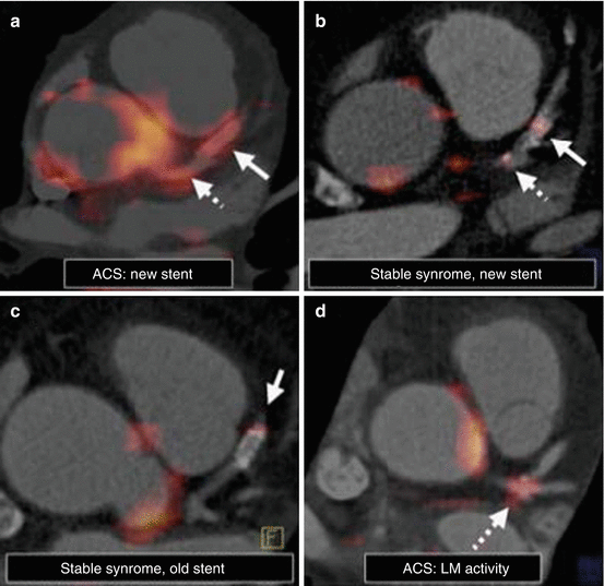

Fig. 4.2
Noninvasive coronary artery hybrid FDG-PET/CT imaging of inflammation in patients presenting with stable angina or acute coronary syndrome (ACS). (a, d) ACS subjects demonstrate increased FDG uptake in the left main (LM) coronary artery (hatched arrows) and at a newly placed stent (solid arrows). (b, c) While FDG activity is present in stable syndrome patients, it is of lower intensity than ACS. Furthermore, a more recently placed “healing” stent exhibits relatively greater FDG signal than an older “healed” stent that was implanted months earlier. CT computed tomography, FDG fluorodeoxyglucose, PET positron emission tomography (Reproduced with permission from Rogers et al. [12])
Coronary plaque imaging with FDG-PET and NaF-PET has important limitations, however, as they both possess lower spatial resolution and require ionizing radiation. Furthermore, due to intense FDG uptake in the highly metabolically active myocardium that obscures coronary wall FDG signal, only the left main and most proximal coronary artery segments can be reliably evaluated by FDG [12]. Attempts to suppress myocardial FDG uptake with high-fat dietary protocols have met moderate success [38], but still a significant number of segments remain uninterpretable.
Given the challenges of noninvasive clinical coronary molecular imaging, new approaches to evaluate coronary inflammation in vivo are being investigated. A particularly promising translational imaging technique that can detect inflammation and protease activity in coronary-sized arteries involves intravascular optical imaging using near-infrared fluorescence (NIRF) [42,43].
4.4 Intravascular NIRF Imaging
Offering high resolution and good sensitivity to fluorescence imaging agents, NIRF molecular imaging has advantageous technical specifications to enable atherosclerotic plaque imaging in coronary arteries. NIRF employs light wavelengths in the near-infrared window (700–900 nm) with relatively low blood absorbance and reduced tissue autofluorescence at a reasonable depth penetration [44,45]. These properties are highly favorable for intravascular NIRF imaging of the 2–4 mm diameter epicardial coronary arteries, which can be obtained through blood without the need to displace blood from the imaging field by vessel occlusion and flushing [46]. Furthermore, light-based NIRF imaging is safe and does not expose the patient to the hazards of ionizing radiation associated with CT and nuclear imaging (e.g., PET, SPECT). On the other hand, catheter placement for intravascular imaging carries risk to the subject (e.g., vessel spasm, perforation, dissection), and, therefore, decision tools for appropriate selection of patients that may benefit from intravascular NIRF imaging will be important for clinical translation of this technology.
NIRF has been utilized extensively in preclinical and clinical imaging studies in cardiovascular disease and oncology, illuminating important in vivo pathobiology not previously available for interrogation by structural imaging modalities. A broad and versatile range of NIRF molecular imaging agents have now been established, utilizing the latest advances in nanotechnology and bioengineering [10,47]. Specifically for atherothrombosis applications, in vivo NIRF agents have successfully exposed enhanced endothelial adhesion molecule expression, upregulated macrophage inflammation, thrombin activity, and plaque proteolysis.
4.4.1 Intravascular NIRF Imaging Platforms
Recent technological advances have witnessed a growing presence of optical intravascular imaging systems available for clinical use [5,35,48,49]. Currently, physicians have access to two FDA-approved catheters for light-based atherosclerosis imaging, optical coherence tomography (OCT), and near-infrared spectroscopy (NIRS). OCT, and its second-generation high-speed counterpart termed optical frequency domain imaging (OFDI), generates excellent axial resolution (~10 μm) structural images of the vessel wall by analyzing reflected near-infrared light [50]. OCT/OFDI can visualize all three layers of the artery wall, thrombus, stent struts, and plaques with lipid pools, calcification, and thin fibrous caps. OCT is limited by relatively arterial wall penetration depth (1–2 mm), and the need for a blood-free imaging field. NIRS is a newer spectroscopic approach that can identify lipid within the vessel wall based on near-infrared cholesterol absorbance patterns [51–53]. Since intravascular NIRF is also a light-based imaging approach utilizing flexible optical fibers that can be housed in a catheter design similar to the currently FDA-approved devices, the development of NIRF imaging catheter systems applicable for human coronary artery imaging is feasible. Recently, promising translational intravascular NIRF molecular imaging platforms have been developed and tested in vivo in large animal models of atherosclerosis and stent healing.
4.4.1.1 One-Dimensional In Vivo Intravascular NIRF Sensing
A first-generation intravascular NIRF imaging prototype was developed in 2008 to test the feasibility of detecting NIRF activity in living subjects [54]. This early system was constructed from a near-infrared optical sensing fiber that was manually pulled back through the vessel to identify local NIRF signal (Fig. 4.3). Performance characteristics demonstrated NIRF detection in a 40 μm diameter focal spot approximately 2 mm from the catheter imaging source. However, without automated translation and rotation capabilities, this one-dimensional NIRF system lacked comprehensive 360° vessel NIRF detection and therefore could only collect data from a localized sector of the vessel wall. In addition, this stand-alone NIRF imaging system did not provide anatomic information and therefore required the use of a sequential structural intravascular imaging platform (e.g., IVUS, OCT/OFDI) to attempt localizing NIRF signal to endovascular regions of interest.


Fig. 4.3
One-dimensional intravascular NIRF catheter prototype. (a) Atherosclerotic-prone rabbits developed iliac artery plaques (arrowheads) following balloon injury. (b) A 90° NIRF-sensing guidewire without rotational capability (lower inset), fabricated to specifications of 0.48 mm/0.019 inch maximum outer diameter with a 0.036 mm/0.014 inch radiopaque tip, was easily maneuvered across the stenoses within the iliac artery (arrowhead). As a working distance of 2 ± 1 mm, phantom testing revealed a 40 ± 15 μm NIRF spot size (upper inset). (c) Resected tissue grossly confirms the presence of iliac atherosclerosis in the balloon-injured areas (Reproduced with permission from Jaffer et al. [54])
4.4.1.2 Two-Dimensional In Vivo Intravascular NIRF Imaging
To overcome the lack of circumferential NIRF detection and inability for precise longitudinal anatomic localization in the one-dimensional NIRF catheter design, a second-generation NIRF imaging system was engineered [46]. This two-dimensional NIRF catheter was coupled to computer-controlled motors for automatic 360° rotation and 0.5 mm/s translation pullback (Fig. 4.4). In fluorescent phantom experiments submerged in an artificial blood-like media, the two-dimensional NIRF system had an angular resolution of 35–42° (i.e., ability to resolve >8 sectors) and longitudinal resolution of 1.0 mm at catheter-to-phantom distances of 3.0 and 2.0 mm, respectively. Although the two-dimensional intravascular NIRF imaging system marked a major step forward toward achieving detailed, comprehensive plaque characterization, it suffered from the same drawback as the one-dimensional NIRF prototype – being a stand-alone modality without accompanying structural imaging information.
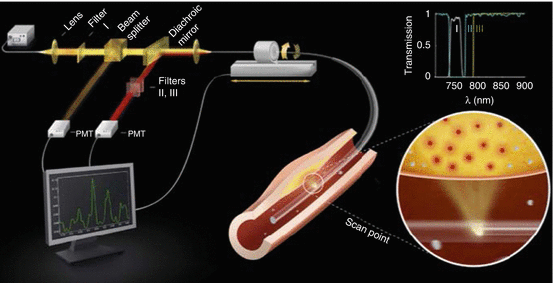

Fig. 4.4
Two-dimensional intravascular NIRF catheter schematic. Near-infrared light is delivered from a laser through specialized optical fibers within the catheter and then redirected 90° by a coated prism at the fiber tip to illuminate the artery wall (bottom right circular inset). Fluorescent light emissions from molecules excited by the near-infrared laser are collected via the prism, transmitted through the fiber, filtered by wavelength-selective mirrors (top right inset show filter spectra), and detected by a photomultiplier tube (PMT) for computer display and analysis. The catheter position is controlled by an automated pullback motor with rotational and translational capabilities (Reproduced with permission from Jaffer et al. [46])
4.4.1.3 In Vivo Intravascular NIRF-OFDI Molecular-Structural Imaging
In a major advance for intravascular NIRF imaging, NIRF was recently paired with OCT/OFDI in a hybrid catheter system to overcome the limitations of earlier one- and two-dimensional stand-alone NIRF catheter systems [55]. As intravascular NIRF imaging lacks anatomical information, the addition of exactly co-registered OFDI allows precise mapping of the local NIRF signal with plaque microstructure. The design of the NIRF-OFDI system employs specialized fiber optics that can simultaneously transmit NIRF through the outer fiber cladding and OFDI through the central core. The distal end of the imaging fiber is coupled to a hand-drawn ball lens that directs light into the tissues at 90° to the optical fiber axis. At the back end, the optical fiber is coupled to the image-processing interface by a customized rotary junction that allows high-speed image acquisition simultaneously from both NIRF and OFDI channels during catheter pullback (Fig. 4.5). In benchmark testing, the NIRF-OFDI system performance was excellent at approximately 7 and 30 μm axial and transverse resolution, respectively, 25.4 frames per second image acquisition, up to 20 mm per second automated pullback speed, a 4.6 mm imaging field depth in saline, and <1 nM sensitivity for near-infrared fluorochromes. Overall, the NIRF-OFDI imaging system offers distinct advantages for enhanced diagnosis over either imaging platform alone and holds great promise for clinical use.
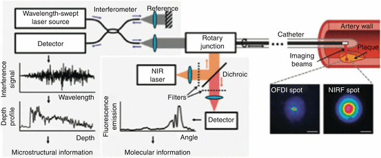

Fig. 4.5
Integrated NIRF-OFDI molecular-structural imaging catheter design. Coupled by a custom-engineered rotary junction to allow automated rotation and translation, NIRF and OFDI imaging systems are combined within a specialized dual-clad optical fiber housed in a clinical-grade intravascular imaging catheter to simultaneously deliver NIRF and OFDI laser light to image the artery wall. The dual-clad fiber contains concentric rings with different optical properties to separate the NIRF and OFDI light paths, and a custom-fabricated ball lens at the fiber tip that focuses incident light to a small spot and redirects it 90° into the tissue (scale bars, 100 μm). Returning light from the tissue collected by the ball lens is transmitted through the optical fiber and selectively filtered for detection by sensitive photomultipliers. OFDI microstructural information (depth profile) is constructed by analyzing the interference pattern between the back-reflected light with a reference arm as the laser wavelength source is rapidly cycled. Quantitative NIRF molecular information (fluorescence emission) is simultaneously acquired at every OFDI depth profile acquisition (Reproduced with permission from Yoo et al. [55])
4.4.1.4 In Vivo Intravascular NIRF-IVUS Imaging
New catheter designs pairing intravascular NIRF with IVUS are also being developed, given the longstanding experience with IVUS in modern-day cardiac catheterization laboratories, where IVUS has been the clinical standard intravascular imaging modality [56,57]. Furthermore, NIRF-IVUS holds technical advantages over NIRF-OFDI in certain areas, despite OFDI exhibiting higher spatial resolution than IVUS. Compared to OCT/OFDI that requires rapid flushing with saline or, more commonly, iodinated contrast to displace blood from the imaging field, both IVUS and NIRF can image the vessel wall through blood without the need for flushing. Eliminating coronary artery flushing by using a NIRF-IVUS system can be time saving, decreases the small incremental risk of vessel trauma and arrhythmias associated with flushing, and lessens the overall contrast load that can result in acute kidney injury. Furthermore, IVUS has improved tissue depth penetration over OCT/OFDI and the ability to image coronary ostia that cannot be evaluated with OCT/OFDI due to difficulty effectively flushing blood from these locations. In evaluation of the left main coronary artery, these characteristics give IVUS a distinct competitive advantage over OCT/OFDI [58].
4.4.2 Intravascular NIRF Imaging Applications to Atherosclerosis
NIRF molecular imaging has the ability to uncover critical in vivo biological aspects of high-risk, “vulnerable” atherosclerotic plaques. The fundamental assumption underlying this approach to plaque imaging is that through in vivo detection of high-risk features previously linked to plaque rupture and progression by detailed histopathology that the morbidity and mortality associated with atherosclerosis complications may be lessened through early pharmacological or mechanical interventions. For example, these interventions may take the form of more aggressive medical management with traditional lipid-lowering agents or employ new anti-inflammatory and plaque-stabilizing therapeutics currently being benchmarked in preclinical and early phase clinical trials. In select cases, there may be opportunities for invasive treatment with catheter-based local drug delivery or even preventative stenting. While the opportunities for atherosclerosis management based on intravascular NIRF molecular imaging reporters are yet to be established and will require large-scale outcomes trials for validation, there is significant expectation that the biological information garnered from intravascular NIRF will inform new treatment targets and the development of goal-directed strategies.
4.4.2.1 NIRF Imaging of Cysteine Protease Activity in Inflamed Plaques
Complications related to atherosclerotic plaques prototypically involve rupture of the overlying protective fibrous cap, exposing thrombogenic elements to the circulating bloodstream [16,59]. Enhanced plaque proteolytic activity, which results in degradation of structurally important collagen and elastin fiber networks, has been mechanistically linked to plaque rupture [19]. In particular, cathepsins, a well-described cysteine protease family, have been implicated in important atherosclerosis pathology [25]. Cathepsins S and K are present at sites of plaque rupture at autopsy in humans [26], and other cathepsin family members such as cathepsin B associate with atherosclerotic plaque complications [60–63]. Therefore, cathepsins represent high-value molecular imaging targets for identifying high-risk atherosclerotic plaques.
In a significant technological achievement, smart tissue-activatable cathepsin protease NIRF molecular imaging agents have been developed [31,64,65], preclinically tested for cathepsin imaging [29,46,54,61], and commercialized (ProSense/VM110, PerkinElmer, Waltham MA). These specialized agents tightly pack 15–20 near-infrared fluorochromes onto an inert protected graft copolymer scaffold that causes the fluorochromes to be “quenched” and thus nonfluorescent at baseline [65,66]. The polymer scaffold backbone is comprised of the amino acid polylysine covalently bound to methoxypoly (ethylene glycol) chains, which in the presence of protease activity is cleaved to liberate individual fluorochromes detectable by NIRF imaging systems (Fig. 4.6). Compared to constitutively reporting agents, these smart bioreporters have major signal-to-noise advantages, since they exhibit minimal background at baseline, emit NIRF only when active tissue proteolysis is present, contain an intrinsic signal amplification strategy that liberates multiple fluorochromes from each nanosensor, and have proven to be nontoxic. To date, NIRF protease-activatable molecular imaging agents have been engineered to report on cathepsin B [65], cathepsin D [67], cathepsin K [31], and MMP 2 and 9 [68]. For further development potential, the oligopeptide, graft copolymer design of these agents form a versatile platform, enabling linkage of additional drugs or molecules.
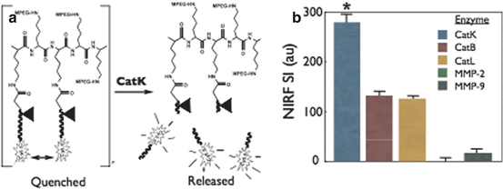

Fig. 4.6
Example of a protease-activatable NIRF molecular imaging biosensor. (a) Schematic of the protected graft copolymer backbone containing a peptide sequence substrate (Gly-His-Pro-Gly-Gly-Pro-Gln-Gly-Lys-Cys-NH2) specific for cathepsin K (CatK) linked to tightly packed nonfluorescent (quenched) NIRF reporters. In the presence of activated CatK, fluorescent probes are released by CatK substrate cleavage to liberate NIRF signaling. (b) In vitro testing with different cathepsin and matrix metalloproteinase (MMP) enzymes demonstrated preferential cleavage of the targeted agent by CatK (*p < 0.05) (Reproduced with permission from Jaffer et al. [31])
4.4.2.2 Stand-Alone In Vivo Intravascular NIRF Sensing
Using the early prototype one-dimensional intravascular NIRF imaging system, cathepsin protease activity was assessed in the balloon-injured atherosclerotic iliac arteries of hypercholesterolemic rabbits [54]. Prosense VM110 injected 24 h prior to NIRF imaging revealed increased cathepsin protease activity at sites of atheroma formation by manual catheter pullback that was confirmed by ex vivo macroscopic fluorescence reflectance imaging (FRI) and matched histopathology (Fig. 4.7). Significantly, NIRF plaque detection was accomplished through flowing blood without the need for vessel flushing of occlusion, demonstrating the advantageous in vivo light transmission properties of NIRF light wavelengths. Normal, healthy rabbits injected with Prosense VM110 and atherosclerotic rabbits injected with a saline control vehicle exhibited minimal tissue NIRF signal consistent with background autofluorescence, thus demonstrating the specificity of this agent for NIRF protease detection. Since the rabbit iliac artery is of similar caliber to a small coronary artery (2.0–2.5 mm), this study demonstrated the feasibility of NIRF catheter detection systems to imaging human coronary plaques.
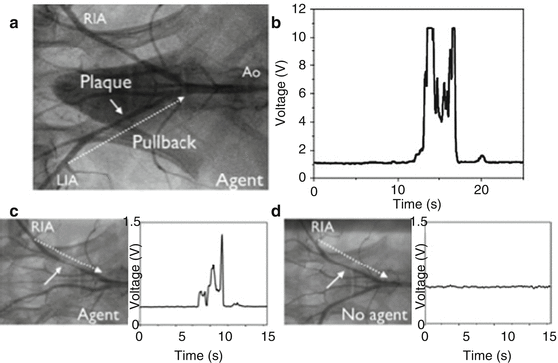

Fig. 4.7
In vivo NIRF sensing of plaque proteolytic activity with the one-dimensional intravascular NIRF catheter. (a) X-ray angiography of the aortoiliac vasculature in a balloon-injured atherosclerotic rabbit demonstrates the presence of left iliac artery (LIA) atherosclerotic plaque (white solid arrow in panels a, c, and d). Twenty-four hours after administration of a protease-activatable NIRF reporter (Prosense VM110), replicate manual NIRF catheter pullbacks from the distal LIA to the aorta (Ao) were performed through the blood without flushing over approximately 20 s each (White dotted arrow indicates catheter pullback trajectory in panels a, c, and d). (b) Strong NIRF protease signal was repeatedly detected at the location of the LIA plaque. (c) Similar findings of elevated plaque NIRF activity were observed in a different rabbit with right iliac artery (RIA) atherosclerosis given Prosense VM110 the day prior, but (d) not in those administered saline control that exhibited only background NIRF signal (Reproduced with permission from Jaffer et al. [54])
Atherosclerotic plaque cathepsin proteolytic activity in the high-cholesterol rabbit model was assessed more comprehensively with the second-generation, two-dimensional NIRF imaging catheter that provides automated pullback with circumferential imaging capabilities [46]. Furthermore, this study extended in vivo NIRF imaging to the larger 3.0–4.0 mm diameter aorta, more consistent with the typical size range of proximal epicardial human coronary arteries. Eight weeks after aortic balloon injury, rabbits were administered i.v. Prosense VM110 or saline control 24 h prior to performing in vivo NIRF imaging. Anatomic plaque information was evaluated by x-ray angiography and grayscale IVUS and then carefully matched to the NIRF data set using side branches and other fiducial markers. Fusion images revealed co-localization of enhanced NIRF cathepsin protease activity with aortic atherosclerotic plaques, demonstrating the ability to identify inflamed plaques in vivo using the second-generation NIRF system (Fig. 4.8). Quantitative analysis of the plaque NIRF signal revealed excellent performance characteristics with significantly greater signal-to-noise (SNR) and target-to-background (TBR) ratios in aortic plaques from rabbits receiving Prosense VM110 compared to saline control (SNR 12.6 vs. 1.3, p = 0.02; TBR 6.3 vs. 1.1, p = 0.02). Ex vivo tissue analysis confirmed the in vivo NIRF findings, including the presence of histological plaque inflammation (i.e., cathepsins and macrophages) in all balloon-injured animals regardless of whether they were administered saline as a control injection with minimal in vivo NIRF signal or Prosense VM110. Notably, immunohistochemistry for plaque cathepsin proteases may be positive in regions without Prosense VM110 NIRF signal, since Prosense VM110 reports only on biologically active cathepsin protease activity rather than total (inactive plus active) protease content.
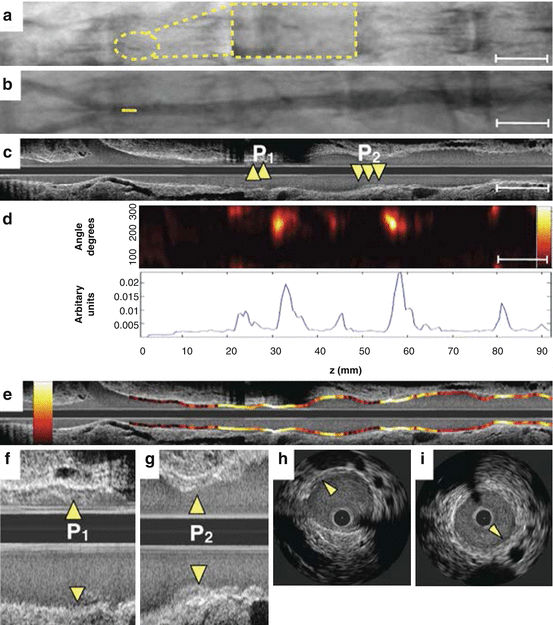

Fig. 4.8
In vivo molecular imaging of atherosclerosis protease inflammation with the two-dimensional intravascular NIRF catheter in a coronary-sized artery. (a) Non-contrast angiography shows placement of the two-dimensional NIRF catheter in the rabbit abdominal aorta (dotted yellow inset highlights radiopaque marker at the catheter tip). (b) Contrast angiography of the aortoiliac vasculature with mild atherosclerotic disease (yellow line indicates catheter tip location). (c) Mild plaques (P1, P2; arrowheads) are observed on the longitudinal IVUS, with more detail on (f, g) higher magnification long view and (h, i) axial IVUS images. (d) Two-dimensional NIRF map (top panel) aligned with angiography and IVUS demonstrates elevated plaque NIRF proteolytic activity, displayed as one-dimensional angle-averaged NIRF signal (bottom panel). (e) NIRF signal superimposed on longitudinal IVUS co-localizes elevated NIRF protease inflammation (yellow/white = high-intensity NIRF signal, red/black = low intensity NIRF signal) to regions of IVUS-defined plaque (Reproduced with permission from Jaffer et al. [46])
4.4.2.3 In Vivo Intravascular NIRF-OFDI
Building on prior experiments with earlier-generation stand-alone NIRF imaging systems, inflamed aortic atherosclerotic plaques in cholesterol-fed, balloon-injured rabbits were assessed with integrated NIRF-OFDI molecular-structural imaging using Prosense VM110 injected 24 h beforehand [55]. OFDI-defined plaques revealed enhanced NIRF cathepsin protease signal that was absent in normal vessel segments. Within a single plaque, heterogeneous NIRF proteolysis was observed at high spatial resolution and precisely mapped to the OFDI microstructure (Fig. 4.9). At histopathology, NIRF-positive aortic plaques exhibited increased macrophage infiltration and cathepsin B expression. By combining exact anatomically matched biological and structural plaque information as demonstrated in this feasibility study, intravascular NIRF-OFDI is poised to inform upon previously unappreciated and inaccessible high-risk atherosclerotic plaque features in vivo such as cysteine protease activity, with the possibility to perform serial imaging studies that evaluate drug treatment effects on plaque inflammation in living subjects. Furthermore, as OFDI signal standard deviation threshold measurements can detect resident plaque macrophages in macrophage-dense lesions [69], ongoing studies are attempting to understand whether adding NIRF imaging of proteolytic activity can identify a subset of the OFDI macrophage population that represent activated or M1-type macrophages.
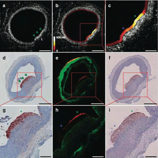

Fig. 4.9
In vivo NIRF-OFDI molecular-structural imaging of atheroma protease activity. (a) OFDI cross-sectional image demonstrates a focal lipid-rich (L) plaque (arrowheads) in an atherosclerotic rabbit aorta associated with (b, c) strong quantitative NIRF protease inflammation (yellow/white). In comparison, areas of normal vessel wall by OFDI have low NIRF signal (red/black). Immunochemistry staining for (d, g) RAM-11 and (f, i) cathepsin B shows dense macrophage and cysteine protease infiltration, respectively, throughout the atheroma. (e, h) Fluorescent microscopy revealed plaque NIRF signal (red) in a similar pattern (i.e., greater NIRF at the green asterisk compared to the blue asterisk) to the matched in vivo NIRF-OFDI axial image from (c) that was distinct from tissue autofluorescence (green). Scale bars, 200 μm (c, g–i) and 500 μm (a, b, d–f) (Reproduced with permission from Yoo et al. [55])
4.4.2.4 NIRF Imaging of Lipid-Rich, Inflamed Plaques with Indocyanine Green
For clinical translation of intravascular NIRF imaging technology, targeted NIRF molecular imaging agents for patient administration must be made available. At present, Prosense VM110 is not approved for human use, and therefore, alternative NIRF inflammation-sensing molecular probes have been pursued to speed clinical translation. Indocyanine green (ICG) is a candidate near-infrared fluorochrome already approved by the Food and Drug Administration (FDA) for intravascular blood flow measurements in ophthalmic retinal imaging and for assessment of cardiac output and hepatic function [70,71]. ICG is an amphiphilic fluorescent dye that binds circulating plasma proteins including atherogenic low-density lipoprotein (LDL) [72] and has been reported to localize within inflamed tissues [73].
Given these promising attributes, ICG was selected for further evaluation of its ability to identify inflamed atheroma and plaque lipid accumulation in vivo with one-dimensional stand-alone NIRF imaging [74]. Eight weeks following aortoiliac balloon injury, hyperlipidemic rabbits were injected with an FDA-approved ICG dose (1.5 mg/kg) prior to in vivo NIRF imaging. Automated pullbacks matched with IVUS for plaque topography revealed locally increased ICG signal in atheroma that was durable for up to 45 min after ICG administration (Fig. 4.10). Ex vivo FRI macroscopically corroborated the in vivo NIRF ICG signal. Detailed fluorescence microscopy and histopathology matched to NIRF and IVUS was then performed to localize the tissue source of ICG plaque signal. Within atheroma, ICG co-localized with lipid (Oil Red O neutral triglyceride staining) and macrophages (RAM-11 antibody). Extending this association further to human tissues, in vitro testing revealed ICG binding to acetylated LDL and ingestion by human macrophages and experimentally derived foam cells, and ex vivo incubation of resected carotid endarterectomy specimens with ICG demonstrated ICG uptake in plaque regions with increased lipid and macrophage content. Therefore, although additional mechanisms of ICG binding to lipid populations and macrophage subsets need to be elucidated, ICG appears to be a promising clinically available NIRF molecular imaging agent for inflamed, lipid-rich atherosclerotic plaques that may accelerate human translation of intravascular NIRF imaging studies.
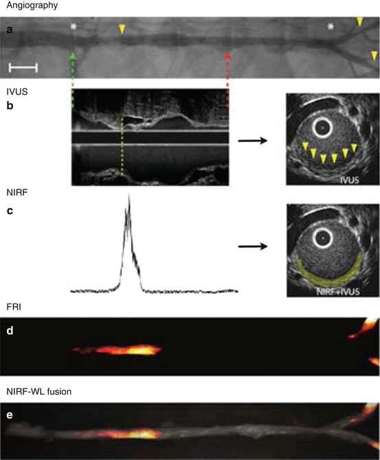

Fig. 4.10
In vivo NIRF sensing of indocyanine green (ICG) uptake in lipid-rich, inflamed plaques with the one-dimensional intravascular NIRF catheter. (a) Contrast angiography shows multiple sites of rabbit aortic and iliac artery atherosclerosis (arrowheads). Automated NIRF catheter pullback was performed between the green and red dotted arrows, and fiducial markers (e.g., renal and iliac artery branch points; asterisks) were used to anatomically register NIRF signal with IVUS for plaque structural characterization. Scale bar, 1 cm. (b) Longitudinal IVUS revealed small plaques (dotted line) that were eccentric on cross-sectional images (arrowheads). (c) Fifteen minutes after injection, in vivo ICG NIRF signal mapped to the location of IVUS atheroma (yellow pseudocolor). (d, e) Ex vivo fluorescence reflectance imaging (FRI) confirmed plaque ICG uptake (fire look-up table) within atherosclerotic segments on white light (WL) fusion images (Reproduced with permission from Vinegoni et al. [74])
4.4.3 Intravascular NIRF Imaging of Proteolytic Activity in Coronary Stents
Coronary stent procedures in the United States alone are performed in greater than one million patients annually [1] and carry measurable risks of future stent thrombosis and stent restenosis [75]. Although occurring relatively infrequently at rates from 0.3 to 4 % per year depending on the patient population studied, stent thrombosis is a major adverse event that often results in sudden cardiac death [76,77]. Even in survivors of stent thrombosis, a 30-day mortality is reported as high as 10–25 %. While generally less catastrophic, stent restenosis is a more common phenomenon (5–20 %), particularly in diabetic patients, and a significant contributor to recurrent angina, myocardial infarction, and repeat invasive procedures [78,79]. While the development of drug-eluting stents (DES) with antiproliferative coatings to antagonize smooth muscle cell ingrowth has diminished stent restenosis, DES heal slower than uncoated bare-metal stents (BMS) thus leaving metal exposed to flowing blood that may trigger local thrombosis [80–82]. Furthermore, the drug itself and/or polymer coating has been implicated in promoting stent struts that lack endothelial coverage, are inflamed, and develop fibrin deposition [83]. Stent restenosis is routinely visualized with IVUS and OCT/OFDI [50,56,84], and stent strut endothelial coverage can be identified with good accuracy by OCT/OFDI given its high-resolution images [85,86]. However, despite these structural guideposts, there is great need to better understand the in vivo pathobiology that predisposes particular stents and patients to stent thrombosis or stent restenosis.
Stay updated, free articles. Join our Telegram channel

Full access? Get Clinical Tree


