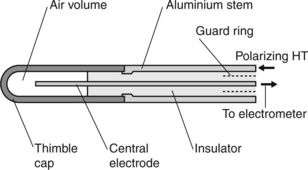
Figure 3.5. The cap is generally made of a low atomic number low-density material such as graphite, although various plastic materials have been used where the plastic has been manufactured to be conductive (e.g. Shonka plastic: [

Figure 3.5 Thimble ionization chamber. Ionization produced within the air volume in the thimble cap is collected by the central electrode. The aluminium stem transmits the polarizing voltage to the thimble cap. The guard ring minimizes charge leakage between the outer (HT) and the inner (signal) elements of the interconnecting cable. A thimble chamber of the Farmer type has the chamber linked to the outside via a venting aperture (not shown).
A potential difference (the polarizing voltage) applied between the outer cap and the inner electrode drives apart any ion pairs produced in the trapped air and prevents ion recombination, but which is insufficiently large to cause ionization of the air itself so that in the absence of ionizing radiation no current flows. A voltage gradient of a few hundred volts per millimetre is generally sufficient for this purpose. In the presence of ionizing radiation, ionization within the air results in the ion pairs being separated, and with the ions of one sign (depending upon the polarity of the polarizing voltage) being collected on the central electrode. The electrometer is generally ‘floating’, in that the input to it can be at any voltage level with respect to ground without this affecting the reading. In use, the aluminium stem is held at ground potential and the electrometer is floated to the level of the polarizing voltage, so that exposed conductive parts carry no electrical risk to operators. This arrangement allows easy reversal of polarizing voltage as required.
When the chamber is introduced into a photon beam, photo-electric and Compton interactions in the walls of the chamber generate electrons that traverse the air cavity, causing ionization of the air. The wall of the thimble must be sufficiently thick to ensure that all the electrons crossing the air cavity originate in the wall and not in the surrounding material. The wall must therefore be at least as thick as the range of the electrons produced by the photon interactions. However, the wall of the chamber will also attenuate the photon beam and this attenuation will need to be taken into account. If the wall is thick, the attenuation will be large. Practical ionization chambers such as the Farmer chamber [
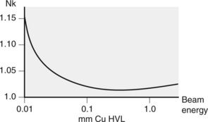
The calibration factor of a thimble chamber varies with photon energy. This calibration corrects for wall attenuation, differences in the mass attenuation coefficient between the wall material and water, and perturbations to the photon beam caused when the chamber (and its associated build-up cap, where applicable) are inserted into a water phantom, thereby displacing water. A typical calibration curve for such an instrument in terms of air kerma for photon beams of kV energies is shown in

Figure 3.6 Typical variation in air-kerma calibration versus beam energy for a thimble chamber for photon beam energies within the kV range – expressed in terms of their half-value layer (see
Stay updated, free articles. Join our Telegram channel

Full access? Get Clinical Tree


