Chapter 6 Mammographic and Ultrasound-Guided Breast Biopsy Procedures
Biopsy of nonpalpable imaging-detected breast lesions is an important part of the breast imaging service. The advantage of percutaneous biopsy is that it can provide a diagnosis with a minimum of patient trauma, and the diagnosis can guide appropriate follow-up, including definitive surgery. If the diagnosis is cancer, the patient can decide on lumpectomy versus mastectomy. Furthermore, patients with invasive cancer can have both tumor excision and axillary lymph node biopsy at the first surgery. This chapter describes percutaneous x-ray– and ultrasound-guided breast needle biopsy techniques, preoperative needle localization, and imaging–pathology correlation. Magnetic resonance imaging (MRI)-guided breast procedures are covered in Chapter 7.
Prebiopsy Patient Workup
Nothing substitutes for complete imaging workup of nonpalpable breast lesions. The radiologist must have the lesion’s location within the breast firmly entrenched in his or her mind to plan an approach that will be successful in biopsying the lesion with safety and accuracy. For mammography, this means visualization of the lesion in craniocaudal and mediolateral orthogonal views (Box 6-1). When the finding is not seen definitively in craniocaudal (CC) and mediolateral views, the radiologist locates the lesion with fine-detail mammographic views, views with skin markers, triangulation, stereotactic targeting, ultrasound, and physical examination. This is to make sure the lesion is real and to determine its location in the breast. For ultrasound, this means the lesion is visualized on orthogonal scans. Do not attempt to biopsy a breast lesion if you do not know whether it is real or if you do not know its location in the breast!
Box 6-1 Requirements for Nonpalpable Breast Lesion Biopsy
Lesion is seen in orthogonal views on mammography or is seen by ultrasound or MRI
Lesion can be accessed with safety and accuracy
Patient can cooperate and hold still during the procedure
Patient is not allergic to medications used in the biopsy procedure
Patient can follow postbiopsy instructions to diminish bleeding and other complications
Patient will comply with postbiopsy imaging or surgical follow-up
For a nonpalpable lesion to be biopsied with safety and accuracy, the patient must be able to cooperate and hold still during the procedure, have no allergies to medications used during the procedure, be able to follow postbiopsy instructions to diminish bleeding and other complications, and be compliant with postbiopsy follow-up (see Box 6-1).
Informed Consent
Informed consent is an important part of any procedure (Box 6-2). For percutaneous needle biopsy, the radiologist informs the patient of the risks, benefits, and alternatives to percutaneous biopsy (e.g., surgical biopsy), as well as the risks and benefits of any alternatives. The most common complication after core or vacuum needle biopsy is hematoma formation, but it is rarely significant. Other rare complications include untoward bleeding (very rarely requiring surgical intervention), infection (with mastitis very rare), pneumothorax, pseudoaneurysm formation, implant rupture, milk fistula (if the patient is pregnant or nursing), and vasovagal reactions (see Box 6-2). The patient is told that later surgical excision will be needed if the biopsy reveals a malignancy, high-risk lesion, or discordant benign lesion, or if the needle biopsy cannot be completed because of technical limitations (see Box 6-2). She is told that the postbiopsy metallic marker may end up in a suboptimal location. The patient is informed about wound management after the biopsy and about when and how to obtain biopsy results.
Box 6-2 Informed Consent and Possible Complications
Preoperative Needle Localization
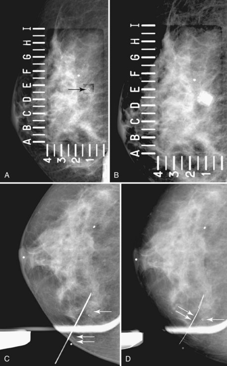
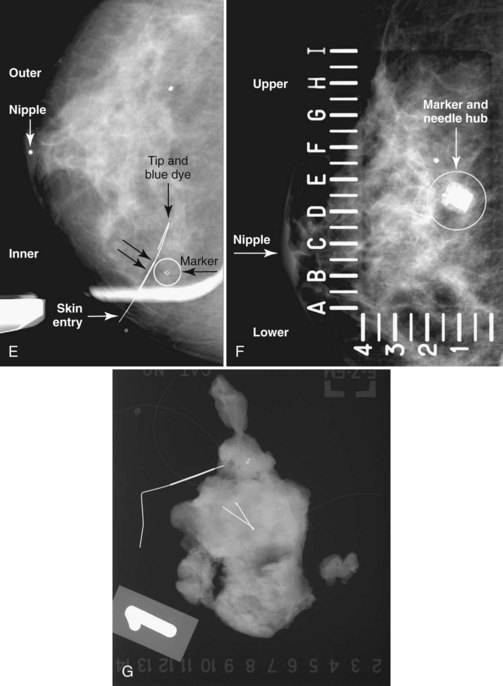
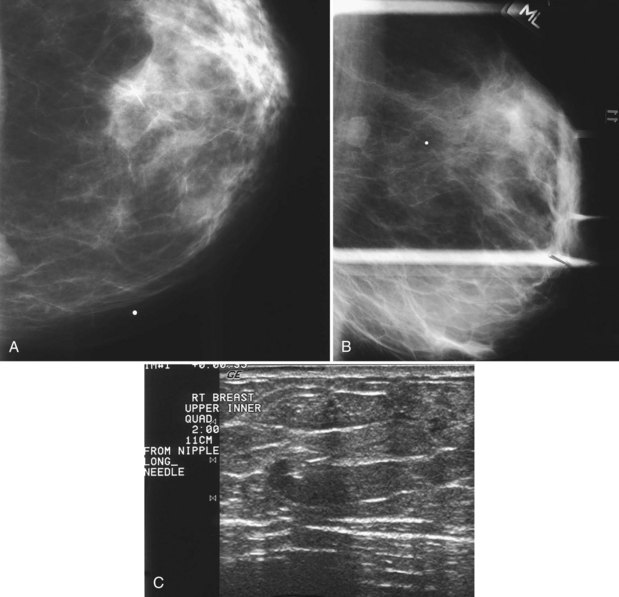
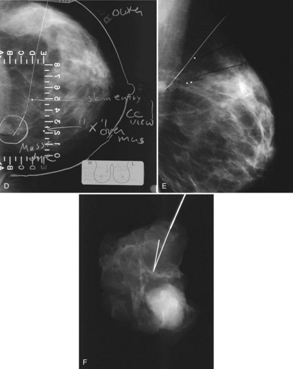
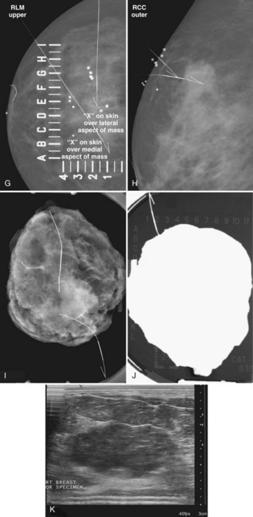
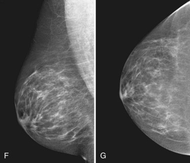
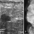
The surgeon uses the wire and mammograms to guide him or her to the lesion and excises the lesion and hookwire. The excised tissue is called a breast specimen. The technologist radiographs the breast specimen. The radiologist reviews the specimen radiograph to see if the lesion and the entire hookwire (with an intact hook) are included (Fig. 6-1A to G).
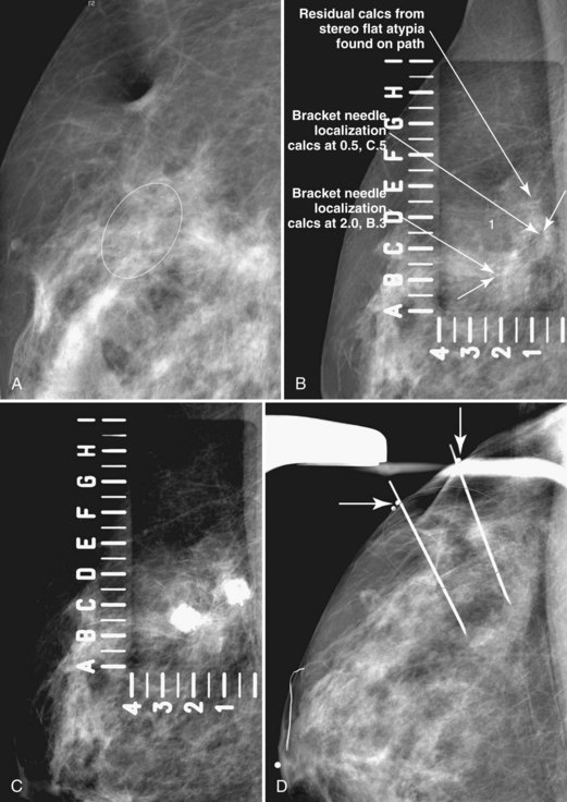
A special scenario regarding needle localizations occurs when surgeons use “bracketing” wires to remove a large area of breast tissue (Fig. 6-2), a scenario that happens when the mass or calcifications extend over too wide an area to be localized by one wire. In this situation, the radiologist places two wires in the breast, with one wire at one end of the lesion and the other wire at the other end of the lesion. The “brackets” help the surgeon remove the lesion between the two wires in toto. These “bracketed” breast specimens should include the two wires and the mass or calcifications between them.
Ultrasound Guidance
Real-time hand-held ultrasound units with a small transducer provide guidance for preoperative needle localization for ultrasonographically detected breast lesions (Fig. 6-3). To do the localization, the patient is placed in the supine position and the radiologist plans the needle path to the lesion. The radiologist rolls or angles the patient on the table until the needle path is directed safely away from the chest wall to prevent pneumothorax. Using sterile technique and under direct ultrasound visualization, the radiologist anesthetizes the skin and inserts a longer needle for deep anesthesia, keeping the entire shaft of the needle, the needle tip, and the target in the same plane. The anesthesia needle can be used as a “trial run” to judge the safety of the needle path and the difficulty of needle insertion. Then the radiologist inserts the preoperative localization needle into the lesion under real-time ultrasound guidance. Blue dye, if used, and a hookwire are inserted.
Specimen Radiography
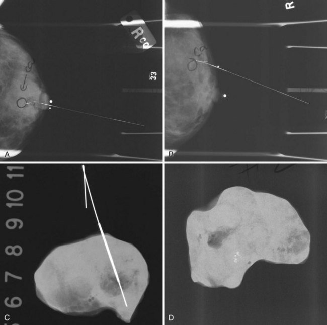
The needle localization procedure is not over until the specimen radiograph is taken by the technologist and reviewed by the radiologist. The radiologist reports whether the specimen contains the entire lesion, how far the lesion is away from the specimen edge, if the lesion was transected, and whether the hookwire, hookwire tip, and any markers are included (Box 6-3). The radiologist then calls these findings to the surgeon in the operating room. If the lesion is not in the specimen, the radiologist directs the surgeon to the expected location by using landmarks in the excised tissue and on the mammogram and waits for a second specimen (Fig. 6-4). If subsequent specimen radiographs still do not contain the lesion, the surgeon may close the breast and obtain a mammogram to determine whether the targeted lesion is still in the breast. The mammogram is usually done a few weeks after the biopsy.
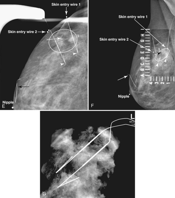
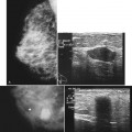
Tissue excised at ultrasound-guided preoperative localizations also undergoes specimen radiography, even if the finding cannot be seen on mammogram. The specimen radiograph may or may not show the ultrasound-localized finding, but will show if the entire hookwire or its tip, as well as any metallic markers, was excised. If the specimen radiograph does not show the ultrasound-localized finding, the radiologist can perform specimen ultrasound to see if the tissue contains the mass (Figs. 6-5 and 6-6).

Pathology Correlation
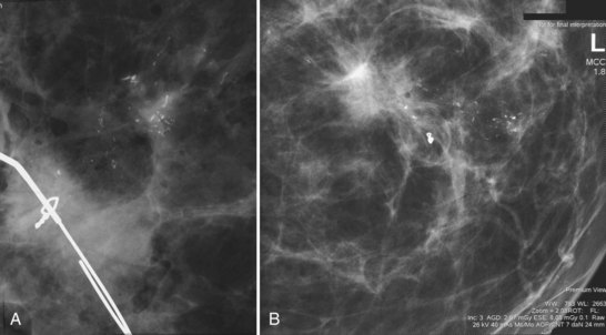
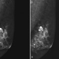
Later, the radiologist reviews the pathology report to see if the pathology reflects what the radiologist expected, based on the lesion’s imaging characteristics. Radiologic–pathologic correlation ensures that the targeted lesion analyzed at pathologic evaluation is concordant with the imaging finding and, specifically, that the pathology report describes a histologic finding that is known to correlate with the imaging findings. For example, if the targeted lesion shows fine pleomorphic calcifications, a diagnosis of malignancy, high-risk lesion, or benign lesion would all be concordant if the targeted calcifications were definitely seen in the specimen radiograph and preferably also on the pathology slides (Fig. 6-7). If the pathology report showed an uncalcified fibroadenoma when the targeted radiographic finding was fine pleomorphic calcifications, the pathologic–radiologic correlation would be discordant, and the case would warrant additional investigation.
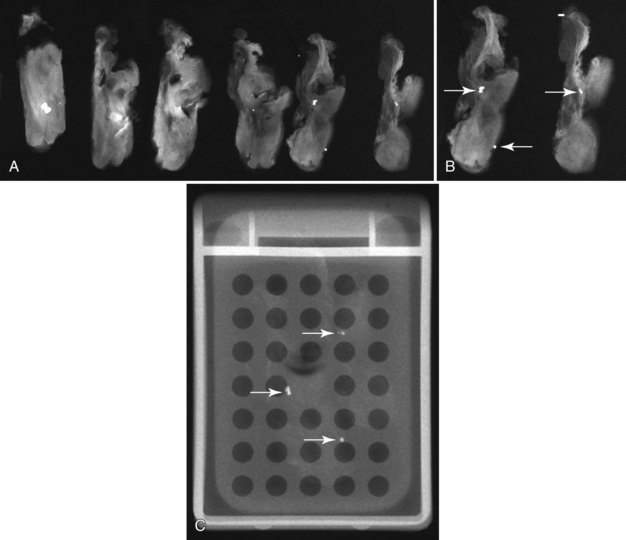
Second, the calcifications may be in the paraffin blocks. During specimen processing, thin breast tissue samples are embedded in paraffin blocks, which are then sliced and placed on slides for staining. Each block is several millimeters thick, but each slide contains only micromillimeters of paraffin and tissue. The calcifications may still be in the block and may never have been placed on a slide for review. A radiograph of the blocks may show the calcifications, and re-sectioning of that particular block will show the calcifications (Fig. 6-8).
Percutaneous Needle Biopsy of Cysts, Solid Masses, or Calcifications
Breast lesions can be classified as cysts, solid masslike lesions (which include true masses, asymmetries, and areas of architectural distortion), and calcifications. Needle types and cyst aspirations are discussed here, followed by needle biopsies guided by palpation, ultrasound, and stereotactic techniques. Needle biopsies guided by MRI are discussed in Chapter 7. This section then discusses core specimen radiography, marker placement, carbon marking, patient safety and comfort after biopsy, complete lesion removal, calcification and epithelial displacement, pathology correlation, high-risk lesions, follow-up of benign lesions, complications, differences between core and vacuum needle biopsies, and patient follow-up, audits, and noncompliance.
Needle Types
The types of biopsy needles used for specific breast lesions and guidance methods vary around the world. A trend toward progressively larger needles and more tissue samples per biopsy site has been noted, especially in the United States. Three main types of needles are used for percutaneous biopsies (Table 6-1). Fine-needle aspiration (FNA) needles, usually 25- to 20-gauge, are used for cyst aspirations and for solid breast masses. The aspirated material requires interpretation by expert cytopathologists. FNA is usually done with ultrasound or palpation guidance with at least four needle passes. FNA is less commonly done in the United States compared to Europe and Asia.
Table 6-1 Needles Used for Percutaneous Breast Biopsies
| Needle Type | Usual Gauge | Biopsy Use |
|---|---|---|
| Fine-needle aspiration | 25- to 20-gauge | Cyst aspiration. Solid mass highly likely to be either benign or malignant |
| Automated large-core | 18- to 14-gauge | Ultrasound-guided biopsy. Uncommon for stereotactic biopsy |
| Directional vacuum-assisted | 14- to 7-gauge | Stereotactic biopsy. Uncommon but growing use for ultrasound-guided biopsy |
Automated large-core (core) needles in 18- to 14-gauge (Fig. 6-9A and B) commonly are used to biopsy masses with ultrasound or palpation guidance. In some facilities, especially outside the United States, core needles are used with stereotactic guidance to biopsy masses or calcifications. An automated large-core biopsy needle obtains a single specimen with each pass of the needle, and 2 to 12 specimens are obtained by firing the needle multiple times. Pathologists who are comfortable interpreting surgically excised breast biopsy tissue can interpret the histologic material obtained.
Directional vacuum-assisted (vacuum) needles (see Fig. 6-9C) are available in 7- to 14-gauge and are used for stereotactic, ultrasound-guided, and MRI-guided biopsies. Depending on the manufacturer, vacuum biopsy can be done with just one needle pass, and multiple specimens are obtained by rotating the collection aperture of the needle to obtain between 6 and 18 specimens. Other directional vacuum-assisted needles obtain single vacuum specimens with each pass, requiring multiple insertions. In some facilities, vacuum biopsies are used to excise benign lesions such as fibroadenomas to avoid the need for surgical excision or imaging follow-up, once the fibroadenoma has been diagnosed by core needle biopsy and adequate sampling.
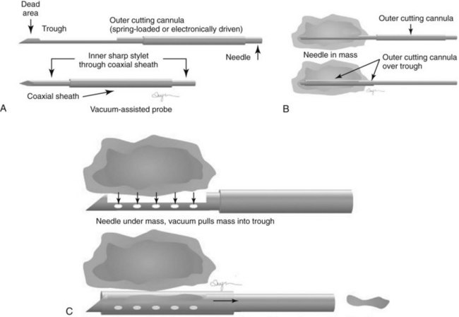
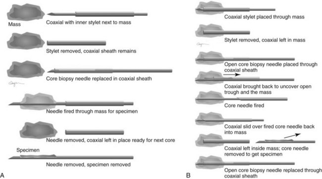
Both single-insertion and multi-insertion needles can be used with or without a coaxial guide (Fig. 6-10A). The coaxial guides are usually used with ultrasound or MRI guidance. The purpose of the coaxial guide is to provide a path to the target that the radiologist can use again and again without retraumatizing the breast tissue. The coaxial device consists of an inner sharp stylet and an outer sheath. The coaxial device is placed through the tissue so that the stylet tip/sheath edge is at or in the lesion. Then the radiologist removes the stylet, leaving a sheath that provides a “tunnel” through the breast tissue directly to the lesion. The radiologist then places the biopsy needle through the sheath into the lesion and takes samples. The radiologist can repeatedly place the biopsy needle through the sheath without having to disturb the surrounding breast tissue. Coaxial biopsies can be done with the sheath near the mass or through the mass (see Fig. 6-10B).
Cyst Aspiration
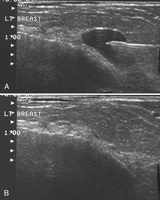
Masses on mammograms often prompt requests for breast ultrasound and cyst aspiration. To do a cyst aspiration the radiologist advances a fine needle into the cyst by palpation or image guidance. If the cyst is tense, fluid wells up into the needle hub. To aspirate the cyst, the radiologist attaches a syringe to the needle and draws fluid into the syringe until no more fluid can be obtained. Cyst aspiration can be done by ultrasound (Fig. 6-11) or, less commonly, by x-ray guidance using a fenestrated compression plate and mammography. If cyst aspiration is done under ultrasound, the radiologist should be able to watch the cyst disappear in real time.
Pneumocystograms are mammograms obtained after the radiologist injects air into a cyst cavity. The pneumocystogram shows the air-filled cyst cavity on the mammogram, enabling the radiologist to make sure that a mass prompting biopsy on the mammogram corresponds to the aspirated cyst and to exclude an intracystic mass. Air is thought to be therapeutic in preventing cyst recurrence (Fig. 6-12). To do a pneumocystogram, the radiologist aspirates the cyst first. Once the fluid has been aspirated completely, the radiologist disengages the syringe while carefully holding the needle tip in the decompressed, flattened cyst cavity. The radiologist attaches an air-filled syringe to the needle, injects a small amount of air into the cyst cavity, takes the needle out, and obtains CC and mediolateral mammograms immediately. A normal pneumocystogram should show an air-filled, thin-walled, round or oval cavity without intracystic solid masses or mural nodules.
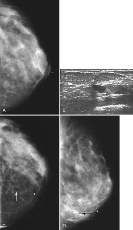
Although radiologists can usually tell if a cyst on ultrasound corresponds to a specific mammographic mass, this correlation can be tricky. When the correlation is unclear and the radiologist has chosen not to do a pneumocystogram, the radiologist orders a postaspiration mammogram to see if the “cyst” disappears. The mass should be gone on the postaspiration mammogram if the aspirated cyst is the mammographic mass. If the mass still shows on the postaspiration mammogram, the mammographic finding is separate from the cyst and needs further investigation (Fig. 6-13).
Ultrasound Guidance
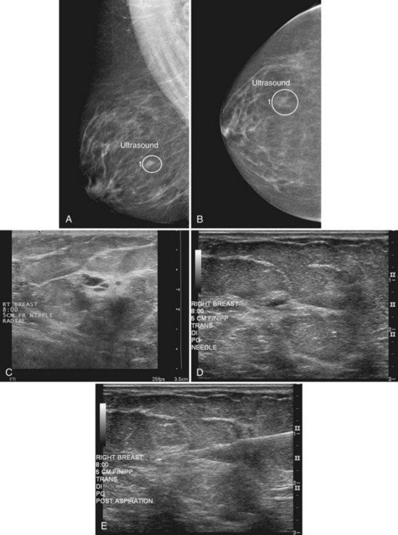
When compared with stereotactic biopsy, ultrasound-guided biopsy has the advantage of using readily available equipment and is fast and cost-effective. The first step in ultrasound-guided biopsy is to find the questioned lesion for biopsy. This commonly occurs when a mass on the mammogram prompts an ultrasound to further characterize the mass and localize it for biopsy. When correlating the mammogram to the ultrasound, the mass can be far away from the chest wall on the mammogram and lie next to the pectoralis muscle on the ultrasound. This occurs because the breast tissue is compressed far away from the chest wall when the patient stands up for the mammogram. On ultrasound, the breast falls dependently onto the chest wall when the patient lies down (Fig. 6-14A).
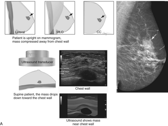
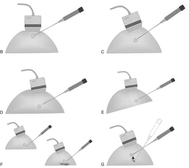
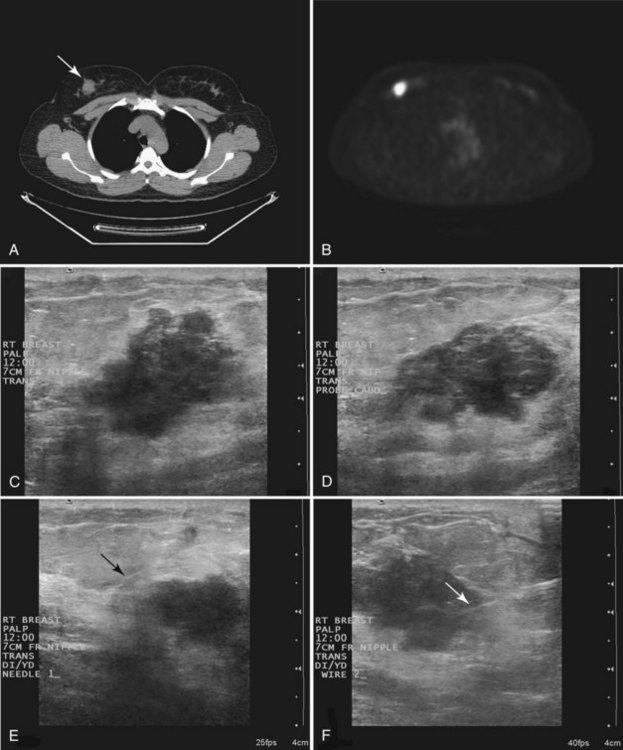
When planning ultrasound-guided needle biopsies, it is important to keep the needle tip away from the chest wall to prevent pneumothorax. Unlike upright preoperative x-ray–guided needle localization or prone stereotactic localization, the ultrasound-guided biopsy is done supine and the needle is not necessarily parallel to the chest wall. Further complicating matters, some core biopsy needles “throw” the cutting trough 2.5 cm further into the tissue beyond the needle tip. Thus, planning a safe ultrasound-guided needle biopsy trajectory must take into account both the needle tip and the needle “throw” trajectory. To plan a safe procedure, the radiologist rolls the patient on the table so that the needle trajectory is as parallel to the chest wall as possible and not at a steep angle aiming toward the lungs. Patient positioning can take some time, but it is worth the few minutes to position the patient accurately to avoid an untoward complication. Another way to keep the needle away from the chest wall is to inject anesthetic underneath the targeted mass to lift it away from the pectoralis muscle. Alternatively, in some cases, the radiologist can stick the biopsy needle tip into the mass and lift it into a safer trajectory before firing the needle (see Fig. 6-14B to G).
For ultrasound-guided FNA, the radiologist introduces a needle in the plane of the transducer axis to show the entire shaft of the needle, its tip, and the lesion. Once the needle is within the lesion, the radiologist aspirates the mass with a vigorous to-and-fro movement to obtain material for cytologic evaluation and then withdraws the needle. At least four passes should be performed; optimally, the material should be analyzed immediately to ensure that adequate cellular material has been obtained for diagnosis. After aspiration, direct pressure is applied to the site (Fig. 6-15).
Related posts:
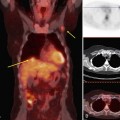 FDG-PET/CT and the Evaluation of Breast Cancer
 Mammography Acquisition: Screen-Film and Digital Mammography, the Mammography Quality Standards Act, and Computer-Aided Detection
 Breast Implants and the Reconstructed Breast
 Breast Ultrasound
 Mammogram Interpretation
 Mammographic and Ultrasound Analysis of Breast Masses
Stay updated, free articles. Join our Telegram channel

Full access? Get Clinical Tree


