Measurement of Absorbed Dose
8.1. Radiation Absorbed Dose
In Chapter 6, the quantity exposure and its unit, the roentgen (C/kg), were discussed. It was then pointed out that exposure applies only to x and γ radiations, is a measure of ionization in air only, and cannot be used for photon energies above about 3 MeV. The quantity absorbed dose has been defined to describe the quantity of radiation for all types of ionizing radiation, including charged and uncharged particles; all materials; and all energies. Absorbed dose is a measure of the biologically significant effects produced by ionizing radiation.
The current definition of absorbed dose, or simply dose, is the quotient  where where  is the mean energy imparted by ionizing radiation to material of mass dm (1). The old unit of dose is rad (an acronym for radiation absorbed dose) and represents the absorption of 100 ergs of energy per gram of absorbing material. is the mean energy imparted by ionizing radiation to material of mass dm (1). The old unit of dose is rad (an acronym for radiation absorbed dose) and represents the absorption of 100 ergs of energy per gram of absorbing material. |
The SI unit for absorbed dose is the gray (Gy) and is defined as:
Thus, the relationship between gray and rad is:
or
Because gray is a larger unit than rad, there is a practical difficulty in switching from rad to grays. For instance, if a patient receives treatments of 175 rad/day, the dose will have to be recorded as 1.75 grays. Because most people prefer numbers without decimals as well as a common resistance to change to the SI units in this country, the adoption of the SI system has been delayed. However, for some, the change is inevitable and the rad is routinely converted into grays. A subunit, centigray (cGy), has often been used as being equivalent to rad.
8.2. Relationship Between Kerma, Exposure, and Absorbed Dose
A. Kerma
The quantity kerma (K) (kinetic energy released in the μedium) is defined as “the quotient of dEtr by dm, where dEtr is the sum of the initial kinetic energies of all the charged ionizing particles (electrons and positrons) liberated by uncharged particles (photons) in a material of mass dm” (1).
The unit for kerma is the same as for dose, that is, J/kg. The name of its SI unit is gray (Gy) and its special unit is rad.
For a photon beam traversing a medium, kerma at a point is directly proportional to the photon energy fluence ψ and is given by:
where  is the mass energy transfer coefficient for the medium averaged over the energy fluence spectrum of photons. As discussed in section 5.4: is the mass energy transfer coefficient for the medium averaged over the energy fluence spectrum of photons. As discussed in section 5.4: |
where  is the averaged mass energy absorption coefficient and is the averaged mass energy absorption coefficient and  is the average fraction of an electron energy lost to radiative processes. Therefore: is the average fraction of an electron energy lost to radiative processes. Therefore: |
A major part of the initial kinetic energy of electrons in low-atomic-number materials (e.g., air, water, soft tissue) is expended by inelastic collisions (ionization and excitation) with atomic electrons. Only a small part is expended in the radiative collisions with atomic nuclei (bremsstrahlung). Kerma can thus be divided into two parts:
where Kcol and Krad are the collision and the radiation parts of kerma, respectively. From Equations 8.8 and 8.9:
and
B. Exposure and Kerma
In Chapter 6, the quantity exposure was defined as dQ/dm where dQ is the total charge of the ions of one sign produced in air when all the electrons (negatrons and positrons) liberated by photons in (dry) air of mass dm are completely stopped in air.
Exposure is the ionization equivalent of the collision kerma in air. It can be calculated from Kcol by knowing the ionization charge produced per unit of energy deposited by photons. The mean energy required to produce an ion pair in dry air is almost constant for all electron energies and has a value of  = 33.97 eV/ion pair (2). If e is the electronic charge (= 1.602 × 10⁻¹⁹C), then = 33.97 eV/ion pair (2). If e is the electronic charge (= 1.602 × 10⁻¹⁹C), then  is the average energy required per unit charge of ionization produced. Since 1 eV = 1.602 × 10⁻¹⁹ J, is the average energy required per unit charge of ionization produced. Since 1 eV = 1.602 × 10⁻¹⁹ J,  = 33.97 J/C. Exposure (X) is given by: = 33.97 J/C. Exposure (X) is given by: |
From Equations 8.10 and 8.12:
The SI unit for exposure is C/kg and the special unit is roentgen (1 R = 2.58 × 10⁻⁴ C/kg).
C. Absorbed Dose and Kerma
The relationship between absorbed dose (D) and the collision part of kerma (Kcol) is illustrated in Figure 8.1 when a broad beam of photons enters a medium. Whereas kerma is maximum at the surface and decreases with depth, the dose initially builds up to a maximum value and then decreases at the same rate as kerma. Before the two curves meet, the electron buildup is less than complete, and:
where β is the quotient of absorbed dose at a given point and the collision part of kerma at the same point.
Because of the increasing range of the electrons, complete electronic equilibrium does not exist within megavoltage photon beams. However, conceptually electronic equilibrium would exist if it were assumed that photon attenuation is negligible throughout the region of interest. Then:
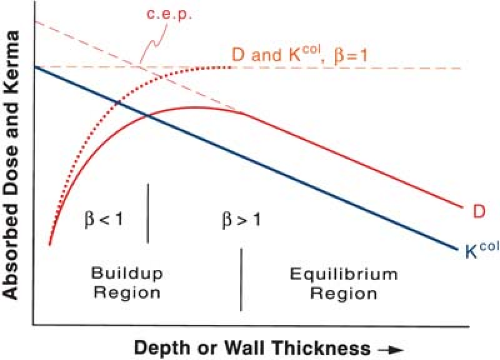 Figure 8.1. Relationship between absorbed dose (D) and collision kerma (Kcol) for a megavoltage photon beam. β is the ratio of absorbed dose to collision kerma. The point designated as c.e.p. is the center of electron production (see text). (From Loevinger R. A formalism for calculation of absorbed dose to a medium from photon and electron beams. Med Phys. 1981;8:1, with permission.) |
At depths greater than the maximum range of electrons, there is a region of quasiequilibrium called the transient electron equilibrium in which:
In the transient equilibrium region, β is greater than unity because of the combined effect of attenuation of the photon beam and the predominantly forward motion of the electrons. Because the dose is being deposited by electrons originating upstream, one can think of a point somewhere upstream at a distance less than the maximum electron range from where the energy is effectively transported by secondary electrons. This point has been called the “center of electron production” (3). Since the effective center of electron production is located upstream relative to the point of interest, the dose is greater than kerma in the region of transient electronic equilibrium.
The relationship between absorbed dose and photon energy fluence ψ at a point where a transient electron equilibrium exists is given by:
Suppose D1 is the dose at a point in some material in a photon beam and another material is substituted of a thickness of at least one maximum electron range in all directions from the point; then D2, the dose in the second material, is related to D1 by:
The factor β has been calculated for 60Co and other photon energies for air, water, polystyrene, carbon, and aluminum (4,5). The results show that the value of β varies with energy, not medium. A fixed value of β = 1.005 has been used for 60Co in conjunction with ion chamber dosimetry (6).
For further details of the relationship between absorbed dose and kerma and its significance in dosimetry, the reader is referred to a paper by Loevinger (4).
8.3. Calculation of Absorbed Dose from Exposure
A. Absorbed Dose to Air
Determination of absorbed dose from exposure is readily accomplished under conditions of electron equilibrium. However, for energies in the megavoltage range, the electron fluence producing absorbed dose at a point is characteristic of photon energy fluence some distance upstream. Consequently, there may be appreciable photon attenuation in this distance. The calculation of absorbed dose from exposure when rigorous electronic equilibrium does not exist is much more difficult, requiring energy-dependent corrections. Therefore, the determination of exposure and its conversion to absorbed dose is practically limited to photon energies up to 60Co. In the presence of charged particle equilibrium (CPE), dose at a point in any medium is equal to the collision part of kerma; that is, β = 1. Dose to air (Dair) under these conditions is given by (see Equation 8.12):
Inserting units:
Since 1 rad = 10-2 J/kg:
From Equation 8.20 it is seen that the roentgen-to-rad conversion factor for air, under the conditions of electronic equilibrium, is 0.876.
B. Absorbed Dose to Any Medium
In the presence of full charged particle equilibrium, the absorbed dose (D) to a medium can be calculated from the energy fluence ψ and the weighted mean mass energy absorption coefficient,(i.e., β = 1 in Equation 8.17):
Suppose ψair is the energy fluence at a point in air and ψmed is the energy fluence at the same point when a material other than air (medium) is interposed in the beam. Then, under conditions of electronic equilibrium in either case, the dose to air is related to the dose to the medium by the following relationship:
where A is a transmission factor that equals the ratio ψmed/ψair at the point of interest.
From Equations 8.19 and 8.22, we obtain the relationship between exposure to air and absorbed dose to a medium:
Again, if we express X in roentgens and Dmed in rad, we have:
The quantity in brackets has frequently been represented by the symbol φmed so that:
where
The quantity φmed or simply the φ factor is sometimes called the roentgen-to-rad conversion factor. As the above equation suggests, this factor depends on the mass energy absorption coefficient of the medium relative to the air. Thus, the f factor is a function of the medium composition as well as the photon energy.
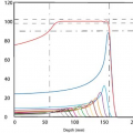
A list of f factors for water, bone, and muscle as a function of photon energy is given in Table 8.1. Since for materials with an atomic number close to that of air, for example, water and soft tissue, the ratio 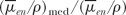 varies slowly with photon energy (∼10% variation from 10 keV and 10 MeV), the f factor for these materials does not vary much over practically the whole therapeutic range of energies. However, bone with a high effective atomic number not only has a much larger f factor between 10 and 100 keV, but also the f factor drops sharply from its maximum value of 4.24 at 30 keV to about 1.0 at 175 keV. This high peak value and rapid drop of the f factor are the result of the photoelectric process for which the mass energy absorption coefficient varies approximately as Z3 and 1/E3 (see Chapter 5). At higher photon energies where the Compton process is the only mode of interaction possible, the f factors are approximately the same for all materials. varies slowly with photon energy (∼10% variation from 10 keV and 10 MeV), the f factor for these materials does not vary much over practically the whole therapeutic range of energies. However, bone with a high effective atomic number not only has a much larger f factor between 10 and 100 keV, but also the f factor drops sharply from its maximum value of 4.24 at 30 keV to about 1.0 at 175 keV. This high peak value and rapid drop of the f factor are the result of the photoelectric process for which the mass energy absorption coefficient varies approximately as Z3 and 1/E3 (see Chapter 5). At higher photon energies where the Compton process is the only mode of interaction possible, the f factors are approximately the same for all materials. |
Strictly speaking, in the Compton range of energies, the f factor varies as a function of the number of electrons per gram. Since the number of electrons per gram for bone is slightly less than for air, water, or fat, the f factor for bone is also slightly lower than for the latter materials in the Compton region of the megavoltage energies. Of course, the f factor is not defined beyond 3 MeV since the roentgen is not defined beyond this energy.
C. Dose Calibration with Ion Chamber in Air
As discussed in Chapter 6, a cavity ion chamber is exposure calibrated against a free-air ion chamber or a standard cavity chamber, under conditions of electronic equilibrium. For lower-energy
radiations such as x-ray beams in the superficial or orthovoltage range, the chamber walls are usually thick enough to provide the desired equilibrium, and therefore, the chamber calibration is provided without a buildup cap. However, in the case of higher-energy radiations such as from cobalt-60, a buildup cap is used over the sensitive volume of the chamber so that the combined thickness of the chamber wall and the buildup cap is sufficient to provide the required equilibrium. This buildup cap is usually made up of acrylic (same as Plexiglas, Lucite, or Perspex) and must be in place when measuring exposure.
radiations such as x-ray beams in the superficial or orthovoltage range, the chamber walls are usually thick enough to provide the desired equilibrium, and therefore, the chamber calibration is provided without a buildup cap. However, in the case of higher-energy radiations such as from cobalt-60, a buildup cap is used over the sensitive volume of the chamber so that the combined thickness of the chamber wall and the buildup cap is sufficient to provide the required equilibrium. This buildup cap is usually made up of acrylic (same as Plexiglas, Lucite, or Perspex) and must be in place when measuring exposure.
Table 8.1 f Factors for Water, Bone, and Muscle Under Conditions of Charged Particle Equilibrium | ||||||||||||||||||||||||||||||||||||||||||||||||||||||||||||||||||||||||||||||||||||||||||||||||||||||||||||||||||||||||||||||||||||||||||
|---|---|---|---|---|---|---|---|---|---|---|---|---|---|---|---|---|---|---|---|---|---|---|---|---|---|---|---|---|---|---|---|---|---|---|---|---|---|---|---|---|---|---|---|---|---|---|---|---|---|---|---|---|---|---|---|---|---|---|---|---|---|---|---|---|---|---|---|---|---|---|---|---|---|---|---|---|---|---|---|---|---|---|---|---|---|---|---|---|---|---|---|---|---|---|---|---|---|---|---|---|---|---|---|---|---|---|---|---|---|---|---|---|---|---|---|---|---|---|---|---|---|---|---|---|---|---|---|---|---|---|---|---|---|---|---|---|---|---|
| ||||||||||||||||||||||||||||||||||||||||||||||||||||||||||||||||||||||||||||||||||||||||||||||||||||||||||||||||||||||||||||||||||||||||||
Suppose the chamber is exposed to the beam (Fig. 8.2A) and the reading M is obtained (corrected for air temperature and pressure, stem leakage, collection efficiency, etc.). The exposure X is then given by:
where Nx is the exposure calibration factor for the given chamber and the given beam quality. The exposure thus obtained is the exposure at point P (center of the chamber-sensitive volume) in free air in the absence of the chamber (Fig. 8.2B). In other words, the perturbing influence of the chamber is removed once the chamber calibration factor is applied.
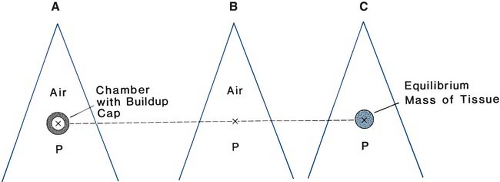 Figure 8.2. A: Chamber with buildup cap is placed in a radiation beam at point P in air and reading M is obtained. B: Exposure in free air at P is calculated using Equation 8.27. C: Dose in free space at P is calculated using Equation 8.28. |
Consider a small amount of soft tissue at point P that is just large enough to provide electronic equilibrium at its center (Fig. 8.2C). The dose at the center of this equilibrium mass of tissue is referred to as the dose in free space. The term dose in free space was introduced by Johns and Cunningham (7), who related this quantity to the dose in an extended tissue medium by means of tissue/air ratios (to be discussed in Chapter 9).
Equation 8.25 can be used to convert exposure into dose in free space, Df.s.:
where Aeq is the transmission factor representing the ratio of the energy fluence at the center of the equilibrium mass of tissue to that in free air at the same point. Thus, Aeq represents the ratio of the energy fluence at point P in Figure 8.2C to that at the same point in Figure 8.2B. For cobalt-60 beam, Aeq is close to 0.99 (7) and its value approaches 1.000 as the beam energy decreases to the orthovoltage range.
D. Dose Measurement from Exposure with Ion Chamber in a Medium
Equations 8.27 and 8.28 provide the basis for absorbed dose calculation in any medium from exposure measurement in air. A similar procedure is valid when the exposure measurement is made with the chamber imbedded in a medium. Figure 8.3A shows an arrangement in which the chamber with its buildup cap is surrounded by the medium and exposed to a photon energy fluence ψb at the center of the chamber (point P). If the energy of the beam incident on the chamber is such that a state of electronic equilibrium exists within the air cavity, then the exposure at point P, with the chamber and the buildup cap removed, is given by:
The exposure thus measured is defined in free air at point P due to energy fluence ψc that would exist at P in the air-filled cavity of the size equal to the external dimensions of the buildup cap (Fig. 8.3B). To convert this exposure to absorbed dose at P in the medium, the air in the cavity must be replaced by the medium (Fig. 8.3C) and the following equation is applied:
or
where Am is the transmission factor for the photon energy fluence at point P when the cavity in Figure 8.3B is replaced by the medium. If ψm is the energy fluence at P in the medium, the factor Am is given by ψm/ψc and has been called a displacement factor.
The above equation is similar to Equation 8.28 except that Am is used instead of Aeq. However, the difference between Am and Aeq is small for a tissue equivalent medium since the equilibrium mass of tissue to which Aeq applies is only slightly smaller than the mass of the medium displaced by a typical small ion chamber with its buildup cap.
An interesting question arises in regard to the necessity of the buildup cap being left on the chamber when making measurements in a medium. If the chamber has been calibrated for
exposure in air with its buildup cap on (to achieve electronic equilibrium) and if a significant part of the cavity ionization is the result of electrons produced in the buildup cap, then replacing the buildup cap with the medium could, in general, alter the chamber reading. This substitution of a layer of medium for the buildup cap could change the electronic and photon fluence incident on the chamber wall by virtue of differences in the composition of the medium and the material of the buildup cap. However, in practical calibration measurements, no significant differences have been observed when exposing the chamber in water with and without the Lucite buildup cap. Day et al. (8) added Perspex sheaths up to 5 mm in thickness to a Baldwin-Farmer ionization chamber irradiated at a depth of 5 cm in a water phantom using radiations from 137Cs to 6 MV. The readings differed by less than 0.5%.
exposure in air with its buildup cap on (to achieve electronic equilibrium) and if a significant part of the cavity ionization is the result of electrons produced in the buildup cap, then replacing the buildup cap with the medium could, in general, alter the chamber reading. This substitution of a layer of medium for the buildup cap could change the electronic and photon fluence incident on the chamber wall by virtue of differences in the composition of the medium and the material of the buildup cap. However, in practical calibration measurements, no significant differences have been observed when exposing the chamber in water with and without the Lucite buildup cap. Day et al. (8) added Perspex sheaths up to 5 mm in thickness to a Baldwin-Farmer ionization chamber irradiated at a depth of 5 cm in a water phantom using radiations from 137Cs to 6 MV. The readings differed by less than 0.5%.
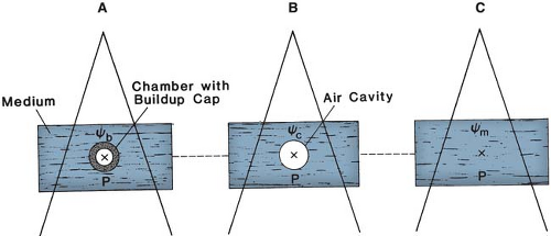 Figure 8.3. A: Chamber with buildup cap with its center at point P in a medium, exposed to a photon beam whose energy fluence is ψb at P. Reading M is obtained. B: Exposure at P in air cavity of size equal to the external dimensions of the buildup cap is calculated. Energy fluence at P is ψc. C: Absorbed dose at point P in the medium is calculated by Equation 8.29. ψm is the energy fluence at P. |
8.4. The Bragg-Gray Cavity Theory
As discussed earlier, calculation of absorbed dose from exposure is subject to some major limitations. For instance, it may not be used for photons above 3 MeV and may not be used in cases where electronic equilibrium does not exist. In addition, the term exposure applies only to x and γ radiations and for that reason methods of section 8.3 are not valid for particle dosimetry. The Bragg-Gray cavity theory, on the other hand, may be used without such restrictions to calculate dose directly from ion chamber measurements in a medium.
According to the Bragg-Gray theory (9,10), the ionization produced in a gas-filled cavity placed in a medium is related to the energy absorbed in the surrounding medium. When the cavity is sufficiently small so that its introduction into the medium does not alter the number or distribution of the electrons that would exist in the medium without the cavity, then the following Bragg-Gray relationship is satisfied:
where Dmed is the absorbed dose in the medium (in the absence of the cavity), Jg is the ionization charge of one sign produced per unit mass of the cavity gas, and  is a weighted mean ratio of the mass stopping power of the medium to that of the gas for the electrons crossing the cavity. The product of Jg ( is a weighted mean ratio of the mass stopping power of the medium to that of the gas for the electrons crossing the cavity. The product of Jg ( ) is the energy absorbed per unit mass of the cavity gas. ) is the energy absorbed per unit mass of the cavity gas. |
The basic Bragg-Gray relationship has been carefully examined by many investigators and several modifications of the theory have been proposed (11,12,13,14). These refinements resulted in more detailed considerations of what is appropriate to use for the mass stopping power ratio in Equation 8.30.
A. Stopping Power
The term stopping power refers to the energy loss by electrons per unit path length of a material (for greater details, see section 14.1). An extensive set of calculated values of mass stopping powers has been published (15,16). As mentioned earlier, to use stopping power ratios in the Bragg-Gray formula, it is necessary to determine a weighted mean of the stopping power ratios for the electron spectrum set in motion by the photon spectrum in the materials concerned. Methods for calculating average stopping powers (S) for photon beams have been published (17). Several authors have worked out the theory of the stopping power ratio for an air-filled cavity in a medium such as water under electron irradiation. A good approximation is provided by the Spencer-Attix formulation (11,18):
where Φ(E) is the distribution of electron fluence in energy and L/r is the restricted mass collision stopping power with Δ as the cutoff energy.
The “primary electrons” (original electrons or electrons generated by photons) give rise to ionization as well as “secondary electrons” or δ rays. The effects of the latter are accounted for in the Spencer-Attix formulation by using an arbitrary energy limit, Δ, below which energy transfers are considered dissipative; that is, the secondary electron of energy less than Δ is assumed to dissipate its energy near the site of its release. Thus, when the integration is performed (Equation 8.31) to obtain the energy deposited in the cavity by the electron fluence, the lower energy limit should be Δ, greater than zero. For ion chambers it must have a value of the order of the energy of an electron that will just cross the cavity. The value of Δ for most cavity applications in ion chambers will lie between 10 and 20 keV.
The Spencer-Attix formulation of the Bragg-Gray cavity theory uses the following relationship:
where  is the average restricted mass collisional stopping power of electrons. Tables A.1, A.2, A.3, A.4 and A.5 in the Appendix give is the average restricted mass collisional stopping power of electrons. Tables A.1, A.2, A.3, A.4 and A.5 in the Appendix give  for various media and various photon and electron energies. for various media and various photon and electron energies. |
B. Chamber Volume
The quantity Jg in Equation 8.32 can be determined for a chamber of known volume or known mass of air in the cavity if the chamber is connected to a charge-measuring device. However, the chamber volume is usually not known to an acceptable accuracy. An indirect method of measuring Jair is to make use of the exposure calibration of the chamber for 60Co γ-ray beam. This in effect determines the chamber volume.
Consider an ion chamber that has been calibrated with a buildup cap for 60Co exposure. Suppose the chamber with this buildup cap is exposed in free air to a 60Co beam and that a transient electronic equilibrium exists at the center of the chamber. Also assume initially that the chamber wall and the buildup cap are composed of the same material (wall). Now, if the chamber (plus the buildup cap) is replaced by a homogeneous mass of wall material with outer dimensions equal to that of the cap, the dose Dwall at the center of this mass can be calculated as follows:
where  is the ratio of electron fluence at the reference point P (center of the cavity) with chamber cavity filled with wall material to that with the cavity filled with air. This correction is applied to the Bragg-Gray relation (Equation 8.29) to account for change in electron fluence. is the ratio of electron fluence at the reference point P (center of the cavity) with chamber cavity filled with wall material to that with the cavity filled with air. This correction is applied to the Bragg-Gray relation (Equation 8.29) to account for change in electron fluence. |
As discussed by Loevinger (4)1, Φ in the above equation can be replaced by ψ, provided a transient electron equilibrium exists throughout the region of the wall from which secondary electrons can reach the cavity. Therefore:
If Dair is the absorbed dose to air that would exist at the reference point with the chamber removed and under conditions of transient electronic equilibrium in air, we get from Equation 8.18:
where  is the ratio that corrects for the change in photon energy fluence when air replaces the chamber (wall plus cap). is the ratio that corrects for the change in photon energy fluence when air replaces the chamber (wall plus cap). |
From Equations 8.34 and 8.35, we get:
Also, Dair (under conditions of transient electronic equilibrium in air) can be calculated from exposure measurement in a 60Co beam with a chamber plus buildup cap, which bears an exposure calibration factor Nx for 60Co γ rays:
where k is the charge per unit mass produced in air per unit exposure (2.58 × 10⁻⁴ C kg-1 R-1), M is the chamber reading (C or scale division) normalized to standard atmospheric conditions, Aion is the correction for ionization recombination under calibration conditions, and Pion is the ionization recombination correction for the present measurement.
Standard conditions for Nx are defined by the standards laboratories. The National Institute of Standards and Technology (NIST) specifies standard conditions as temperature at 22°C and pressure at 760 mm Hg. Since exposure is defined for dry air, humidity correction of 0.997 (for change in  with humidity) is used by the NIST, which can be assumed constant in the relative humidity range of 10% to 90% for the measurement conditions with minimal error (19). Thus, the user does not need to apply additional humidity correction as long as it is used for dry air. with humidity) is used by the NIST, which can be assumed constant in the relative humidity range of 10% to 90% for the measurement conditions with minimal error (19). Thus, the user does not need to apply additional humidity correction as long as it is used for dry air. |
From Equations 8.36 and 8.37:
The product  equals equals  , which represents a correction for the change in Jair due to attenuation and scattering of photons in the chamber wall and buildup cap. This factor has been designated as Awall in the American Association of Physicists in Medicine (AAPM) protocol (6). Thus, Equation 8.38 becomes: , which represents a correction for the change in Jair due to attenuation and scattering of photons in the chamber wall and buildup cap. This factor has been designated as Awall in the American Association of Physicists in Medicine (AAPM) protocol (6). Thus, Equation 8.38 becomes: |
Now consider a more realistic situation in which the chamber wall and buildup cap are of different materials. According to the two-component model of Almond and Svensson (20), let α be the fraction of cavity air ionization owing to electrons generated in the wall and the remaining (1 – α) from the buildup cap. Equation 8.39 can now be written as:
or
where Aa is the quantity in the brackets of Equation 8.40.
The fraction α has been determined experimentally by dose buildup measurements for various wall thicknesses (Fig. 8.4). In addition, it has been shown (21) that α is independent of wall composition or buildup cap, as long as it is composed of low-atomic-number material.
Since Jair is the charge produced per unit mass of the cavity air, we have:
where Vc is the chamber volume and rair is the density of air normalized to standard conditions. Comparing Equations 8.40 and 8.41, we have:
C. Effective Point of Measurement
C.1. Plane Parallel Chambers
Since the front plane (toward the source) of the air cavity is flat and is exposed to a uniform fluence of electrons, the point of measurement
is at the front surface of the cavity. This would be strictly true if the electrons were monodirectional and forward directed, perpendicular to the cavity face. If a significant part of the cavity ionization is caused by back-scattered electrons, the point of measurement will shift toward the center. If the plane-parallel chamber has a small plate separation and the electron fluence is mostly forward directed, it is reasonable to assume that the point of measurement is the front surface of the cavity.
is at the front surface of the cavity. This would be strictly true if the electrons were monodirectional and forward directed, perpendicular to the cavity face. If a significant part of the cavity ionization is caused by back-scattered electrons, the point of measurement will shift toward the center. If the plane-parallel chamber has a small plate separation and the electron fluence is mostly forward directed, it is reasonable to assume that the point of measurement is the front surface of the cavity.
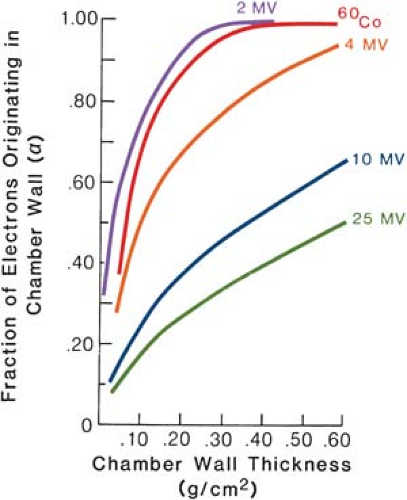 Figure 8.4. The fraction, α, of cavity ionization due to electrons generated in the chamber wall, plotted as a function of wall thickness. (From Lempert GD, Nath R, Schulz RJ. Fraction of ionization from electrons arising in the wall of an ionization chamber. Med Phys. 1983;10:1, with permission.) |
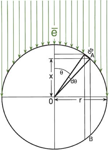 Figure 8.5. Diagram to illustrate the determination of effective point of measurement for a cylindrical chamber exposed to a unidirectional electron beam. |
C.2. Cylindrical Chambers
Electrons (from an electron beam or generated by photons) transversing a cylindrical chamber of internal radius r will enter the sensitive volume of the chamber (air cavity) at different distances from the center of the chamber. Dutreix and Dutreix (22) showed that theoretically the point of measurement for a cylindrical chamber in a unidirectional beam is displaced by 0.85r from the center and toward the source. Derivation of this value is instructive in understanding the concept and is, therefore, presented here.
Figure 8.5 shows a cross section of a cylindrical chamber exposed to a parallel, uniform, and forwardly directed fluence Φ of electrons. For an electron entering the chamber at point A, the point of measurement is at a distance X above the center. Considering electrons entering the chamber at point A, the effective point of measurement is influenced by the number of electrons entering through a surface area ds at A of the chamber and the track length of these electrons in the cavity. Thus, the effective point of measurement, Xeff, can be determined by weighting the displacement X by the number of electrons (Φ·ds cos u) entering the chamber and the track length (2X):
Substituting X = r cos u and ds = rdu:
The above theoretical result is modified under actual irradiation conditions as some of the electrons enter the chamber at oblique angles.
The shift in the point of measurement takes place because of the cylindricality of the chamber cavity. If there is a gradient of electron fluence across the cavity (as in the exponential falloff of the depth dose curve), a shift in the point of measurement will result in a “gradient correction” to the dose measured at a point corresponding to the center of the chamber (to be discussed).
8.5. Calibration of Megavoltage Beams: TG-21 Protocol
A. Cavity-Gas Calibration Factor (Ngas)
The AAPM TG-21 protocol (6) for absorbed dose calibration introduced a factor (Ngas) to represent calibration of the cavity gas in terms of absorbed dose to the gas in the chamber per unit charge or electrometer reading. For an ionization chamber containing air in the cavity and exposed to a 60Co γ ray beam:2
From Equations 8.40 and 8.45:
As seen in Equation 8.46, Ngas is derived from Nx, the exposure calibration for the chamber, and other chamber-related parameters, all determined for the calibration energy (e.g., 60Co). Once Ngas is determined, the chamber can be used as a calibrated Bragg-Gray cavity to determine absorbed dose from photon and electron beams of any energy and in phantoms of any composition.
It may be noted that in Equation 8.46 the term in the big brackets is presented differently from the AAPM protocol. This difference remains unexplained, but the two expressions give the same value to within 0.05% in the limit of α = 0 and α= 1 (24).
Ngas is unique to each ionization chamber, because it is related to the volume of the chamber. From Equations 8.42 and 8.46, using  = 33.97 J/C and rair = 1.197 kg/m3 at standard conditions = 33.97 J/C and rair = 1.197 kg/m3 at standard conditions |
(22°C and 1 atm):
As an example, if the volume of the chamber is 0.600 cm3, its Ngas will be 4.73 × 10⁷ Gy/C, as calculated from Equation 8.47. It must be realized, however, that the volume is not exactly the nominal volume associated with commercial chambers. The latter is usually an approximate value used for designating chamber sensitivity.
B. Chamber as a Bragg-Gray Cavity
In this section, we will discuss the application of the Spencer-Attix formulation of the Bragg-Gray cavity theory to the problem of absorbed dose determination to a medium using a heterogeneous chamber, that is, a chamber with wall material different from the surrounding medium. It will be assumed that the chamber with its buildup cap has been calibrated for cobalt-60 exposure and this provides the basis for the determination of Ngas, as discussed in the previous section.
B.1. Photon Beams
Suppose the chamber, with its buildup cap removed (it is recommended not to use a buildup cap for in-phantom dosimetry), is placed in a medium and irradiated by a photon beam of given energy. If M is the charge measured, the absorbed dose (Dair) to cavity air, at a point at the center of the cavity (P), is given by:
where Pion is a correction factor for ion recombination losses.
Dose to medium (Dmed) is given by the Bragg-Gray relationship using the Spencer-Attix formulation. Using AAPM protocol (6) notation and substituting “air” for “gas” in the chamber:
where Prepl is a replacement factor that corrects for perturbation in the electron and photon fluences at point P as a result of insertion of the cavity in the medium and Pwall is a factor that accounts for perturbation caused by the wall being different from the medium.
In general, Equation 8.49 is valid for any energy and any depth in the medium (irrespective of the state of electronic equilibrium) provided Prepl and Pwall are known for the measurement conditions. Although these correction factors are quite small (usually <1%) for typical photon dosimetry conditions, their determination is complex, especially under conditions of nonequilibrium. The AAPM values for Prepl and Pwall have been derived with the chamber irradiated under the conditions of transient electronic equilibrium (on the descending exponential part of the depth dose curve). The following derivation of these factors will initially assume these conditions but later will consider their applicability to nonequilibrium situations.
Suppose the chamber is positioned at a depth in the medium at which transient electronic equilibrium exists. If the chamber wall is thick enough so that the electrons crossing the cavity arise entirely from photons interacting with the wall material, we have:
where Dwall is the dose at point P when cavity air is replaced by the wall material and  is the ratio that corrects for the difference in the photon energy fluence at point P when air cavity is replaced by the wall material. The rationale for using is the ratio that corrects for the difference in the photon energy fluence at point P when air cavity is replaced by the wall material. The rationale for using  as the perturbation correction factor in this case has been discussed by Loevinger (4). as the perturbation correction factor in this case has been discussed by Loevinger (4). |
Dose to point P if the chamber is replaced by the medium is given by:
or
where  is the ratio that corrects for the change in photon energy fluence when medium replaces the wall material in a volume that corresponds to the entire chamber (wall plus cavity). is the ratio that corrects for the change in photon energy fluence when medium replaces the wall material in a volume that corresponds to the entire chamber (wall plus cavity). |
Now if all the electrons crossing the cavity arise from the medium, we effectively have a case of a chamber with medium equivalent wall. Then, under conditions of transient electronic equilibrium:
For a given chamber, suppose a fraction α of the cavity ionization is contributed by electrons from the chamber wall and the remainder (1 – α) by electrons from the medium; then, dose to air in the chamber is given by:
where Dair(wall) and Dair(med) are derived from Equations 8.52 and 8.53. Thus:
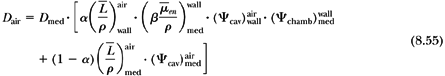
By rearranging Equation 8.55:
The product term  may be equated to may be equated to  , a factor that accounts for change in photon energy fluence when wall is replaced by medium. , a factor that accounts for change in photon energy fluence when wall is replaced by medium. |
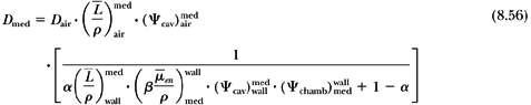
Then, from Equations 8.48, 8.49, and 8.56:
where
and
Since β does not change significantly with change in material composition (4), the ratio  can be equated to 1. Equation 8.59 becomes: can be equated to 1. Equation 8.59 becomes: |
Equation 8.60 as an expression for Pwall differs from the one in the AAPM protocol, since the components α and (1 – α) are applied to Dair before calculating Dmed (see Equation 8.52). Rogers (24) has pointed out that the AAPM expression for Pwall, which assigns the two components to Dmed directly, is not theoretically justified. However, this does not give rise to any significant differences in the results. Also, the previous expression includes  , which appears from the theoretical considerations presented here. This factor may approximately be equated to , which appears from the theoretical considerations presented here. This factor may approximately be equated to 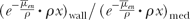 where x is the wall thickness. where x is the wall thickness. |
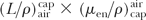
An alternative approach to deriving Prepl is to define Dair = M · Ngas as the dose to air of an infinitesimally small air cavity located in the medium at a point I′, corresponding to the chamber’s effective point of measurement (see section 8.4C). Because Prepl for this small cavity can be assumed as 1, we have:
Dose to medium at point P corresponding to the center of the chamber will then be:
Therefore, Prepl for the chamber under consideration is:
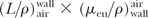
This derivation assumes that Prepl arises as a result of the displacement of the effective point of measurement of the chamber, and its value depends on the depth dose gradient. This point has been discussed by Khan (25). For a cylindrical chamber, Prepl can be calculated from the following equation:
where D(δ) is the dose at depth d, hr is the displacement correction, and r is the radius of the cavity. h for photon beams is taken to be equal to 0.6. Equation 8.64 shows that Prepl depends not only on energy, but also on the depth of measurement.
The AAPM TG-21 protocol recommends Prepl factors based on the semiempirical values of Cunningham and Sontag (26). These values are applicable only if a measurement is made at a point on the descending exponential part of the depth dose curve. Moreover, as pointed out by Rogers (24), Cunningham and Sontag’s values pertain to the outer diameter of the chamber instead of the inner diameter presented in the protocol data.
The use of chamber displacement correction to determine Prepl (Equation 8.64) is useful not only in calibration, but also in correcting the entire depth dose distribution. In the latter case, instead of calculating Prepl at individual points, the depth dose (or depth ionization) curve as a whole is shifted toward the surface by a distance hr.
B.2. Electron Beams
When a chamber, with its buildup cap removed, is placed in a medium and irradiated by an electron beam, it is usually assumed that the chamber wall does not introduce any perturbation of the electron fluence. This assumption is considered valid for thin-walled (≤0.5 mm) chambers composed of low-atomic-number materials (e.g., graphite, acrylic) (15,27). Thus, the Bragg-Gray relationship can be applied without the wall perturbation correction (i.e., Pwall = 1).
For an electron beam of mean energy Ēz at depth Z of measurement:
or in the notation of the AAPM protocol (6):
where Prepl is a replacement correction factor to account for three effects: (a) the in-scatter effect, which increases the fluence in the cavity since electron scattering out of the cavity is less than that expected in the intact medium; (b) the obliquity effect, which decreases the fluence in the cavity because electrons travel relatively straight in the cavity instead of taking oblique paths as they would owing to larger-angle scattering in the medium; and (c) displacement in the effective point of measurement, which gives rise to a correction if the point of measurement is on the sloping part of the depth dose curve. The first two effects may be grouped into a fluence correction while the third is called the gradient correction.
The AAPM TG-21 protocol (6) recommends that the electron beam calibration be made at the point of depth dose maximum. Because there is no dose gradient at that depth, the gradient correction is ignored. Prepl, then, constitutes only a fluence correction. Table 8.2 gives Prepl for
cylindrical chambers as a function of mean electron energy at the depth of measurement and the inner diameter of ion chamber. These values were measured by Johansson et al. (27).
cylindrical chambers as a function of mean electron energy at the depth of measurement and the inner diameter of ion chamber. These values were measured by Johansson et al. (27).
Table 8.2 Electron Fluence Perturbation Factors for Ion Chambers | |||||||||||||||||||||||||||||||||||||||||||||||||
|---|---|---|---|---|---|---|---|---|---|---|---|---|---|---|---|---|---|---|---|---|---|---|---|---|---|---|---|---|---|---|---|---|---|---|---|---|---|---|---|---|---|---|---|---|---|---|---|---|---|
| |||||||||||||||||||||||||||||||||||||||||||||||||
As discussed in an AAPM report (28), a depth ionization curve can be converted into a depth dose curve using Equation 8.66. The parameters  and Prepl are both energy or depth dependent. The gradient correction, however, is best handled by shifting the point of measurement toward the surface through a distance of 0.5r (28,29). For well-designed plane-parallel chambers with adequate guard rings, both fluence and gradient corrections are ignored (i.e., Prepl = 1); the point of measurement is at the front surface of the cavity. and Prepl are both energy or depth dependent. The gradient correction, however, is best handled by shifting the point of measurement toward the surface through a distance of 0.5r (28,29). For well-designed plane-parallel chambers with adequate guard rings, both fluence and gradient corrections are ignored (i.e., Prepl = 1); the point of measurement is at the front surface of the cavity. |
C. Dose Calibration Parameters
Absorbed dose calibration of a clinical radiation beam requires that a nationally or internationally approved protocol be followed. This is important not only to ensure acceptable dosimetric accuracy in patient treatments, but also to provide consistency of dosimetric data among institutions that provide radiotherapy. In the previous section, derivation of a dose calibration formalism recommended by the AAPM TG-21 protocol was presented. In the process, a few discrepancies or inconsistencies in the protocol were noted. However, their overall impact on the accuracy of the protocol is not serious enough to recommend variance from the protocol. An AAPM task group was formed that was charged with the task of carefully reviewing the protocol and making necessary revisions or updates. In the meantime the user was advised to follow the protocol as it stood. A new protocol, TG-51, was introduced by the AAPM in 1999 (to be discussed later).
As a summary to the previous section, pertinent calibration parameters of the TG-21 protocol are outlined below with a brief description of their function and evaluation.
C.1. Chamber Calibration Factor, Nx
Ion chamber exposure calibration factor (R/C or R/scale division) for 60Co γ rays is provided by the NIST or an Accredited Dosimetry Calibration Laboratory (ADCL). This factor—which is characteristic of the chamber, its volume, and its buildup cap—is determined by exposing it to a 60Co beam of known exposure rate and/or comparing its response with a chamber of known exposure calibration factor for 60Co.
At the NIST, specially constructed spherical, graphite ionization chambers of known volume are used to calibrate the cobalt beam in terms of exposure rate. Details of the procedure are given by Loftus and Weaver (3).
NX provided by the U.S. calibration laboratories is normalized to 22°C and 760 mm Hg. Calibration of the electrometer (device to measure ionization charge), if detached, is provided separately.
Exposure measured in a cobalt-60 beam is given by:
where X is the exposure at a point corresponding to the center of the chamber when the chamber is not there, M is the reading corrected for temperature and pressure, and Nel is the electrometer calibration factor, if separate from the chamber. The above equation functionally defines Nx.
C.2. Cavity-Gas Calibration Factor, Ngas
Cavity-gas calibration factor (Gy/C or Gy/scale division) is calculated from Nx and other parameters as discussed earlier. It is defined as dose to the gas in the chamber per unit charge or electrometer reading. Dgas is simply given by  where Jgas is the charge per unit mass of cavity gas and where Jgas is the charge per unit mass of cavity gas and  is the average energy expended per unit charge of ionization produced in the gas. Since mass of air in the cavity or chamber volume is not accurately known, one has to determine this volume indirectly from Nx (Equation 8.46). However, it may be pointed out that Ngas is independent of all properties of the chamber except its cavity volume (Equation 8.47). If Ngas is not provided by the calibration laboratory, the user is required to calculate it. Table 8.3 gives ratios of Ngas/Nx for a number of commercially available chambers. It is seen that Ngas/Nx does not vary greatly between commonly used chambers. However, the user must follow the protocol to calculate Ngas for the given chamber and use Table 8.3 for comparison. Normally, chambers are recalibrated every 2 years and Ngas is calculated at each new calibration of the chamber. is the average energy expended per unit charge of ionization produced in the gas. Since mass of air in the cavity or chamber volume is not accurately known, one has to determine this volume indirectly from Nx (Equation 8.46). However, it may be pointed out that Ngas is independent of all properties of the chamber except its cavity volume (Equation 8.47). If Ngas is not provided by the calibration laboratory, the user is required to calculate it. Table 8.3 gives ratios of Ngas/Nx for a number of commercially available chambers. It is seen that Ngas/Nx does not vary greatly between commonly used chambers. However, the user must follow the protocol to calculate Ngas for the given chamber and use Table 8.3 for comparison. Normally, chambers are recalibrated every 2 years and Ngas is calculated at each new calibration of the chamber. |
Table 8.3 Ratios of Ngas/NX for Commercially Available Chambers | ||||||||||||||||||||||||||||||||||||||||||||||||||||||||||||||||||||||||||||||||||||||||||||||||||||||||||||||||||||||||||||||||||||||||||||||||||||||||||||||||||||||||||||||
|---|---|---|---|---|---|---|---|---|---|---|---|---|---|---|---|---|---|---|---|---|---|---|---|---|---|---|---|---|---|---|---|---|---|---|---|---|---|---|---|---|---|---|---|---|---|---|---|---|---|---|---|---|---|---|---|---|---|---|---|---|---|---|---|---|---|---|---|---|---|---|---|---|---|---|---|---|---|---|---|---|---|---|---|---|---|---|---|---|---|---|---|---|---|---|---|---|---|---|---|---|---|---|---|---|---|---|---|---|---|---|---|---|---|---|---|---|---|---|---|---|---|---|---|---|---|---|---|---|---|---|---|---|---|---|---|---|---|---|---|---|---|---|---|---|---|---|---|---|---|---|---|---|---|---|---|---|---|---|---|---|---|---|---|---|---|---|---|---|---|---|---|---|---|---|
| ||||||||||||||||||||||||||||||||||||||||||||||||||||||||||||||||||||||||||||||||||||||||||||||||||||||||||||||||||||||||||||||||||||||||||||||||||||||||||||||||||||||||||||||

Related posts:

Stay updated, free articles. Join our Telegram channel

Full access? Get Clinical Tree


