Proton Beam Therapy
26.1. Basic Physics
A. Nature of the Particle
According to the Big Bang Theory, hydrogen was the first element to form in the universe (∼100 seconds after the creation of the universe about 13.7 billion years ago). Proton is the nucleus of the hydrogen atom. It carries a unit positive charge (1.6 × 10⁻¹⁹ Coulombs) and has a mass of 1.6 × 10⁻²⁷ kg (∼1,840 times the mass of electron).
Proton has long been considered as a fundamental particle of nature—an indivisible elementary constituent of matter. However, according to the current theory of fundamental particles—the Standard Model—proton has a substructure (see Chapter 1). It consists of three quarks (two up and one down) held together by gluons. Proton is the most stable particle (half-life of >1032 years) and decays into a neutron, a positron, and a neutrino.
The existence of proton was first demonstrated by Ernest Rutherford in 1919. E. O. Lawrence built the first cyclotron in 1930 and Robert Wilson at Harvard University made the first proposal in 1946 that accelerated protons should be considered for radiation therapy. Tobias and his colleagues at Lawrence Berkeley Laboratory first treated patients with protons in 1955. As of 2008, about 25 facilities worldwide are using proton beams for radiotherapy.
B. Interactions
As protons travel through a medium, they interact with atomic electrons and atomic nuclei of the medium through Coulomb force. Rare collisions with atomic nuclei causing nuclear reactions are also possible.
Interactions mediated by Coulomb force are (a) inelastic collisions with atomic electrons in which protons lose part of their kinetic energy to produce ionization and excitation of atoms, thereby resulting in absorbed dose; bremsstrahlung interactions with nuclei are possible but negligible; and (b) elastic scattering without loss of energy. Nuclear scattering is the main contributor to multiple Coulomb scattering of protons.
Compared to the electron beams, the proton beams (because of having heavier charged particles) scatter through much smaller angles. As a result, proton beams have a sharper lateral distribution than the electron or photon beams.
Mass stopping power (energy loss per unit path length in g/cm2) for protons is greater in low-atomic-number (Z) materials than in high-Z materials. Therefore, on a per g/cm2 basis, low-Z materials are more effective in slowing down protons. On the other hand, high-Z materials scatter protons through larger angles than the low-Z materials. Thus, if we want to scatter a beam with minimum loss of energy (principle of scattering foils), we should use high-Z materials, and if we want to decrease proton energy with minimum scattering, we should use low-Z materials. Accordingly, through a combination of high-Z and low-Z materials, we can control scattering and reduction in beam energy.
Head-on collisions with nuclei to produce nuclear reactions are also possible but rare. The product of such a collision is an excited nucleus, secondary protons, neutrons, and, in some cases, α particles. A proton beam passing through soft tissues, for example, produces short-lived radioisotopes 11C, 13N, and 15O, which are positron emitters.
C. Bragg Peak
The average rate of energy loss of a particle per unit path length in a medium is called the stopping power. The linear stopping power (-dE/dx) is measured in units of MeV cm-1. It is also referred to
as the linear energy transfer (LET) of the particle. LET is usually expressed as keV μm-1 in water. These basic parameters, namely stopping power and LET, are closely related to dose deposition in a medium and with the biologic effectiveness of radiation. Proton stopping powers for various materials, calculated as a function of proton energy, are given in International Commission on Radiation Units and Measurements (ICRU) Report 49 (1).
as the linear energy transfer (LET) of the particle. LET is usually expressed as keV μm-1 in water. These basic parameters, namely stopping power and LET, are closely related to dose deposition in a medium and with the biologic effectiveness of radiation. Proton stopping powers for various materials, calculated as a function of proton energy, are given in International Commission on Radiation Units and Measurements (ICRU) Report 49 (1).
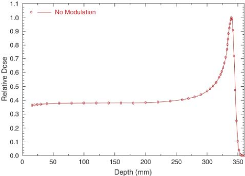 Figure 26.1. Central axis depth dose distribution for an unmodulated 250-MeV proton beam, showing a narrow Bragg peak. (Data from synchrotron at Loma Linda University, CA. From Miller DW. A review of proton beam radiation therapy. Med Phys. 1995;22:1943–1954.) |
The rate of energy loss due to ionization and excitation caused by a charged particle traveling in a medium is proportional to the square of the particle charge and inversely proportional to the square of its velocity. As the particle loses energy, it slows down and the rate of energy loss per unit path length increases. As the particle velocity approaches zero near the end of its range, the rate of energy loss becomes maximum.
The depth dose distribution follows the rate of energy loss in the medium. For a monoenergetic proton beam, there is a slow increase in dose with depth initially, followed by a sharp increase near the end of range. This sharp increase or peak in dose deposition at the end of particle range is called the Bragg peak (Fig. 26.1).
As seen in Figure 26.1, the Bragg peak of a monoenergetic proton beam is too narrow to cover the extent of most target volumes. In order to provide wider depth coverage, the Bragg peak can be spread out by superposition of several beams of different energies (Fig. 26.2). These beams are called the spread-out Bragg peak (SOBP) beams. The SOBP beams are generated by employing a monoenergetic beam of sufficiently high energy and range to cover the distal end of the target volume and adding to it beams of decreasing energy and intensity to cover the proximal portion.
It should be noted in Figures 26.1 and 26.2 that just after the Bragg peak or SOBP, the depth dose curve drops off sharply to zero dose value, although with a slight decrease in slope. This slight decrease in slope is caused by energy-loss straggling of the particles near the end of their range (1).
26.2. Radiobiology
Relative biologic effectiveness (RBE) of any radiation is the ratio of the dose of 250-kVp x-rays to produce a specified biologic effect to the dose of the given radiation to produce the same effect. The specified biologic effect may consist of cell killing, tissue damage, mutations, or any other biologic endpoint. The reference radiation for RBE comparison is sometimes chosen to be cobalt-60 γ rays or megavoltage x-rays for which the RBE has been determined to be about 0.85 ± 0.05 (relative to 250-kVp x-rays).
Although the RBE depends on the type and quality of radiation, dose fractionation, and the biologic endpoint, the factor of critical importance related to RBE is the LET. The greater the LET, the greater is the RBE. Because charged particles, in general, have greater LET than the megavoltage
x-rays, the RBE of charged particles is greater than or equal to 1.0. Neutrons also have RBE greater than 1.0, because of the higher LET caused by their interactions involving recoil protons. Figure 26.3 shows typical cell survival curves for high LET charged particles or neutrons and x-rays. It is seen that the slope of the survival curve is greater for the higher LET radiations, thus giving rise to higher RBE.
x-rays, the RBE of charged particles is greater than or equal to 1.0. Neutrons also have RBE greater than 1.0, because of the higher LET caused by their interactions involving recoil protons. Figure 26.3 shows typical cell survival curves for high LET charged particles or neutrons and x-rays. It is seen that the slope of the survival curve is greater for the higher LET radiations, thus giving rise to higher RBE.
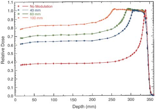 Figure 26.2. Central axis depth dose distribution for a combination of unmodulated 250-MeV and 4-, 6-, and 10-cm range-modulated proton beams. (Data from synchrotron at Loma Linda University, CA. From Miller DW. A review of proton beam radiation therapy. Med Phys. 1995;22:1943–1954.) |
Because the LET of charged particles increases as the particles slow down near the end of their range, so does their RBE. Thus, the RBE of charged particles is greatest in the region of their Bragg peak.
Extensive radiobiologic studies have been carried out to determine the RBE of protons for various irradiation conditions and biologic endpoints. For a review of these studies, the reader is referred to Gerweck and Paganetti (2). Although the LET, and therefore the RBE, of a clinical proton beam continuously increases with depth (as its energy decreases), a single rounded-off value of RBE has been adopted. Most treatment facilities use an RBE of 1.1 for protons relative to cobalt-60 or megavoltage x-ray beams in their dose prescriptions for all proton energies, dose levels, tissues, and regions covered by SOBP. This universal RBE factor of 1.1 has been adopted for practical reasons—to bring clinical response to proton and photon beams into rough agreement.
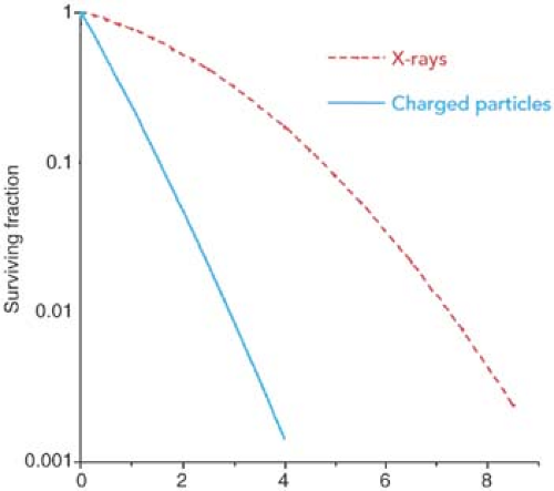 Figure 26.3. Comparison of typical cell survival curves for low linear energy transfer (LET) x-rays and high LET radiation such as heavy charged particles and neutrons. (From Gerweck L, Paganetti H. Radiobiology of charged particles. In: Delaney TF, Kooy HM, eds. Proton and Charged Particle Radiotherapy. Philadelphia: Lippincott Williams & Wilkins; 2008: 8–18.) |
26.3. Proton Accelerators
Protons can be accelerated to high energies by using (a) a linear accelerator, (b) a cyclotron, or (c) a synchrotron. However, the suitability of any type of these accelerators for medical use is dictated by clinical requirements such as high enough beam intensity to deliver a treatment in a short time (e.g., 2–3 minutes) and high enough energy to deliver SOBP beams for any depth tumor (e.g., 160–250 MeV).
Conventional linear accelerators are not suitable for accelerating protons or heavier charged particles to high energies required for radiotherapy. The electric field strength in the accelerator structure is not sufficient to build a compact machine for proton beam therapy. A linear accelerator would require a large amount of space to generate proton beams in the clinically useful range of energies. Therefore, cyclotrons and synchrotrons are currently the main accelerators for proton beam therapy, although new technologies involving high-gradient electrostatic accelerators and laser-plasma particle accelerators are on the horizon.
Cyclotrons and synchrotrons are suitable for use in clinical facilities because they produce proton beams of sufficiently high energy and intensity for radiotherapy. However, they differ in several aspects of beam specification and space requirements. For example, cyclotrons produce high-intensity beams but have limited energy variability and are quite heavy (∼150–200 tons). Synchrotrons are relatively low in weight and produce proton beams of variable energy. Also, the beam current in synchrotrons is lower than in the cyclotrons.
A. Cyclotron
As discussed in Chapter 4, a cyclotron may be visualized as a short metallic cylinder divided into two sections, usually referred to as dees (for their resemblance to the letter D). The dees are highly evacuated and subjected to a constant strength magnetic field applied perpendicular to the plane of the dees. A square wave of electric field is applied across the gap between the two dees. Protons are injected at the center of the cyclotron and accelerated each time they cross the gap. The polarity of the electric field is switched at the exact time the beam re-enters the gap from the opposite direction. The constant magnetic field confines the beam in ever-increasing orbits within the dees until the maximum energy is achieved and extracted. The schematic of cyclotron operation is shown in Figure 4.12. A commercial unit offered by Varian Medical Systems for proton therapy is shown in Figure 26.4.
A cyclotron used in radiotherapy is a fixed-energy machine, designed to generate proton beams of a maximum energy of about 250 MeV (range ∼38 cm in water). This energy would be sufficient to treat tumors at any depth by modulating the range and intensity of the beam with energy degraders. The energy degraders consist of plastic materials of variable thickness and widths to appropriately reduce the range of protons as well as achieve differential weighting of the shifted Bragg peaks in order to create SOBP beams suitable for treating tumors at any depth. For example, in the IBA cyclotron (manufactured by IBA Ltd., Louvain la Neuve, Belgium), the energy degrader consists of a variable-thickness polycarbonate wheel located in the beam line. It is rotated into position to insert appropriate degrader thickness in the beam to reduce the proton range down to the desired depth.
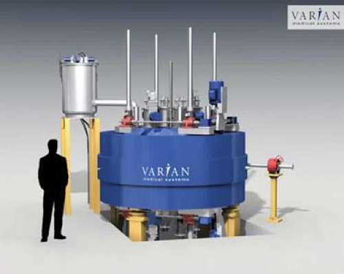 Figure 26.4. Proton therapy cyclotron offered by Varian. (Image courtesy of Varian Medical Systems, Inc., Palo Alto, CA.) |
The cyclotron is isochronous: All the particles in the accelerator revolve at the same frequency regardless of their energy or orbit radius. That means that the accelerator runs continuously during treatment and can deliver high dose rates as needed.
B. Synchrotron
In the synchrotron, a proton beam of 3 to 7 MeV, typically from a linear accelerator, is injected and circulated in a narrow vacuum tube ring by the action of magnets located along the circular path of the beam (Fig. 26.5A). The proton beam is accelerated repeatedly through the radiofrequency (RF) cavity (or cavities), powered by a sinusoidal voltage with a frequency that matches the frequency of the circulating protons. Protons are kept within the tube ring by the bending action of the magnets. The strength of the magnetic field and the RF frequency are increased in synchrony with the increase in beam energy, hence the name synchrotron. When the beam reaches the desired energy, it is extracted. A commercial unit, manufactured by Hitachi Corporation, is shown in Figure 26.5B.
Synchrotrons have a distinct advantage over cyclotrons in that they accelerate the charged particles to precise energies needed for therapy. In other words, the synchrotron is operated to produce the SOBP beams at any desired depth without the use of energy degraders. The cyclotron, on the other hand, operates at a fixed maximum energy and requires energy degraders to treat more
superficial tumors and to create SOBP beams at any depth. Energy degraders are problematic in several respects: They produce greater neutron contamination, require more shielding around the beam-generating equipment, and show higher posttreatment radioactivity from the metal collimators in the energy-degrading system.
superficial tumors and to create SOBP beams at any depth. Energy degraders are problematic in several respects: They produce greater neutron contamination, require more shielding around the beam-generating equipment, and show higher posttreatment radioactivity from the metal collimators in the energy-degrading system.
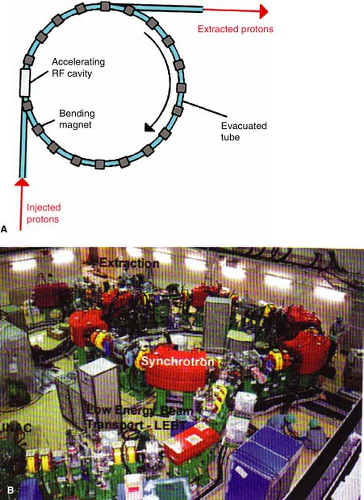 Figure 26.5. A: Schematic diagram illustrating the principle of proton acceleration in a synchrotron. Protons are accelerated in the radiofrequency cavity powered by a sinusoidal voltage. B: Synchrotron manufactured by Hitachi, Ltd., Japan. (From Flanz J. Particle accelerators. In: Delaney TF, Kooy HM, eds. Proton and Charged Particle Radiotherapy. Philadelphia: Lippincott Williams & Wilkins; 2008:27–32.) |
26.4. Beam Delivery Systems
A single accelerator can provide proton beam in several treatment rooms (Fig. 26.6). Beam transport to a particular room is controlled by bending magnets, which can be selectively energized to switch the beam to the desired room. An electronic safety system is provided to ensure that the beam is switched to only one room at a time and only when the designated room is ready to receive the beam. There is very little loss of beam intensity in the transport system—usually less than 5%.
The particle beam diameter is as small as possible during transport. Just before the patient enters the treatment room, the beam is spread out to its required field cross section in the treatment head—the nozzle. This beam spreading is done in two ways: (a) passive scattering, in which the beam is scattered using thin sheets of high-atomic-number materials (e.g., lead, to provide maximum scattering and minimum energy loss); or (b) scanning, in which magnets are used to scan the beam over the volume to be treated. Although most accelerators currently use passive systems, there is a trend toward scanning to spread the beam.
A. Passive Beam Spreading
Using a high-atomic-number scattering foil is the simplest method of spreading a proton beam to a useful field size. The scattered beam follows approximately a Gaussian distribution of intensity, which is then collimated (trimmed) to provide a lateral profile within about 5% uniformity in the central area (excluding the penumbral region). Dual scattering foils are required to obtain large treatment fields of acceptable uniformity—within 5%. The first foil of uniform thickness spreads the beam to a large size and the second foil of differentially varied thickness modulates the beam intensity profile into a uniform distribution.
Passive systems require custom blocking to shape the field. The field outline, obtained from data files generated by the treatment-planning system, are digitized to design field apertures from the custom blocking equipment (e.g., casting Cerrobend blocks into Styrofoam molds or machining shielding material directly). Since field apertures are placed close to the patient surface (to reduce penumbra), they tend to be large and too heavy for manual lifting.
Because the dose falloff beyond the Bragg peak is very sharp, the beam stopping distribution needs to be tailored to the dose in depth to make the isodose surface conform to the distal shape of the target volume. In passive beam spreading systems, range compensators of low-atomic-number
materials (e.g., plastics or wax) are used to compensate simultaneously for external patient surface irregularity, internal tissue heterogeneity, and the shape of the distal planning target volume (PTV) surfaces. In the design of these compensators, allowance is also made for alignment errors, patient and internal organ motion, and uncertainties in the localization of the PTV and organs at risk (3).
materials (e.g., plastics or wax) are used to compensate simultaneously for external patient surface irregularity, internal tissue heterogeneity, and the shape of the distal planning target volume (PTV) surfaces. In the design of these compensators, allowance is also made for alignment errors, patient and internal organ motion, and uncertainties in the localization of the PTV and organs at risk (3).
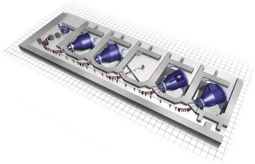 Figure 26.6. Schematic of proton beams from cyclotron transported to various rooms. (Courtesy of Varian Medical Systems, Inc., Palo Alto, CA.) |
Passive beam spreading systems also include range modulators to spread the Bragg peak in depth over the PTV thickness in the direction of the beam. The range modulator is a propeller-shaped wheel that rotates to insert successively thicker layers of plastic into the beam, thereby providing a differential pullback of the Bragg peak. By controlling the thickness of each layer and the duration of its insertion in the beam, an SOBP is obtained to cover the PTV.
B. Pencil Beam Scanning
One problem with passive beam spreading is the interdependence of range and field size. In order to obtain uniform fields of acceptable uniformity, the scattering foil thickness has to be increased, which in turn results in the degradation of beam energy or the loss of treatment range. The problem can be eliminated by pencil beam scanning. For example, uniform fields can be produced without loss of range by magnetically scanning a narrow beam of protons. The Paul Scherrer Institute in Switzerland was the first to implement beam scanning with protons. In this system, the tissue region of interest is divided into a three-dimensional grid of volume elements (voxels). The scanning system delivers specific doses at the grid points by placing the Bragg peaks within the voxels. Fields of any size and shape can be generated by pencil beam scanning, thus obviating the need for a custom-designed field aperture for every treatment portal. Because pencil beams of any energy and intensity are available, range compensators are also not required. Thus, the pencil beam scanning system allows computer-controlled delivery of dose as a function of beam intensity, field size, depth, beam position, and direction. An optimization process is used to calculate weights of thousands of individual pencil beams to generate a single treatment port. Optimally weighted Bragg peaks are thus distributed three-dimensionally to deliver a uniform dose to the target volume.
Beam scanning with protons is ideally suited for intensity-modulated proton therapy (IMPT). As in the case of photon intensity-modulated radiation therapy (IMRT), multiple ports are used in IMPT. Each port is designed with inhomogeneous proton fluence distribution so that when all the fields are combined, a homogeneous dose is delivered to the target volume. Clinical implementation of fully automated IMPT at the Paul Scherrer Institute is discussed by Lomax et al. (4). A three-field IMPT plan used in the treatment of a patient with a head and neck tumor is shown in Figure 26.7 as an example.
Pencil beam scanning is a precise and efficient mode of proton beam delivery for both the conventional and IMPT techniques. The major advantage is that no field-specific hardware
(scattering foils, field apertures, and physical range compensators) is required and sequential fields are automatically delivered without entering the treatment room. The disadvantage is that pencil beam scanning for both the conventional and IMPT techniques has a higher sensitivity to organ motion than the passive methods of beam scattering. In other words, intensity modulation is temporally not synchronized with organ motion during beam delivery. It should also be mentioned that the photon IMRT suffers from the same problem.
(scattering foils, field apertures, and physical range compensators) is required and sequential fields are automatically delivered without entering the treatment room. The disadvantage is that pencil beam scanning for both the conventional and IMPT techniques has a higher sensitivity to organ motion than the passive methods of beam scattering. In other words, intensity modulation is temporally not synchronized with organ motion during beam delivery. It should also be mentioned that the photon IMRT suffers from the same problem.
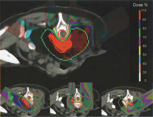 Figure 26.7. An example of an intensity-modulated proton therapy (IMPT) treatment plan for a tumor in the head and neck region. Three fields with nonhomogeneous fluences are delivered to obtain a conformal dose distribution for the planning target volume located between two critical structures, the esophagus and the spinal cord. (From Pedroni E. Pencil beam scanning. In: Delaney TF, Kooy HM, eds. Proton and Charged Particle Radiotherapy. Philadelphia: Lippincott Williams & Wilkins; 2008:40–49.) |
Limitations of pencil beam scanning have been discussed by several investigators (5,6,7). Some of the strategies to counteract the organ motion problem include (a) “repainting” the dose multiple times over the organ motion period in order to achieve a statistical averaging effect on the dose distribution; (b) increasing the scanning speed and thereby increasing the number of repaintings over the target volume, which further reduces the motion error through a greater degree of randomization and better averaging statistics; (c) synchronizing beam delivery with the patient’s breathing cycle; and (d) tumor tracking during treatment. The problem of intrafraction organ motion is common to both photon and proton IMRT. It needs further investigation before appropriate solutions are found for either modality.
Related posts:

Stay updated, free articles. Join our Telegram channel

Full access? Get Clinical Tree


